Article

Optical Trapping of Chiral Particles by Dual Laser Beams

1
School of Electronic Engineering, Xi’an University of Posts & Telecommunications, Xi’an 710121, China
2
The 39th Research Institute of China Electronics Technology Corporation, Xi’an 710065, China
3
School of Physics and Optoelectronic Engineering, Xidian University, Xi’an 710071, China
*
Author to whom correspondence should be addressed.
Photonics 2023, 10(8), 905; https://doi.org/10.3390/photonics10080905
Submission received: 4 July 2023 / Revised: 30 July 2023 / Accepted: 31 July 2023 / Published: 4 August 2023

Abstract

:
In this paper, an analytical method for studying the radiation force (RF) of chiral spheres generated by dual laser beams is presented under the framework of generalized Lorenz–Mie theory (GLMT). According to the coordinate transformation relations, the arbitrarily incident laser beam is represented by vector spherical harmonic functions (VSHFs) in the sphere system. The entire induced field expression coefficients of dual laser beams can be obtained by superposition of each illuminated field. Based on the momentum conservation theory, the concrete expression of lateral and axial RF on chiral sphere is derived. The current theories are shown to be valid by comparison with the existing reference. To investigate the stable capture state of chiral sphere, the influences of the corresponding parameters of chiral particles and dual laser beams on the trapping and manipulation are investigated in detail. The analytical study on the RF of dual laser beams on chiral particles is an efficient method for improving optical tweezers technology and can become an encouraging approach to realize the high accuracy operation of chiral particles.

1. Introduction

Optical tweezers technology was first discovered by Ashkin according to the experimental phenomenon of capturing and accelerating particles by laser beam [1,2], which has attracted widespread attention in the fields of molecular biology [3,4,5,6,7,8,9], physics [10], nanotechnology [11], particle sizing, and chemical engineering since it can capture and manipulate living samples without physical contact with particles. At present, optical tweezers technology has become an important means for manipulating various particles due to its special characteristics [12]. In recent years, scholars have studied dielectric meta-surfaces that allow the parallel trapping of multiple particles [13], and they experimentally demonstrated the near-field enhancement provided by the meta-surface and simulated its trapping performance. Generally, in the current literature on the correlations of the particles and the shaped beam, optical tweezers are mainly set using a single laser beam [14,15,16,17]. With the continuous progress of laser technology, the research on the interaction between particles and single beams is relatively mature. Various new wave sources such as the Laguerre–Gaussian beam [18], Bessel beam [19], Hermite beam [20], and various vortex beams have become the research focus of many scholars [21,22]. However, single beam trapping typically only allows for the capture of particles at a specific location, limiting its applicability in studying multi-particle systems and complex microstructures. Additionally, due to the limited trapping range of a single beam, it may not be effective in capturing particles in complex or sparsely distributed particle systems, leading to reduced experimental efficiency and accuracy. To address these limitations and drawbacks associated with single beam particle trapping, composite dual beam particle trapping has emerged as a promising solution. This technique offers high precision, high resolution, and high efficiency, effectively overcoming the shortcomings of single beam methods. As a result, it has generated significant interest in various fields, including biomedicine, remote sensing, communication, and micro-manipulation [23]. Dual beam optical trap was first proposed by Ashkin [24]. He demonstrated the stability of dual beam optical trap by experimentally tracking particles of micron size in liquid and gas. On this basis, a large number of scholars have studied the capture and manipulation of particles by dual beam optical tweezers. Koen et al. [25] described the design and construction of two different types of multiple beam optical tweezers, and the advantages and disadvantages of optical tweezers are discussed, along with details of specific implementations. In 1998, Zemánek et al. utilized the coupled dipole theory to study the RF of Rayleigh spheres irradiated by a Gaussian standing wave [26] and gave a detailed discussion on the influence of a wide variety of parameters on RF [27,28]. However, the method is only effective to analyze the RF on smaller targets. For larger targets, Gauthier et al. proposed the radial optics method to study the RF on spherical particles immersed in a dual beam trap and demonstrated the mechanism of particle manipulation and trapping [29]. For targets of comparable size with incident wavelength, dipole and geometric optical methods will no longer apply. To solve this problem, Gouesbet et al. [30] proposed the GLMT to research the interactions between light and particles and gave detailed discussions of shape factors [31]. According to the study, Zemánek et al. made a comparison in optical trapping performance of submicron-sized particles in single progressive beam and dual Gaussian standing wave [28], and proved that a standing wave well can provide greater axial capture force than single Gaussian beam under certain conditions. Cizmar et al. [32] proposed a method for three-dimensional compression of high refractive index particles by dual Bessel beam interference, which is used to study the RF of the back-propagating Bessel standing beam. In addition, Casabri et al. simulated the RF of three beams and found that the theoretical results are consistent with the experimental data [33]. Horst et al. [34] calculated the RF on isotropic sphere irradiated by two back-propagating Gaussian beams. Zhao et al. [35] researched the trapping performance of nanoparticles surrounded by absorbing dielectric illuminated by bi-linearly polarized light. Crivellari [36] proposed a new type of dual-well optical tweezers designed for counter-propagating beams by using the conservation of linear momentum. Zhang et al. [37] proved that particles in dual orthogonal polarized plane waves are subject to trapping forces. Later, Li et al. [38] studied the RF of dual counter-propagating Gaussian beam on an anisotropic sphere placed in it based on GLMT theory, and analyzed the effect of incident angles on the RF. Nevertheless, the references mentioned above mainly reflected on the research of RF on homogeneous isotropic particles by dual beams. There are still few theoretical studies of the trapping force of dual laser beam on chiral particles.
Chiral medium was first proposed as an optically active substance in the 19th century. Chiral structures refer to geometric configurations that cannot be overlapped with their mirror images through translation and rotation. Typical examples of such structures include helices (both left-handed and right-handed), mirror-image enantiomers of molecules, DNA, amino acids, and more. With its unique optical rotation characteristics, chiral material has been widely manufactured and used in biomedicine, micro-molecular manipulation, physics, and fuel combustion [39,40,41]. In the past few decades, the interaction between chiral material and laser beams has been extensively studied by many researchers. In addition to numerical methods based on T-matrix [42], moment method [43,44], FDTD [45], and FDFD [46], the analytical method relies on the advantages of an accurate solution; many scholars have been able to investigate the scattered properties of chiral particles. Gordon firstly tried to obtain the derivation of the scattered amplitude matrix of chiral particles by using the GLMT [47]. Later, Wu [48] proposed an analytical method to analyze the scattering of large chiral particles and deduced the scattering coefficients. During recent years, Cui researched the analytical solutions of Laguerre–Gaussian beam on chiral particles with arbitrary shapes [49]. Our team [50] analytically studied the interactions between high-order Bessel beam and cluster chiral nanostructures. In order to better investigate the electromagnetic interactions with chiral media, many scholars have devoted themselves to the study of capture performance of chiral particles. In 2011, Guzatov et al. [51] reported the RF of circularly polarized plane waves on chiral spheres. In 2014, Chen et al. [52] analyzed the lateral trapping effects of Bessel beams on chiral particles by using the dipole approximation method. In 2017, based on Fast Fourier Transform (FFT), Du and other scholars [53] proposed a pure numerical method to calculate the trapping force of chiral materials. However, FFT algorithms usually need to calculate the optical force in the whole space, which leads to a serious decline in the calculation speed. In order to solve the problem, Zheng et al. deduced the analytical expression of surface light force based on the GLMT and eliminated the limitation of calculation speed [54,55,56]. Shang et al. reported an iterative analytical solution for the RF of chiral dielectric spheres in large sizes [57]. However, the above-mentioned work mainly involves the effects of single planar waves and progressive circular Gaussian beams on the trapping properties of chiral particles. The literature has rarely mentioned studies on the capture performance of standing laser beam on chiral spheres. Investigating RF on spherical particles by Gaussian standing beams is very different from the traditional single beam, especially for chiral nanoparticles, which need to be further researched. In the formula derivation presented in this paper, we stably and efficiently calculate the scattering coefficients of chiral spheres using the iterative formula and the recursive relationship for the logarithmic derivatives of the Riccati–Bessel functions [18]. We then apply this method to the calculation of the radiation force and rigorously derive the expression for the trapping force on chiral spheres under the illumination of dual laser beams. Furthermore, our derivation is based on a more general scenario where the scattering coefficients and radiation force formulas are applicable to the study of trapping forces induced by dual beams of arbitrary shapes if the expansion coefficient of the incident beam is known. The results on RF of chiral nanoparticles with arbitrary polarized standing laser beams may have potential application value in microscopy detection and manipulation of chiral structures.
The thesis is arranged as follows: In the second part, based on GLMT, the incident field and scattered field of chiral nanoparticles by arbitrarily irradiated double laser beams are deduced. Applying the deduced scattered result, the third part combines the momentum conservation theory to obtain the lateral and axial RF on chiral spheres by double laser beams. In the fourth part, software simulations are used to present the numerical influence of various parameters. Finally, Section 5 is the summary of the thesis. We hope that the theoretical results of this paper can make contributions to the study of optical capture of chiral particles. In the subsequent analysis, a time dependence of the form exp ( i ω t ) is assumed for all the electromagnetic (EM) fields but is ignored throughout the treatment, where ω is the angular frequency.

2. Theoretical Analysis

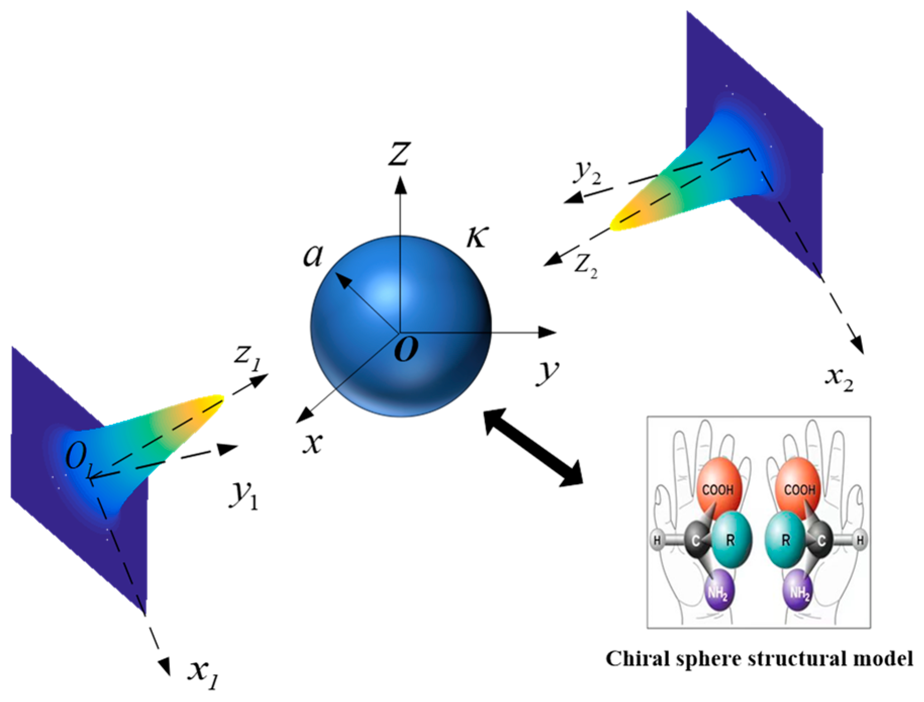
In this paper, the expansion of dual laser beams in a spherical system is obtained first, and then the scattered theory of chiral sphere by single beam is extended to dual laser beams. As shown in Figure 1, the subject researched here is the random irradiation of dual Gaussian beams with arbitrary polarizations on chiral particle system. To facilitate a better understanding of the chirality properties, we have provided molecular structures inside the chiral sphere that exhibit mirror-image enantiomeric characteristics in Figure 1. Suppose the radius of the chiral particle is a , the sphere is located at O x y z system, and its center is coincident with center O . The first laser beam transmits along + z 1 direction in system O 1 x 1 y 1 z 1 , and its beam center is O 1 . The second laser beam propagates along positive z 2 direction in system O 2 x 2 y 2 z 2 and its beam center coordinate is O 2 . The beam centers O 1 and O 2 in the particle coordinate system O x y z are denoted as ( x 1 , y 1 , z 1 ) and ( x 2 , y 2 , z 2 ) 
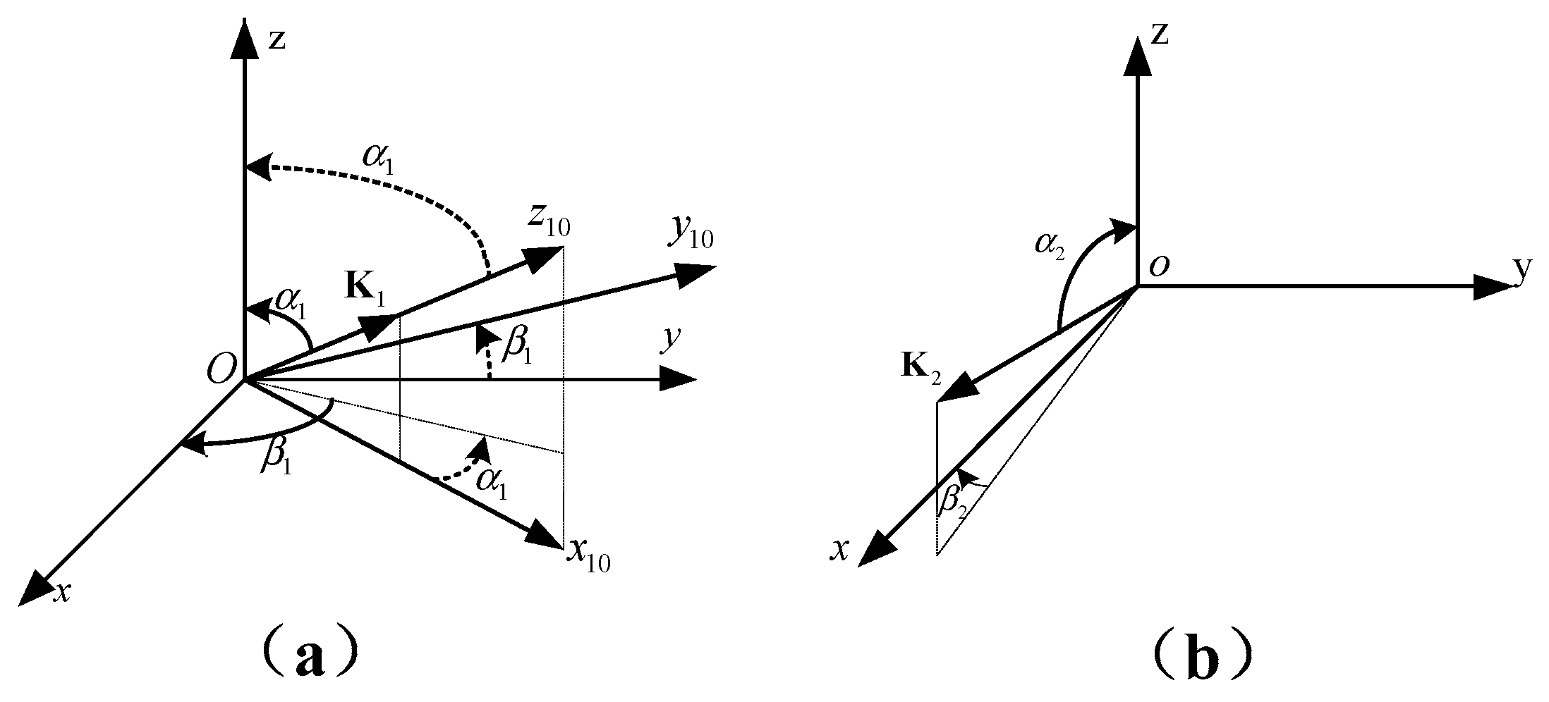
. Take the first laser beam as example, we establish an intermediate system O x 10 y 10 z 10 similar to the first laser beam system O x 1 y 1 z 1 as presented in Figure 2a, the angles α 1 and β 1 indicate the arbitrariness of the propagation and polarization about the first laser beam, where α 1 is set as the angle between first beam transmitted axis and z-axis and β 1 refers to the angle between the first beam polarized orientation and x-axis. Similarly, α 2 and β 2 are set to be the angle of incidence and polarization of secondary laser beam. As presented in Figure 2b, K 1 , K 2 represent the wave numbers of dual Gaussian waves. Since the case is the same with Figure 2a, only the representation of the angle is different, so the illustration is not repeated here.
As presented in Figure 2, the first laser beam can be expanded according to the VSHFs in the intermediate system O x 10 y 10 z 10 as follows:
E i 1 = E 0 n = 1 m = n n a m n i 10 M m n ( 1 ) r 10 , k 0 + b m n i 10 N m n ( 1 ) r 10 , k 0 H i 1 = E 0 k 0 i ω μ 0 n = 1 m = n n a m n i 10 N m n ( 1 ) r 10 , k 0 + b m n i 10 M m n ( 1 ) r 10 , k 0
In the above equations, k 0 = 2 π / λ , where λ presents the wavelength of the laser beam in free space. E 0 represents electric field amplitude. ω represents the angular frequency, μ 0 is the surrounding medium’s magnetic permeability. Superscript “10” in the above equation denotes the variates in the intermediate system O x 10 y 10 z 10 . The r 10 means the position vector of the center O 1 of the first beam in the intermediate system O x 10 y 10 z 10 . The expansion coefficients a m n i 10 , b m n i 10 can be obtained as follows:
a m n i 10 = i g n , T E m C n m , b m n i 10 = g n , T M m C n m
where the beam factor g n , T E m and g n , T M m can be obtained by using the traditional integral method and the specific expansion can refer to the literature [58,59].
C n m = i n 1 2 n + 1 n ( n + 1 ) , m 0 ( 1 ) | m | ( n + | m | ) ! ( n | m | ) ! i n 1 2 n + 1 n ( n + 1 ) , m < 0
In Equation (1), M m n ( q ) and N m n ( q ) denote the vector spherical harmonic functions (VSHFs) and q = 1 , 2 , 3 , 4 represents four kinds of spherical Bessel functions in the SVWFs, Whose expressions used here are the same as those used in Ref. [60]:
M m n ( q ) = i m z n ( q ) ( k r ) P n m ( cos θ ) sin θ e i m ϕ θ ^ z n ( q ) ( k r ) d P n m ( cos θ ) d θ e i m ϕ ϕ ^ N m n ( q ) = n ( n + 1 ) z n ( q ) ( k r ) k r P n m ( cos θ ) e i m ϕ r ^ + 1 k r d r z n ( q ) ( k r ) d r d P n m ( cos θ ) d θ e i m ϕ θ ^     + i m 1 k r d r z n ( q ) ( k r ) d r P n m ( cos θ ) sin θ e i m ϕ ϕ ^
where z n ( q ) k r represents an appropriate kind of spherical Bessel functions: the first kind j n , the second kind y n , or the third kind h n ( 1 ) and h n ( 2 ) , denoted by q = 1 , 2 , 3 , or 4 , respectively. P n m ( cos θ ) is the associated Legendre Function of the first kind. Then, the incident, scattered, and internal fields can be expressed as an infinite series of these vector functions.
According to the coordinate transformation theorem [61], the VSHFs of the intermediate and particle coordinate systems are related as follows:
( M , N ) m n ( 1 ) r 10 , k 0 = s = n n ρ ( m , s , n ) ( M , N ) s n ( 1 ) r 1 , k 0
By using the rotation relations between coordinates [62], the coordinate of O 1 in the middle system O x 10 y 10 z 10 can be obtained as ( x 10 , y 10 , z 10 ) :
x 10 y 10 z 10 = cos α 1 cos β 1 sin α 1 cos β 1 sin β 1 sin α 1 cos α 1 0 cos α 1 sin β 1 sin α 1 sin β 1 cos β 1 x 1 y 1 z 1
By substituting Equation (5) into Equation (1), the final incident field expansion of the first laser beam in the sphere system O x y z can be expressed as:
E i p 1 = E 1 n = 1 m = n n a m n i p 1 M m n ( 1 ) r 1 , k 0 + b m n i p 1 N m n ( 1 ) r 1 , k 0 H i p 1 = E 1 k 0 i ω μ 0 n = 1 m = n n a m n i p 1 N m n ( 1 ) r 1 , k 0 + b m n i p 1 M m n ( 1 ) r 1 , k 0
where
a m n i p 1 , b m n i p 1 = s = n n ρ ( s , m , n ) C n s a m s i 10 , b m s i 10
ρ s , m , n = ( 1 ) m + s n + m ! n m ! n + s ! n s ! 1 / 2 u m s ( n ) α
u m s ( n ) α = σ n + s n m σ n s σ   cos α 2 2 σ + m + s sin α 2 2 n 2 σ m s
where the superscript “1” represents the corresponding parameters of the first laser beam. r 1 denotes the position vector of the center O 1 of the first laser beam in the sphere system O x y z . a m n i p 1 and b m n i p 1 represent the first incident coefficients. Superscript i p 1 represents the x-direction line polarization, y-direction line polarization, right circularly polarization (RCP), and left circularly polarization (LCP) wave incidence when i p 1 is i x 1 ,   i y 1 ,   i R 1 ,   i L 1 , respectively. The incident coefficients of different polarizations are satisfied:
a m n i y 1 = i b m n i x 1 b m n i y 1 = i a m n i x 1 a m n i R 1 = 2 ( a m n i x 1 + b m n i x 1 ) / 2 b m n i R 1 = 2 ( b m n i x 1 + a m n i x 1 ) / 2   a m n i L 1 = 2 ( a m n i x 1 b m n i x 1 ) / 2 b m n i L 1 = 2 ( b m n i x 1 a m n i x 1 ) / 2
Similar to the first beam, the expression of the second incident laser beam in the sphere system O x y z is:
E i p 2 = E 2 n = 1 m = n n a m n i p 2 M m n ( 1 ) r 2 , k 0 + b m n i p 2 N m n ( 1 ) r 2 , k 0 H i p 2 = E 2 k 0 i ω μ 0 n = 1 m = n n a m n i p 2 N m n ( 1 ) r 2 , k 0 + b m n i p 2 M m n ( 1 ) r 2 , k 0
where
a m n i p 2 , b m n i p 2 = s = n n ρ ( s , m , n ) C n s a m s i 20 , b m s i 20
At this time, the total incident fields of the dual laser beams can be gained by adding electromagnetic fields of each incident Gaussian beams:
E i p = E i p 1 + E i p 2 H i p = H i p 2 + H i p 2
the total expansion coefficients can be expressed as:
a m n i p = a m n i p 1 + a m n i p 2 , b m n i p = b m n i p 1 + b m n i p 2
For the chiral medium sphere, the intrinsic structure relationship is as follows:
D = ε c E + i κ ε 0 μ 0 H B = i κ ε 0 μ 0 E + μ c H
In the above formula, ε c ,   μ c , and κ represent the dielectric constant, magnetic permeability, and chiral parameters. ε 0 and μ 0 represent the dielectric constant and magnetic permeability in free space. Considering that laser beam propagation in the optically active medium can be always broken down into two patterns: RCP and LCP beams, there are two kinds of wave numbers in the chiral medium: RCP beam with k R and LCP beam with k L , which can be denoted as [63]:
k R = ω ε c μ c + κ ε 0 μ 0 k L = ω ε c μ c κ ε 0 μ 0
According to the previous work [63,64], the internal fields of chiral spheres can be obtained by SVWFs as [48]:
E int = n = 1 m = n n A m n M m n ( 1 ) ( r , k R ) + A m n N m n ( 1 ) ( r , k R ) + B m n M m n ( 1 ) ( r , k L ) B m n N m n ( 1 ) ( r , k L ) H int = Q n = 1 m = n n A m n N m n ( 1 ) ( r , k R ) + A m n M m n ( 1 ) ( r , k R ) + B m n N m n ( 1 ) ( r , k L ) B m n M m n ( 1 ) ( r , k L )
where   Q = i μ c ε c , A m n   , and B m n denote the internal coefficients. Similarly, the scattering fields are expressed in the following forms:
E s = E 0 n = 1 m = n n [ A m n s M m n ( 3 ) ( r , k 0 ) + B m n s N m n ( 3 ) ( r , k 0 ) ] H s = k 0 E 0 i ω μ 0 n = 1 m = n n [ A m n s N m n ( 3 ) ( r , k 0 ) + B m n s M m n ( 3 ) ( r , k 0 ) ]
Based on the boundary conditions in [48] and by substituting Equations (14), (18) and (19), the scattered coefficients A m n s and B m n s of dual laser beams on chiral sphere can be obtained as follows:
A m n s = A n s a a m n i p + A n s b b m n i p   B m n s = B n s a a m n i p + B n s b b m n i p ,
where
A n s a = ψ n ( x 0 ) ξ n ( x 0 ) D n ( 1 ) ( x R ) η r D n ( 1 ) ( x 0 ) η r D n ( 1 ) ( x R ) D n ( 3 ) ( x 0 ) + D n ( 1 ) ( x L ) η r D n ( 1 ) ( x 0 ) η r D n ( 1 ) ( x L ) D n ( 3 ) ( x 0 ) η r D n ( 3 ) ( x 0 ) D n ( 1 ) ( x R ) η r D n ( 1 ) ( x R ) D n ( 3 ) ( x 0 ) + η r D n ( 3 ) ( x 0 ) D n ( 1 ) ( x L ) η r D n ( 1 ) ( x L ) D n ( 3 ) ( x 0 ) ,
A n s b = ψ n ( x 0 ) ξ n ( x 0 ) η r D n ( 1 ) ( x R ) D n ( 1 ) ( x 0 ) η r D n ( 1 ) ( x R ) D n ( 3 ) ( x 0 ) η r D n ( 1 ) ( x L ) D n ( 1 ) ( x 0 ) η r D n ( 1 ) ( x L ) D n ( 3 ) ( x 0 ) η r D n ( 3 ) ( x 0 ) D n ( 1 ) ( x R ) η r D n ( 1 ) ( x R ) D n ( 3 ) ( x 0 ) + η r D n ( 3 ) ( x 0 ) D n ( 1 ) ( x L ) η r D n ( 1 ) ( x L ) D n ( 3 ) ( x 0 ) ,
B n s a = A n s b ,
B n s b = ψ n ( x 0 ) ξ n ( x 0 ) η r D n ( 1 ) ( x R ) D n ( 1 ) ( x 0 ) D n ( 1 ) ( x R ) η r D n ( 3 ) ( x 0 ) + η r D n ( 1 ) ( x L ) D n ( 1 ) ( x 0 ) D n ( 1 ) ( x L ) η r D n ( 3 ) ( x 0 ) D n ( 3 ) ( x 0 ) η r D n ( 1 ) ( x R ) D n ( 1 ) ( x R ) η r D n ( 3 ) ( x 0 ) + D n ( 3 ) ( x 0 ) η r D n ( 1 ) ( x L ) D n ( 1 ) ( x L ) η r D n ( 3 ) ( x 0 ) ,
In the above equations, ψ n ( z ) = z j n ( z ) and ξ n ( z ) = z h n ( 1 ) ( z ) are the first and the third type of Riccati–Bessel functions, respectively. D n ( 1 ) ( z ) = ψ n ( z ) / ψ n ( z ) and   D n ( 3 ) ( z ) = ξ n ( z ) / ξ n ( z )   denote logarithmic derivatives of the Riccati–Bessel functions. The recursive relationship among D n ( 1 ) ( z ) , D n ( 3 ) ( z ) and ψ n ( z ) / ξ n ( z ) can be referred in [48]. In Equations (21)–(24), η r = ε / μ / ε c / μ c , x 0 = k a , x R = k R a , x L = k L a represent the dimensional parameters of the chiral dielectric sphere, respectively.

3. Calculation of Radiation Force

Several decades ago, many scholars studied the RF on a sphere irradiated by a light beam. In accordance with the typical EM theory, the optical beam will carry momentum and energy in the process of transmission. While the strong convergent laser beam irradiates on the particles, because of the existence of scattering phenomenon, some momentum is delivered from incident beam to irradiated particles. Under the momentum mechanics, the RF acting on particles is equivalent to the change rate of the momentum received from incident light. Based on electromagnetic scattering theory and Maxwell’s tensor theory, we derived an expression for the RF on chiral sphere particle by dual Gaussian beams:
F = s n ^ · T d S
T = 1 2 Re ε E E * + μ H H * 1 2 ε E 2 I 1 2 μ H 2 I
where T is the Maxwell stress tensor, d S represents an arbitrary closed spherical surface surrounding the chiral sphere, n ^ represents the outward normal unit vector, I means the dual tensor, and     represents mean value of time. E = E i p + E s and H = H i p + H s represent the total fields.
By substituting Equation (26) into Equation (25) and using recursive and orthogonal relations of the SWVFs [65], the trapping force of the chiral sphere under the illumination of dual Gaussian beams can be obtained as:
F x + i F y = n P 0 π c k 0 2 w 2 n = 1 m = n n [ N m n 1 N m + 1 n 1 ( n m ) ( n + m + 1 ) ( a m n i p B m + 1 n s *   + b m n i p A m + 1 n s * + B m n s a m + 1 n i p * + A m n s b m + 1 n i p * + 2 A m n s B m + 1 n s * + 2 B m n s A m + 1 n s * )   i N m n 1 N m + 1 n 1 1 ( n 1 ) ( n + 1 ) ( n m 1 ) ( n m ) ( 2 n 1 ) ( 2 n + 1 ) ( a m n i p A m + 1 n 1 s * + b m n i p B m + 1 n 1 s * + A m n s a m + 1 n 1 i p * + B m n s b m + 1 n 1 i p * + 2 A m n s A m + 1 n 1 s * + 2 B m n s B m + 1 n 1 s * ) i N m n 1 N m + 1 n + 1 1 n ( n + 2 ) ( n + m + 1 ) ( n + m + 2 ) ( 2 n + 1 ) ( 2 n + 3 ) ( a m n i p A m + 1 n + 1 s * +         b m n i p B m + 1 n + 1 s * + A m n s a m + 1 n + 1 i p * + B m n s b m + 1 n + 1 i p * + 2 A m n s A m + 1 n + 1 s * + 2 B m n s B m + 1 n + 1 s * ) ]
F z = 2 n P 0 π c k 0 2 w 2 Re n = 1 m = n n [ i n ( n + 2 ) ( n m + 1 ) ( n + m + 1 ) ( 2 n + 1 ) ( 2 n + 3 ) N m n 1 N m n + 1 1 × ( a m n + 1 i p A m n s   * + A m n + 1 s a m n i p * + b m n + 1 i p B m n s * + B m n + 1 s b m n i p * + 2 A m n + 1 s A m n s *   + 2 B m n + 1 s B m n s * ) m N m n 2 ( a m n i p B m n s * + b m n i p A m n s * + 2 A m n s B m n s * ) ]
In the above equations, N m n = ( 2 n + 1 ) ( n m ) ! / 4 π / ( n + m ! ) , m = 0 , ± 1 , ± 2 , , ± n , c denotes the light speed in vacuum. p = π w 2 ε / μ E 0 2 / 4 represents the incident power.

4. Numerical Simulation

In this part, numerical calculations taking into account the influence of variety of parameters, for example beam polarization form, waist width, particle radius, chiral parameters, particle refractive index, and material losses on RF, are analyzed in detail. Considering that there are few reports on optical trapping experiments in air, the main reason is that the high refractive index contrast between air and liquid makes it more difficult to achieve optical capture of a single beam in air than in liquid [
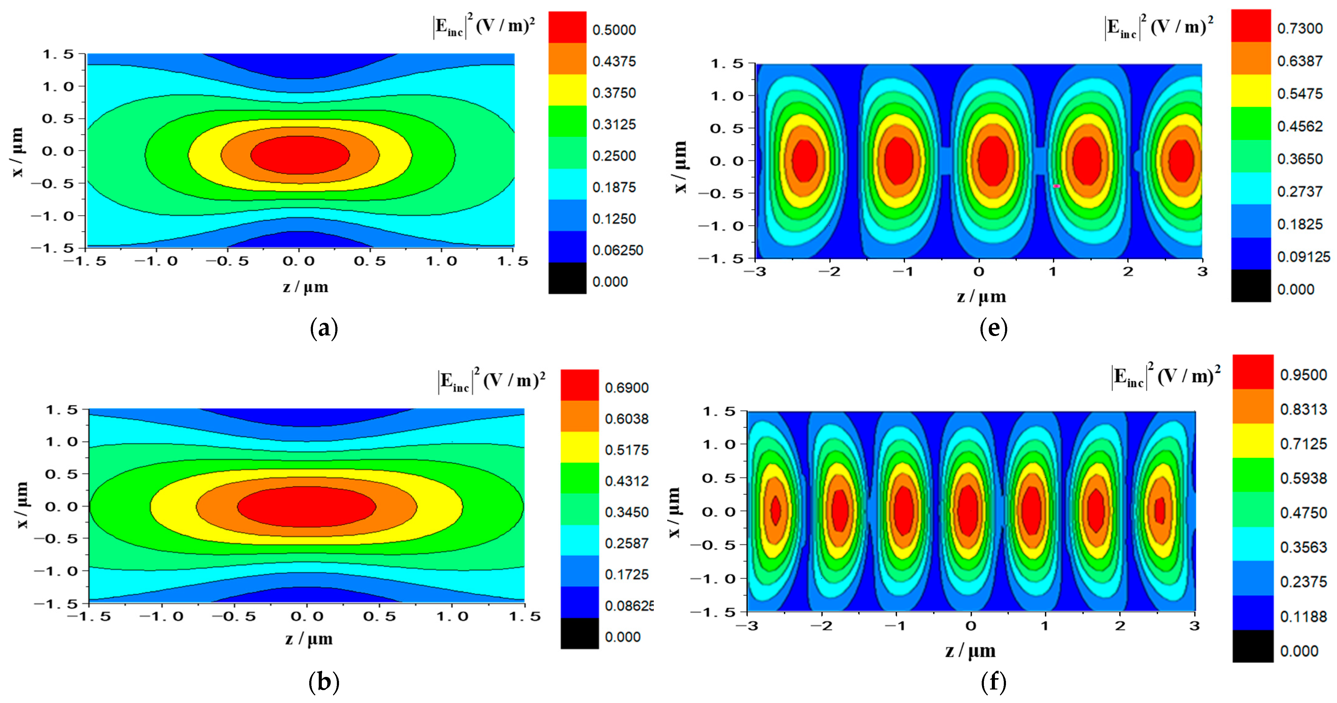
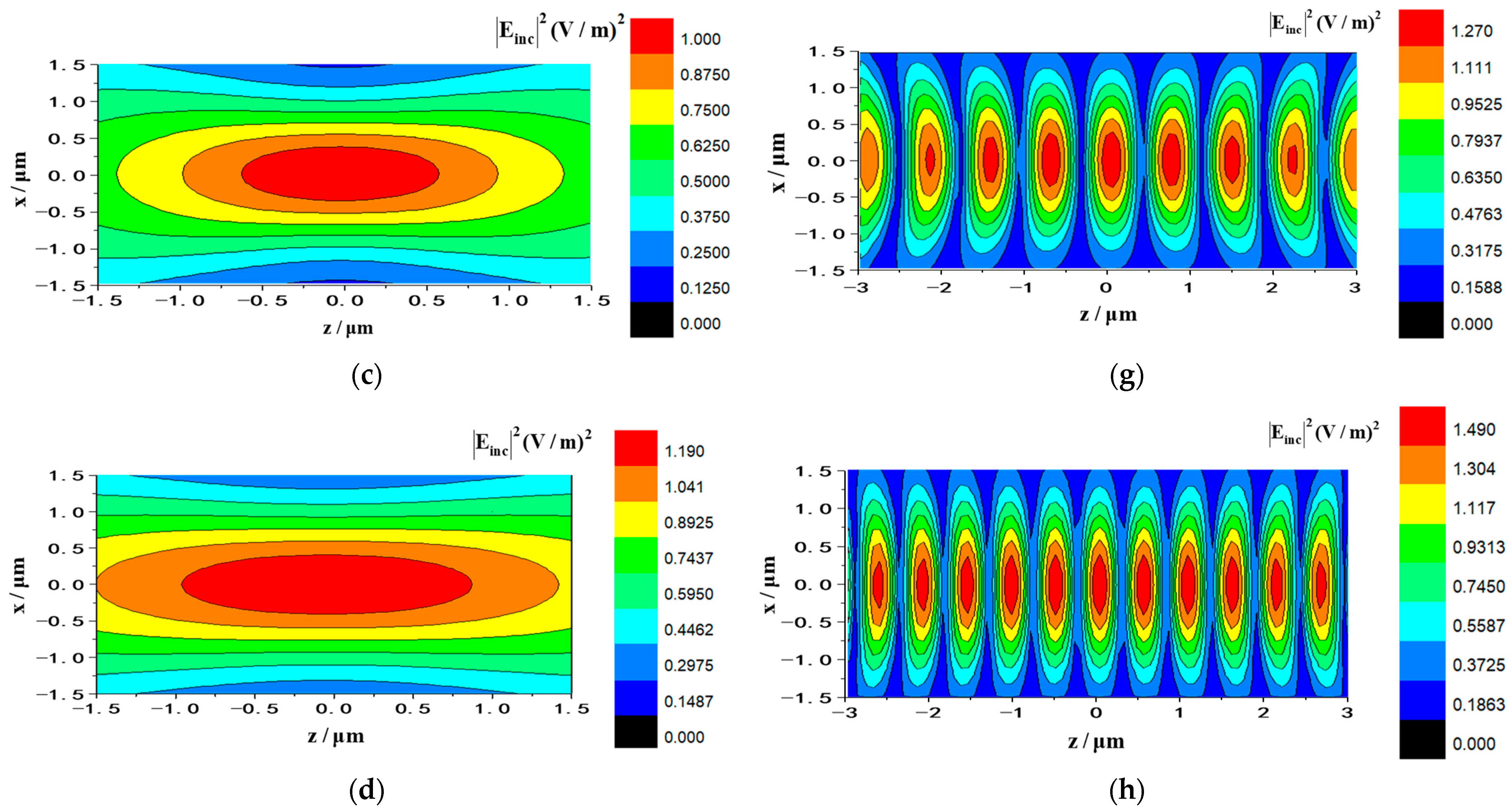
66]. However, the standing beam configuration consisting of dual beams can offer sufficient chance to control airborne particles, as the capture is carried out with the amendments of radiation pressure. In general, creating a standing wave well requires two relativistic propagating laser beams carrying the same amplitude, the same frequency, and a fixed phase difference. In order to leave an intuitive show about standing Gaussian beam, difference between magnitude plots for the electric field of single Gaussian beam and Gaussian standing beam with varying waist width are given in Figure 3, in which, the single Gaussian beam travels in the + z direction and the standing wave consists of two Gaussian beams transmitting along + z direction and z direction, respectively. All beams are denoted by RCP-polarization and wavelength λ = 1064   nm . The electric field amplitude is denoted E 0 = 1 , the direction of standing wave is set α 1 = 0 ° , α 2 = 180 ° , and the beam center is x 1 = y 1 = 0 , x 2 = y 2 = 0 . It can be found that in Figure 3a–d, as the beam waist width increases, the electric field intensity distribution range gradually expands, at this time the convergence degree and the gradient force well will decrease, but the capture position is always at the center of the single beam. However, by contrast with single laser beam, the standing laser beam can form periodic nodes and antinodes as shown in Figure 3e–h, and since a battery of trapping points are constituted following the axis of wave propagation, the standing potential well can capture particles in multiple positions, which is the advantage of the Gaussian standing potential well compared with a single beam.
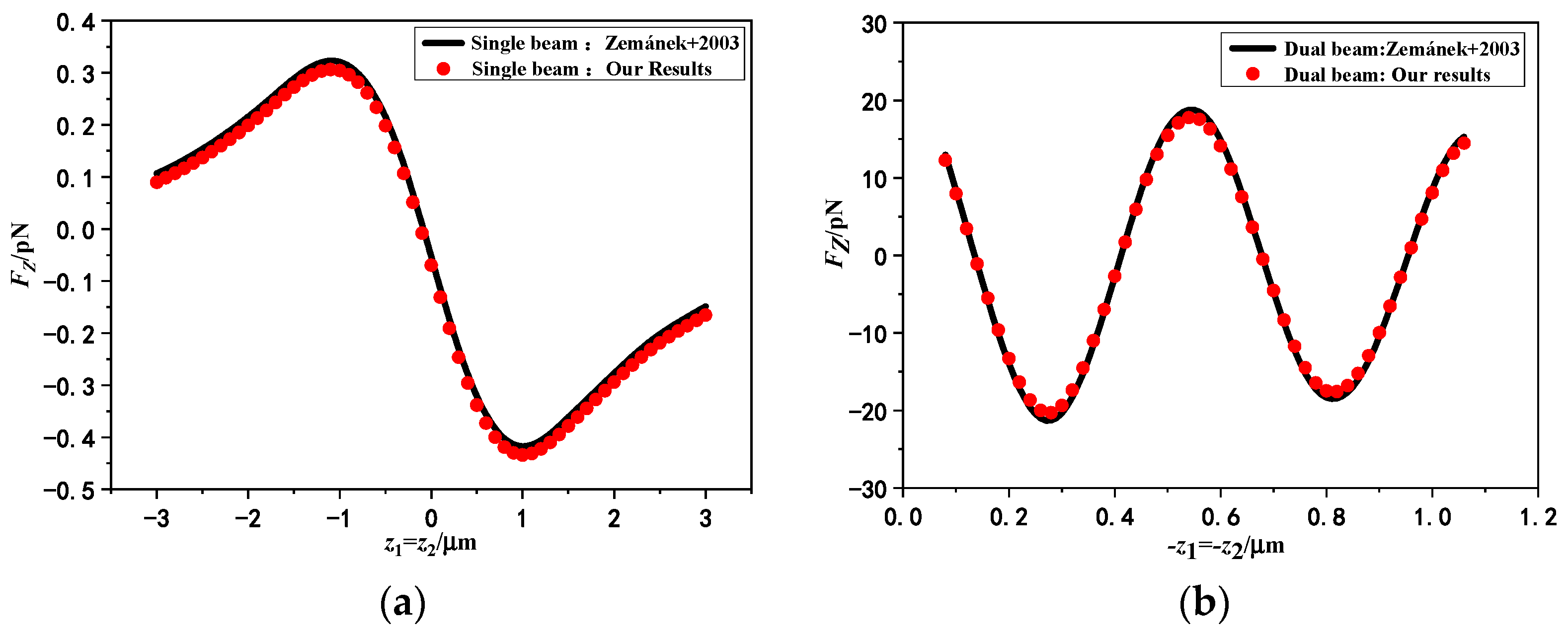
Figure 4 illustrates the distribution of the axial RF with the varying axial position of the beam center acting on the degraded chiral particle by single laser beam and dual laser beams in Figure 4a,b, separately. To prove the correctness of theory and procedure, chiral sphere ( κ = 0 ) is degenerated into non-chiral isotropic sphere. The lines indicate the results calculated in literature [28], and the points indicate the theoretical calculations in this paper. The incident angle of standing wave is: α 1 = 0 °   α 2 = 180 ° and wavelength is 1.064   μ m . The beam center is x 1 = y 1 = 0   x 2 = y 2 = 0 , and the spherical radius is denoted as 80 nm. As shown in Figure 4, we can find that the degraded consequences in this paper coincide well with the literature ones, which indicates the correctness of our procedures and formulas. There are two kinds of forces caused by the interaction between particles and light waves. One is the gradient force caused by the Lorenz effect of EM field acting on particles and makes particles shift in light intensity gradient direction. The other one is scattering force that makes sphere move along the direction of the light wave incidence. The calculation of the axial RF of the beam acting on the particle by using the GLMT is based on the boundary conditions, so it is the resultant of these two forces. As shown in Figure 4a, when the center of the beam moves closer to the particles, there will be a trapping force pointing to the beam center. At this time, the gradient effect is larger than the scattering force, and the particle will be directed to the beam waist center, so as to realize the stable capture of particles in the light field. Compared to the RF generated by the forward single Gaussian beam, the trend of the axial RF generated by the Gaussian standing beams is more complicated in Figure 4b. A number of stable points are created when two relativistic propagating laser beams carry the same amplitude, the same frequency, and a fixed phase difference. This is due to the fact that standing laser beam field can form a periodic structure as in Figure 3, so particles can be trapped at multiple locations. In addition, it can be observed that the axial RF produced by the dual beams is two orders of magnitude larger than that produced by a single Gaussian beam. This is due to the fact that interference introduced by dual beams can lead to extra energy transfer, thus giving the particles higher speed and greater axial RF. This is one of the advantages of dual Gaussian beams over single Gaussian beam in particle capture.
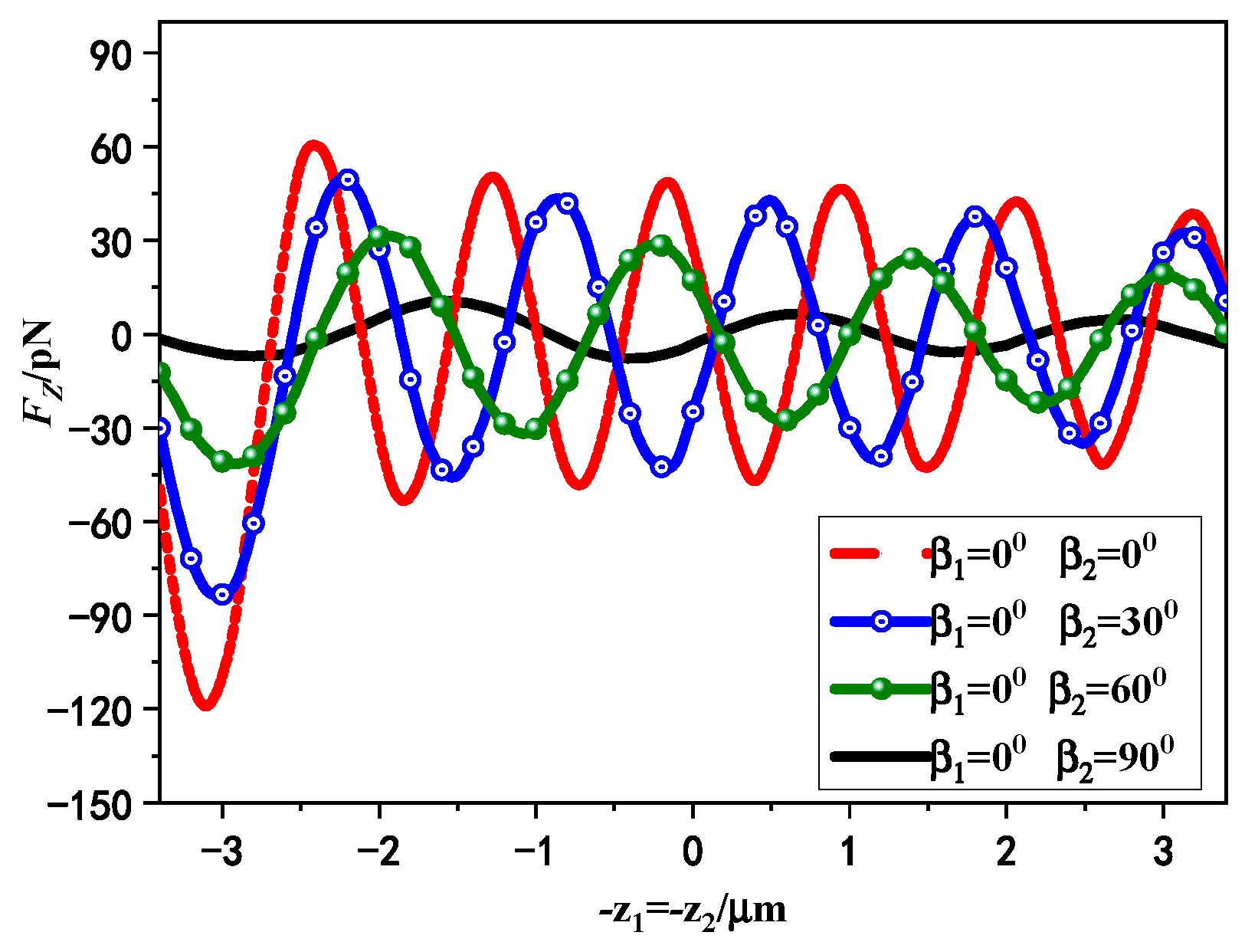
Figure 5 presents the variation curves of the axial RF of standing laser beams on chiral sphere with different linear polarization angles. The dual beams are both x-direction linearly polarized and transmits in the + z ( α 1 = 0 ° ) and z ( α 2 = 180 ° ) directions, separately. The wavelength in the free space is λ = 1064   nm and the waist width is w 01 = w 02 = 0.8   μ m . We set the first laser beam with the polarization angle β 1 = 0 ° , the corresponding angle of the second laser beam is taken as β 2 = 0 ° ,   30 ° ,   60 ° ,   90 ° , respectively. The other parameters used in the calculation are as follows: the sphere radius is a = 800   nm , the refractive index is n = 2 , the chirality is selected κ = 0.3 . Note that the phase difference is zero in Figure 5 but not 3 π / 2 , where 3 π / 2 is a simulation relative to Figure 4b. A great deal of calculations indicate that the equilibrium point position has a little shift on the whole, but the relative relationships of equilibrium point position are not changed when the phase difference is not zero. In the remainder of this paper, the effect of phase difference will not be discussed. As shown in Figure 5, axial RF presents maximally if the polarized directions of standing laser beams are identical. This phenomenon is consistent with the results in Ref. [38], which indicates that the axial RF exerted on particles by standing Gaussian beams is identical when their polarization directions are the same or change synchronously. In other words, the axial RF curve for chiral particles only manifests if the polarized angle changes out of sync. The increasing difference will cause axial RF decreases due to the standing wave field’s influence under distinct polarization conditions. Notably, axial trapping presents smallest if the polarized directions of dual laser beams are perpendicular to each other. Furthermore, it can be observed that with the decrease of the polarization angle difference, more capture points appear, which means that the probability of capturing chiral particles by the standing Gaussian beams is enhanced.
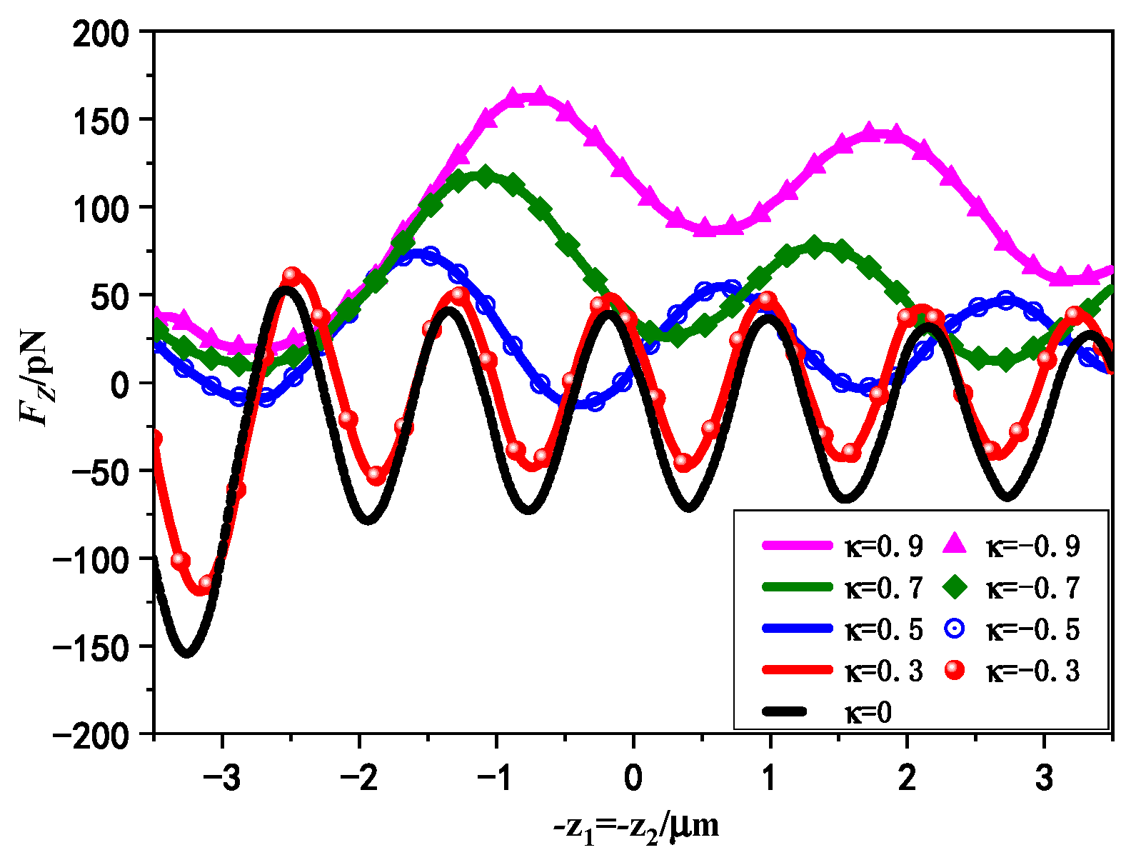
Figure 6 gives the variation curves of axial RF on chiral particle with different chirality parameters induced by standing laser beams. The variables here are consistent with Figure 5 except that the chirality parameter is denoted as κ = 0 , ± 0.3 , ± 0.5 , ± 0.7 , ± 0.9 . It can be seen that the curve of the axial RF of chiral particle versus beam center is analogical with a non-chiral sphere. Among the five cases, when the chiral sphere degenerates into that of a non-chiral isotropic sphere ( κ = 0 ), the maximum negative value of the axial RF can be achieved, with a negative slope distribution of zero crossing points at multiple positions. Additionally, the generated axial RF is the same when the chiral parameters are opposite to each other ( κ = ± 0.3 , ± 0.5 , ± 0.7 , ± 0.9 ) for linear polarization incidence. If the sphere shows little chirality, such as when it is κ = ± 0.3 or κ = ± 0.5 , the negative axial RF can also be achieved at multiple axial positions with zero crossing points. This indicates that for non-chiral isotropic medium spheres or chiral medium spheres with small chirality parameters, the axial RF can reach stable trapping points at several positions on the beam axis, where chiral spheres can be axially trapped by Gaussian standing waves. If the chiral sphere carries more chirality, the minimum value of the axial RF will increase until the negative force disappears. The increasing chiral parameters will destroy the rotational symmetry of chiral spheres, resulting in non-stable mechanical equilibrium positions along the axial direction of the standing wave field. As a result, the stability of the trapping force will decrease. This indicates that for Gaussian standing waves with linear polarization, the introduction of chirality parameters will weaken the axial trapping performance of chiral spheres, making it more difficult to manipulate chiral particles with Gaussian standing waves. Therefore, using dual Gaussian waves to achieve axial trapping of chiral spheres is not easier than trapping non-chiral isotropic spheres in general.
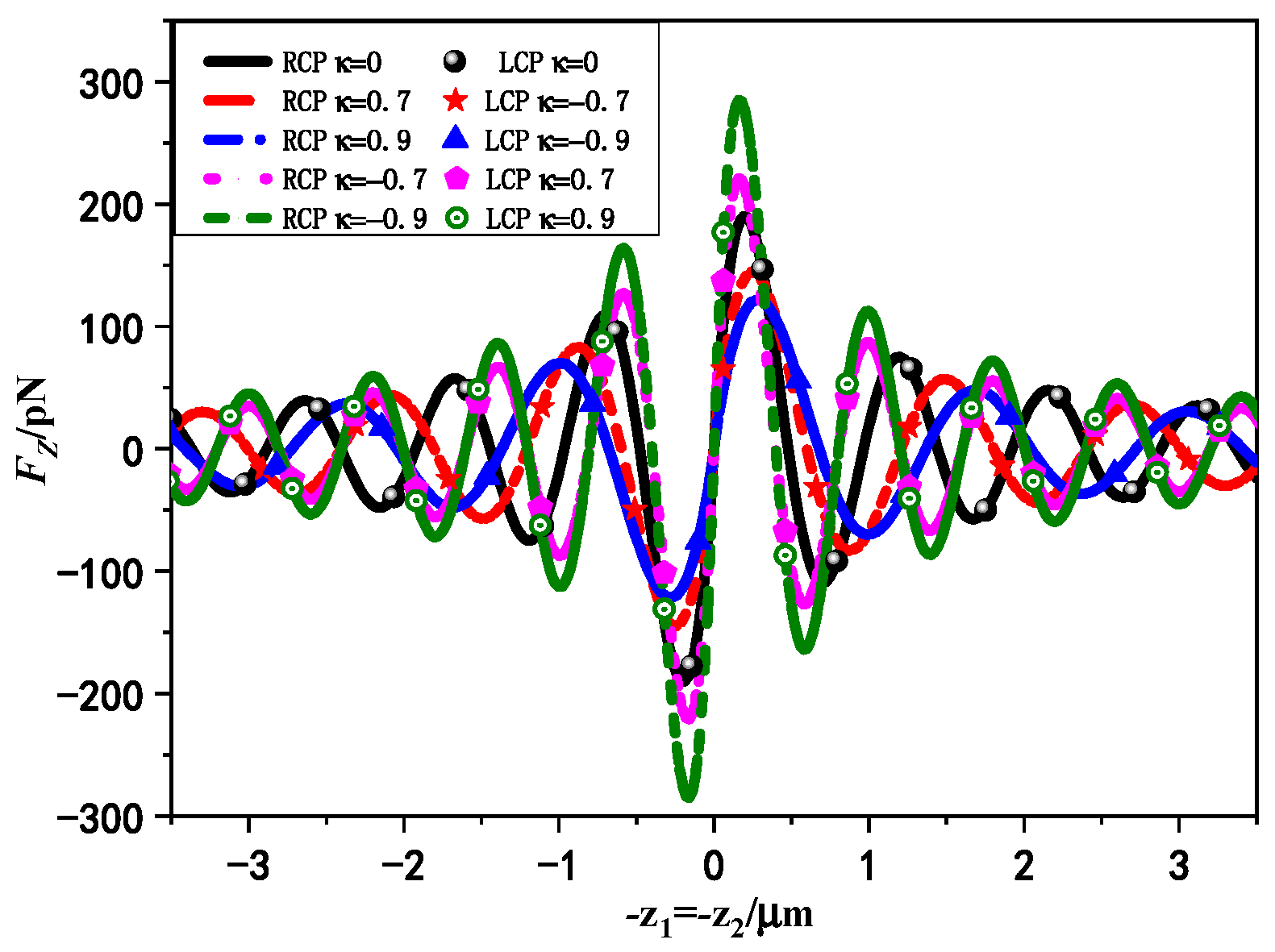
In Figure 7, we give the effect of circular polarization states on axial RF exerted on chiral particle by standing laser beams with varying chirality parameters. The dual Gaussian beams are the same as RCP or LCP incidence, respectively. Other parameters are consistent with Figure 5. It can be observed that the axial RF generated by the dual beams of RCP wave incident on chiral particle with negative chirality are equivalent to that of LCP wave incident with positive chirality. The following relations between the wave numbers of the two polarized waves satisfied k 1 ( κ ) = k 2 ( κ ) , k 1 ( κ ) = k 2 ( κ ) . Based on this symmetry, it can be envisaged that the scattering of chiral particles with opposite chirality parameter κ by RCP or LCP beams is coincident. In both cases, the external intensity distribution of the chiral medium sphere is consistent. Furthermore, we can find that the capture ability of the axis RF will increase with the enhancement of chirality when the RCP standing wave incident chirality is negative and the LCP standing wave incident chirality is positive. Under the situation of the same RCP standing wave illuminate, the chiral medium sphere with negative chirality undergoes a larger axial RF than that with positive chirality, indicating that the axial RF produced by the RCP Gaussian standing wave is larger for the chiral medium sphere with negative chiral parameters. In addition, the distance between the stable capture points of negative chirality particles induced by RCP standing wave on the optical axis is smaller, which means that RCP Gaussian standing wave has greater probability of capturing chiral medium spheres with negative chiral parameters. Therefore, it may be easier to achieve axial trapping of chiral spheres using standing laser beams with suitable circular polarization.
In 
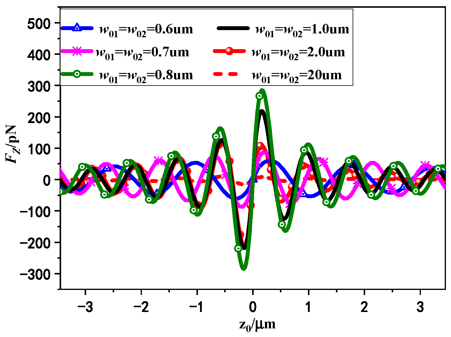
Figure 8, the variation curves of axial RF exerted on chiral particle by Gaussian standing beams with different beam waist width w 01 ( w 02 ) are presented. The dual beams are both RCP waves with the same beam waist width, which are chosen ranges from 0.6   μ m to 20   μ m . The chiral parameter is denoted as κ = 0.9 . Other parameters are consistent with Figure 5. As shown in Figure 8, we can observe that if the beam waist width increases, the trapping force and optical well depth will enlarge accordingly, and reach their peak values around the origin when the waist width is in the range of 0.6   μ m w 01 ( w 02 ) 0.8   μ m . At this point, the spherical size is greater than the beam waist width; with the increase of beam waist width, the number of photons carried by the double beam will increase, and the scattering effect will increase, which is represented by the increase of the magnitude of the axial RF, and meanwhile the dual Gaussian beams can realize stronger trapping ability for chiral sphere. However, when the waist width is increased to w 01 ( w 02 ) > 1   μ m , the axial RF begins to decrease and continues to decline. At this time, the beam waist width increases to exceed the spherical size, the convergent degree of the double beams in the z axis weakens and the gradient force becomes smaller, which is manifested as the magnitude of the axial RF decreases continuously. Until the Gaussian standing beams reduced to the plane standing waves when the beam waist width reach 20   μ m , the gradient force decreases and the axial RF amplitude is reduced, which means that the ability of standing laser beams to trap chiral particles will be affected to some extent. In addition, the computational results also show that when the waist width is compared with the particle size, the position of the equilibrium point moves slightly overall with the change of the waist width, which indicates that the influence of waist width on the location of the capture points is negligible.
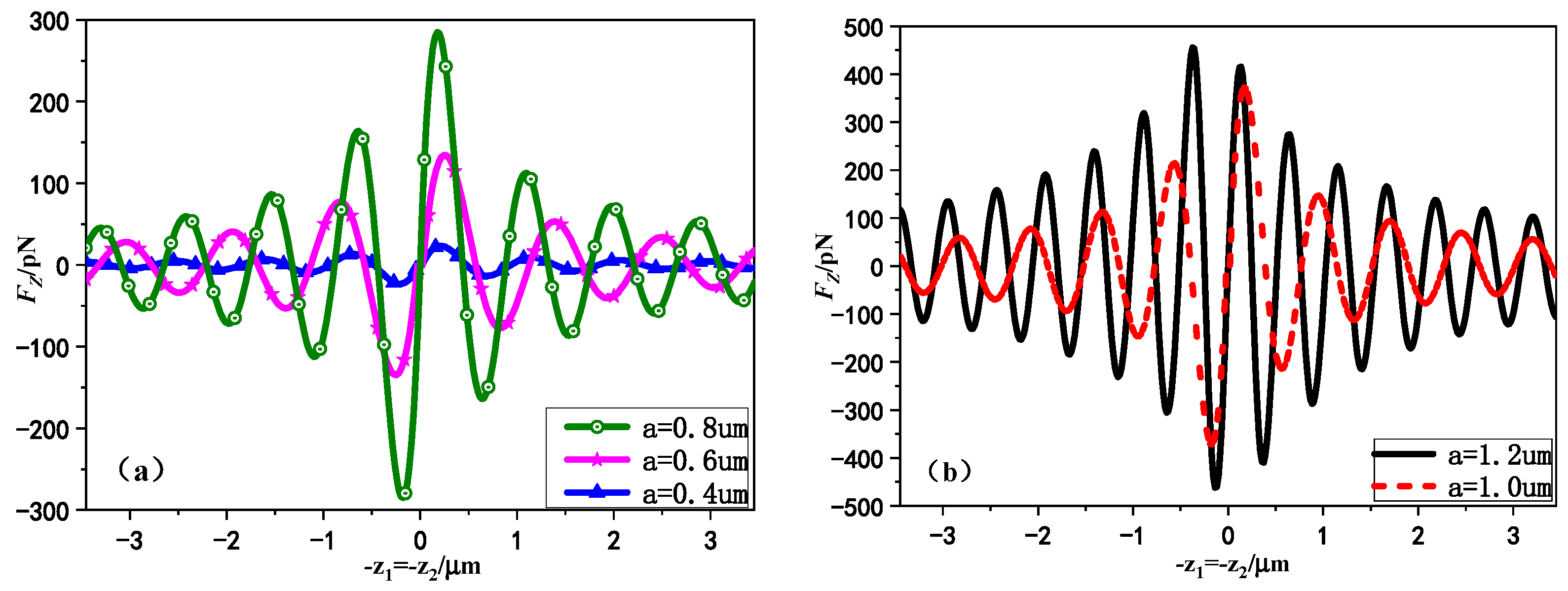
Figure 9 shows the variation curves of the RF on chiral particle with different radius a by Gaussian standing beams. The standing wave consists of dual laser beams transmitting in the + z direction and z direction, respectively, and the dual beams are the same with RCP incident and the waist width is w 01 = w 02 = 0.8   μ m . The relevant parameters are consistent with Figure 8. We chose the chiral sphere radius as 0.4   μ m , 0.6   μ m , 0.8   μ m , 1.0   μ m , 1.2   μ m , respectively, which includes the Rayleigh particles suitable for targets smaller than induced wavelength (e.g., Figure 9a) and the radial optic particles applicable for larger targets (e.g., Figure 9b). It can be observed from Figure 9a,b that there is always a capture position near the center of the beam for the selected chiral sphere of arbitrary radius. This is coincident with the phenomenon that dual relativistic propagating laser beams can create a series of stable points trap. Moreover, it can be seen from Figure 9a,b that the amplitude of the axial RF will gradually increase with the increase of chiral particle size, the axial trapping gradient well will increase. In addition, the equilibrium position clearly moves and the distance between the equilibrium points decreases continuously with the increase of the particle radius. In addition, it can be seen from Figure 9b that the standing wave field can provide larger axial gradient and more stable capture probability for large-size chiral spheres, which makes it easier to be captured by standing laser beam.
In 
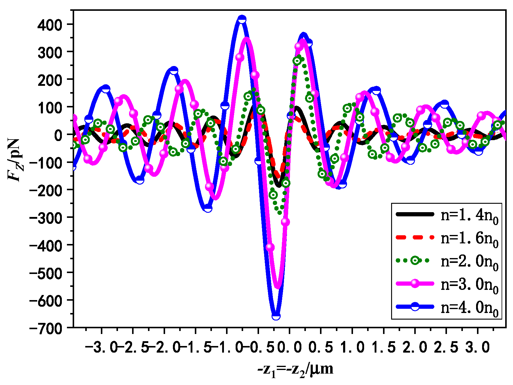
Figure 10, the variation curves of axial RF on chiral particle by Gaussian standing beams with the position of the beam center for different particle refractive index n are presented. The dual beams are coincident with RCP incidence and the waist width is w 01 = w 02 = 0.8   μ m . The spherical refractive indices are selected as 1.4 n 0 , 1.6 n 0 , 2.0 n 0 , 3.0 n 0 , 4.0 n 0 , respectively. The rest of the parameters are consistent with Figure 8. It can be seen from Figure 10, as the particles refractive index increases, the axial RF on the chiral sphere by Gaussian standing beams will increase. Meanwhile, the distance between equilibrium points will increase, which indicates that the particle capture position becomes less. That is, chiral spheres with larger particle refractive indices become more likely to be stably captured by laser standing beams, while the smaller refractive index particles can achieve the sub-stable manipulation in more positions of the optical axis. In addition, it can be found that as the refractive index increases, the Gaussian standing beams have a larger capture negative slope in the range 0.8   μ m < z < 0.3   μ m of the optical axis, which indicates that the particles in this range are being trapped more tightly by standing laser beams. This may be due to the particle refractive index being much higher than the circumambient environment one, causing the force generated by the optical potential well to be much greater than the scattering force, and the chiral particle with high refractive indices can be better trapped when it is in the region close to the standing laser beam focus.
In 
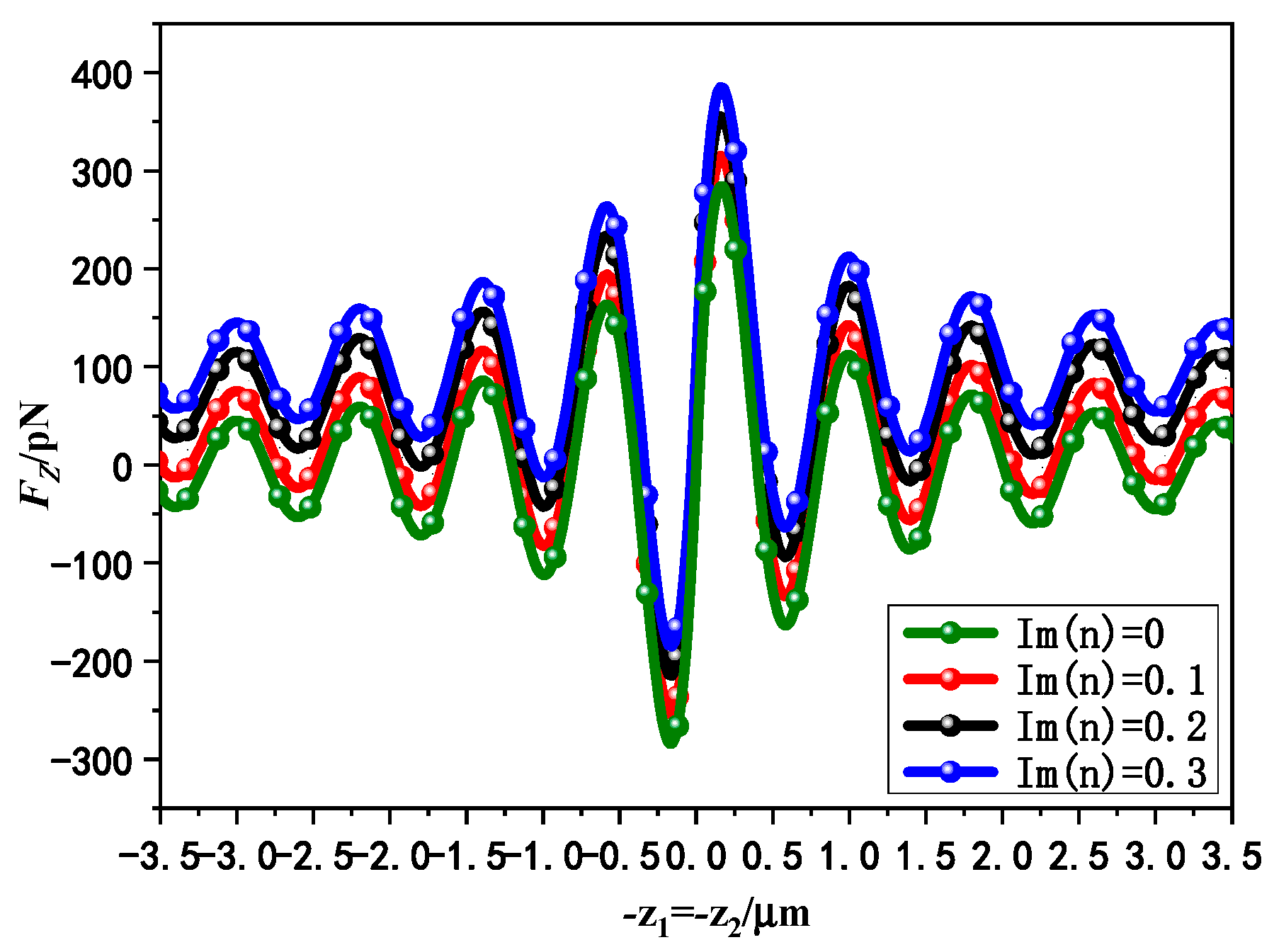
Figure 11, the variation curves of axial RF on chiral particle by dual Gaussian beams with different particle losses ( Im ( n ) ) are presented. We take the range of refractive index imaginary part Im ( n ) from 0 to 0.3, and keep other arguments consistent with Figure 8 except that waist width is w 01 = w 02 = 0.8   μ m . It can be seen from Figure 11 with the refractive index imaginary part Im ( n ) increases, the position of the trapping point does not change significantly, which indicates that the probability of trapping chiral spheres is not affected by the introduced particle losses. In addition, the magnitude of axial RF on the chiral sphere by standing Gaussian beams will increase with the increase of the particle loss. However, the modulus of the negative trapping force exerted on chiral particles starts to decrease when the loss increases. This is because the number of photons absorbed by the chiral particles will increase when the loss increases, which leads to the fact that the scattering force gets bigger, resulting in a smaller trapping probability of particles by dual beams. It can also be found that with the increase of the chiral particle loss, the capture force on the particles far from the beam center begins to decrease until it disappears. At this time, the single beam will lose its trapping ability on chiral particles. However, under the same conditions, the standing wave trap formed by the dual Gaussian beams can still achieve axial trapping of high loss chiral particles. This is also the advantage of the dual Gaussian beams over the single beam in capturing chiral particles.
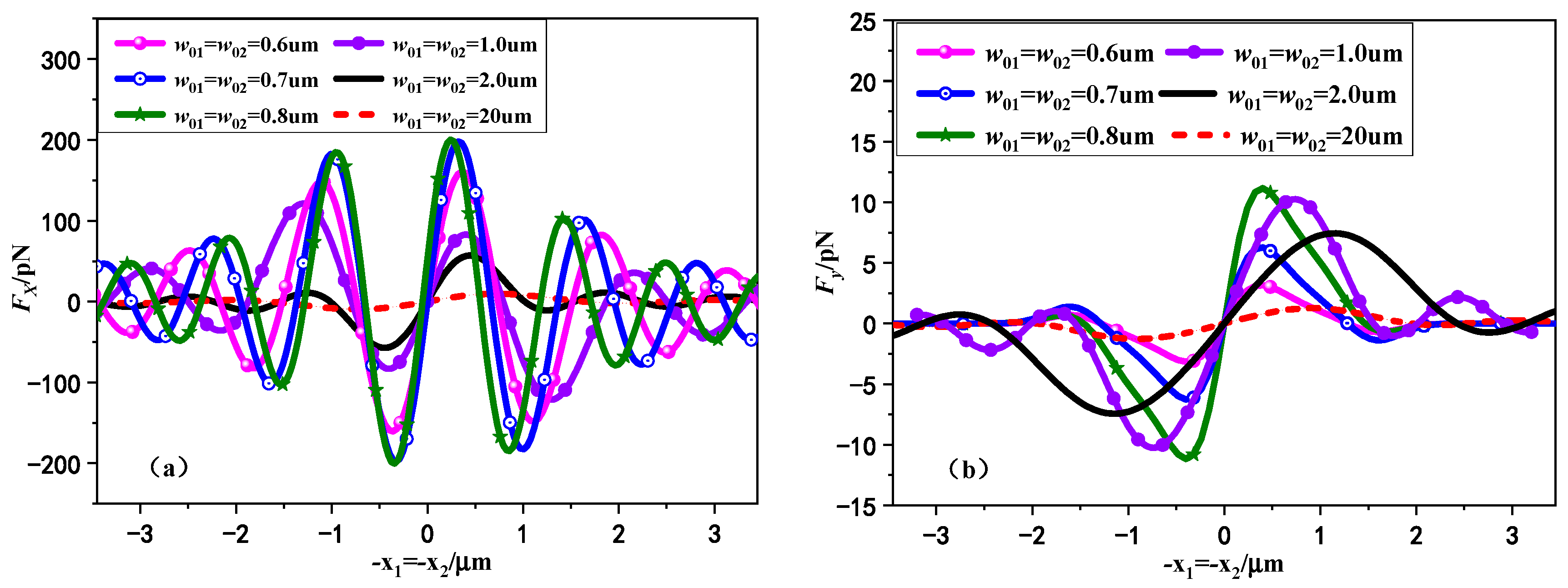
In Figure 12, the variation curves of lateral RF F x and F y on chiral particle by Gaussian standing beams with the different waist width w 01 ( w 02 ) are presented. Both beams are RCP incidence. The waist widths of the two beams are chosen to be the same. The relevant waist width here is selected as 0.6   μ m ,   0.7   μ m ,   0.8   μ m ,   1.0   μ m ,   2.0   μ m , and 20   μ m , respectively. The rest of the parameters remain the same as Figure 9. As shown in Figure 12, the transverse trapping phenomenon of chiral sphere is distinguished from that of achiral particle. For the general non-chiral isotropic dielectric sphere located on the x -axis, the lateral RF component F y is always zero. However, we can observe from Figure 12b that the lateral RF F y of chiral sphere applied in the x direction is not zero, and its absolute value will increase first and then decrease with the increase of the waist width. This is due to the interaction of two polarized waves in the chiral sphere, which indicates that the chiral sphere does not only move along the x -axis in the transverse ( x o y plane), but deviates from the x -axis due to transverse forces in the y direction due to the combined transverse RF of the beam. In addition, it can be found that if the particle radius is comparable to the laser width, the magnitude of transverse RF F y of small beam waist width is usually a few orders smaller than F x , resulting in negligible influence of F y compared with F x . Therefore, selecting the appropriate waist width of the standing beams can produce more stable transverse capture of chiral particles.

5. Conclusions

The radiation characteristics of chiral spheres under the illumination of dual laser beams are researched in this paper. The theory and procedure are validated by comparison with the previous literature. The effects of a variety of parameters, for example, beam polarization form, waist width, particle radius, chirality parameters, particle refractive index, and material losses on RF, were discussed in detail. Numerical results indicate that in some cases, the introduction of chiral parameters will weaken the axial trap performance of chiral sphere. Thus, using dual Gaussian beams to achieve axial trap of chiral sphere may be more challenging than isotropic spheres. Since standing laser fields produced by dual relativistic propagating laser beams carry the same amplitude, the same frequency, and a constant phase difference can provide more stable capture opportunities, the larger chiral sphere can be better captured by Gaussian standing waves as a fine balance between effect of the variety of parameters of the illuminate standing beams and of the chiral particle. It is shown that the polarization form of the standing beams and the handedness of chiral sphere can apparently affect the trap of chiral sphere, and the axial capture performance of the target with contrary chiral parameter is consistent with the corresponding polarization state. Thus, it is necessary to utilize appropriate circularly polarized Gaussian standing waves to manipulate relevant chiral particles. Moreover, the results show that the standing beams can produce more stable transverse and axial capture of chiral particles if the spherical size is selected comparable to the laser waist width, and the negative trapping force shows that the chiral spherical particle with high refractive index and low loss is more desirable for stable capture. In addition, it is found that the stable capture point interval can be adjusted by changing the geometry of the object and the parameters of the induced laser beam. These results show that Gaussian standing beams with a smaller polarization angle difference make it easier to achieve multiple captures, whereas the larger refractive indices of chiral particles reduce it. The theoretical and numerical codes proposed in this article can provide useful tools for experimental research on manipulating chiral particles with dual or more laser beams, which may provide important insight into the optical controlling of chiral biological cells.

Author Contributions

Conceptualization, J.B. and C.-X.G.; methodology, Z.-S.W.; software, J.B.; validation, J.B.; formal analysis, C.-X.G. writing—original draft preparation, J.B.; writing—review and editing, J.B.; funding acquisition, J.B. and C.-X.G. All authors have read and agreed to the published version of the manuscript.

Funding

This research was funded by the National Natural Science Foundation of China for its support of Grant nos. 62001377, 62101445, the Natural Science Foundation of Shaanxi Province under Grant nos. 2023-JC-QN-0657, 2023-JC-QN-0774, 2022KJXX-95, and 2020JQ-843. Xi’an Association for Science and Technology 959202313013.

Institutional Review Board Statement

Not applicable.

Informed Consent Statement

Not applicable.

Data Availability Statement

Data underlying the results presented in this paper are not publicly available at this time but may be obtained from the authors upon reasonable request.

Acknowledgments

The authors acknowledge the National Natural Science Foundation of China for its support of Grant nos. 62001377, 62101445, the Natural Science Foundation of Shaanxi Province under Grant nos. 2023-JC-QN-0657, 2023-JC-QN-0774, 2022KJXX-95, and 2020JQ-843. Xi’an Association for Science and Technology 959202313013.

Conflicts of Interest

The authors declare no conflict of interest.

References

  1. Ashkin, A. Acceleration and Trapping of Particles by Radiation Pressure. Phys. Rev. Lett. 1970, 24, 156–159. [Google Scholar] [CrossRef] [Green Version]
  2. Ashkin, A. Applications of laser radiation pressure. Science 1980, 210, 1081–1088. [Google Scholar] [CrossRef] [PubMed]
  3. Leach, J.; Howard, D.; Roberts, S.; Gibson, G.; Gothard, D.; Cooper, J.; Shakesheff, K.; Padgett, M.; Buttery, L. Manipulation of live mouse embryonic stem cells using holographic optical tweezers. J. Mod. Opt. 2009, 56, 448–452. [Google Scholar] [CrossRef]
  4. Molloy, J.E.; Dholakia, K.; Padgett, M.J. Optical tweezers in a new light. J. Mod. Opt. 2003, 53, 357–364. [Google Scholar] [CrossRef]
  5. Xin, H.; Li, Y.; Liu, Y.-C.; Zhang, Y.; Xiao, Y.F.; Li, B.J. Optical Forces: From Fundamental to Biological Applications. Adv. Mater. 2020, 32, 2001994. [Google Scholar] [CrossRef]
  6. Corsetti, S.; Dholakia, K. Optical manipulation: Advances for biophotonics in the 21st century. J. Biomed. Opt. 2021, 26, 070602. [Google Scholar] [CrossRef]
  7. Favre-Bulle, I.A.; Stilgoe, A.B.; Scott, E.K.; Halina, R.D. Optical trapping in vivo: Theory, practice, and applications. Nanophotonics 2019, 8, 1023–1040. [Google Scholar] [CrossRef] [Green Version]
  8. Santiago-Cordoba, M.A.; Cetinkaya, M.; Boriskina, S.V.; Vollmer, F.; Demirel, M.C. Ultrasensitive detection of a protein by optical trapping in a photonic-plasmonic microcavity. J. Biophotonics 2012, 5, 629–638. [Google Scholar] [CrossRef] [PubMed] [Green Version]
  9. Brunetti, G.; Sasanelli, N.; Armenise, M.N.; Ciminelli, C. Nanoscale optical trapping by means of dielectric bowtie. Photonics 2022, 9, 425. [Google Scholar] [CrossRef]
  10. Parlatan, U.; Başar, G. Sorting of micron-sized particles using holographic optical Raman tweezers in aqueous medium. J. Mod. Opt. 2019, 66, 228–234. [Google Scholar] [CrossRef]
  11. Jordan, P.; Clare, H.; Flendrig, L.; Leach, J.; Cooper, J.; Padgett, M. Permanent 3D microstructures in a polymeric host created using holographic optical tweezers. J. Mod. Opt. 2004, 51, 627–632. [Google Scholar] [CrossRef]
  12. Tang, Q.; Liu, P.; Tang, S. Rotational manipulation of massive particles in a 2D acoustofluidic chamber constituted by multiple nonlinear vibration sources. Chin. Phys. B 2022, 31, 044301. [Google Scholar] [CrossRef]
  13. Conteduca, D.; Brunetti, G.; Pitruzzello, G.; Tragni, F.; Dholakia, K.; Krauss, T.F.; Ciminelli, C. Exploring the limit of multiplexed near-field optical trapping. Acs Photonics 2021, 8, 2060–2066. [Google Scholar] [CrossRef]
  14. Barton, J.P.; Alexander, D.R.; Schaub, S.A. Theoretical determination of net radiation force and torque for a spherical particle illuminated by a focused laser beam. J. Appl. Phys. 1989, 66, 4594–4602. [Google Scholar] [CrossRef]
  15. Yang, A.H.J.; Moore, S.D.; Schmidt, B.S.; Klug, M.; Lipson, M.; Erickson, D. Optical manipulation of nanoparticles and biomolecules in sub-wavelength slot waveguides. Nature 2009, 457, 71–75. [Google Scholar] [CrossRef]
  16. Padgett, M.; Bowman, R. Tweezers with a twist. Nat. Photonics 2011, 5, 343–348. [Google Scholar] [CrossRef]
  17. Wang, Z.L.; Yin, J.P. Radiation forces on a three-level atom in the high-order Bessel beams. Chin. Phys. B 2008, 17, 2466–2477. [Google Scholar]
  18. Kiselev, A.D.; Plutenko, D.O. Optical trapping by Laguerre-Gaussian beams: Far-field matching, equilibria, and dynamics. Phys. Rev. A 2016, 94, 013804. [Google Scholar] [CrossRef]
  19. Zang, Y.C.; Lin, W.J.; Su, C.; Wu, P.F. Axial acoustic radiation force on an elastic spherical shell near an impedance boundary for zero-order quasi-Bessel-Gauss beam. Chin. Phys. B 2021, 30, 044301. [Google Scholar] [CrossRef]
  20. Dong-Feng, B.; Chang-Chun, H.; Jun-Feng, H.; Yi, W. Variational solutions for Hermite–Gaussian solitons in nonlocal nonlinear media. Chin. Phys. B 2009, 18, 2853. [Google Scholar] [CrossRef]
  21. Ng, J.; Lin, Z.; Chan, C.T. Theory of optical trapping by an optical vortex beam. Phys. Rev. Lett. 2010, 104, 103601. [Google Scholar] [CrossRef] [Green Version]
  22. Liu, X.; Sun, C.; Deng, D. Propagation properties and radiation force of circular Airy Gaussian vortex beams in strongly nonlocal nonlinear medium. Chin. Phys. B 2021, 30, 024202. [Google Scholar] [CrossRef]
  23. Xia, H.G.; Yi-Pin, H. Scattering of bi-sphere arbitrarily illuminated by a single beam and a dual beam. Acta Phys. Sin. 2010, 59, 2434–2442. [Google Scholar]
  24. Ashkin, A.; Dziedzic, J.M. Optical levitation by radiation pressure. Appl. Phys. Lett. 1971, 19, 283–285. [Google Scholar] [CrossRef]
  25. Visscher, K.; Gross, S.P.; Block, S.M. Construction of multiple-beam optical traps with nanometer-resolution position sensing. IEEE J. Sel. Top. Quantum Electron. 1996, 2, 1066–1076. [Google Scholar] [CrossRef] [Green Version]
  26. Zemánek, P.; Jonáš, A.; Šrámek, L.; Liška, M. Optical trapping of Rayleigh particles using a Gaussian standing wave. Opt. Commun. 1998, 151, 273–285. [Google Scholar] [CrossRef]
  27. Zemánek, P.; Jonáš, A.; Liška, M. Simplified description of optical forces acting on a nanoparticle in the Gaussian standing wave. J. Opt. Soc. Am. A 2002, 19, 1025–1034. [Google Scholar] [CrossRef] [Green Version]
  28. Zemánek, P.; Jonáš, A.; Jákl, P.; Ježek, J.; Šerý, M.; Liška, M. Theoretical comparison of optical traps created by standing wave and single beam. Opt. Commun. 2003, 220, 401–412. [Google Scholar] [CrossRef]
  29. Gauthier, R.C.; Frangioudakis, A. Optical levitation particle delivery system for a dual beam fiber optic trap. Appl. Opt. 2000, 39, 26–33. [Google Scholar] [CrossRef]
  30. Ren, K.F.; Greha, G.; Gouesbet, G. Radiation pressure forces exerted on a particle arbitrarily located in a Gaussian beam by using the generalized Lorenz-Mie theory, and associated resonance effects. Opt. Commun. 1994, 108, 343–354. [Google Scholar] [CrossRef]
  31. Gouesbet, G.; Lock, J.A. Rigorous justification of the localized approximation to the beam-shape coefficients in generalized Lorenz–Mie theory. II. Off-axis beams. J. Opt. Soc. Am. A 1994, 11, 2516–2525. [Google Scholar] [CrossRef]
  32. Cizmar, T.; Garces-Chavez, V.; Dholakia, K.; Zemanek, P. Optical trapping in counter-propagating Bessel beams. Opt. Trapp. Opt. Micromanipulation 2004, 5514, 643–651. [Google Scholar]
  33. Casaburi, A.; Pesce, G.; Zemánek, P.; Sasso, A. Two-and three-beam interferometric optical tweezers. Opt. Commun. 2005, 251, 393–404. [Google Scholar] [CrossRef]
  34. van der Horst, A.; van Oostrum, P.D.J.; Moroz, A.; van Blaaderen, A.; Dogterom, M. High trapping forces for high-refractive index particles trapped in dynamic arrays of counterpropagating optical tweezers. Appl. Opt. 2008, 47, 3196–3202. [Google Scholar] [CrossRef] [Green Version]
  35. Zhao, L.; Li, Y.; Qi, J.; Xu, J.; Sun, Q. Quasi 3-dimensional optical trapping by two counter-propagating beams in nano-fiber. Opt. Express 2010, 18, 5724–5729. [Google Scholar] [CrossRef]
  36. Ribezzi-Crivellari, M.; Huguet, J.M.; Ritort, F. Counter-propagating dual-trap optical tweezers based on linear momentum conservation. Rev. Sci. Instrum. 2013, 84, 043104. [Google Scholar] [CrossRef] [Green Version]
  37. Zhang, T.; Mahdy, M.R.C.; Dewan, S.S.; Hossain, M.N.; Rivy, H.M.; Masud, N.; Jony, Z.R. Chiral standing waves and its trapping force on chiral particles. arXiv 2018, arXiv:1811.01874. [Google Scholar]
  38. Li, Z.J.; Li, S.; Li, H.Y.; Qu, T.; Shang, Q.C. Analysis of radiation force on a uniaxial anisotropic sphere by dual counter-propagating Gaussian beams. J. Opt. Soc. Am. A 2021, 38, 616–627. [Google Scholar] [CrossRef]
  39. Kordi, M.; Mirsalehi, M.M. Optical chiral metamaterial based on the resonant behaviour of nanodiscs. J. Mod. Opt. 2016, 63, 1473–1479. [Google Scholar] [CrossRef]
  40. Franco-Ortiz, M.; Corella-Madueño, A.; Rosas-Burgos, R.A.; Reyes, J.A.; Avendaño, C.G. Electrically tuned optical reflection band for an artificial helicoidal structure. J. Mod. Opt. 2018, 65, 1994–2005. [Google Scholar] [CrossRef]
  41. Pedro, C. On Chirality and the Universal Asymmetry. Reflections on Image and Mirror Image. By Georges H. Wagnière. Angew. Chem. Int. Edit. 2007, 46, 9143–9144. [Google Scholar]
  42. Lakhtakia, A.; Varadan, V.K.; Varadan, V.V. Scattering and absorption characteristics of lossy dielectric, chiral, nonspherical objects. Appl. Opt. 1985, 24, 4146–4154. [Google Scholar] [CrossRef]
  43. Worasawate, D.; Mautz, J.R.; Arvas, E. Electromagnetic scattering from an arbitrarily shaped three-dimensional homogeneous chiral body. IEEE Trans. Antennas Propag. 2003, 51, 1077–1084. [Google Scholar] [CrossRef]
  44. Yuceer, M.; Mautz, J.R.; Arvas, E. Method of moments solution for the radar cross section of a chiral body of revolution. IEEE Trans. Antennas Propag. 2005, 53, 1163–1167. [Google Scholar] [CrossRef]
  45. Demir, V.; Elsherbeni, A.Z.; Arvas, E. FDTD formulation for dispersive chiral media using the Z transform method. IEEE Trans. Antennas Propag. 2005, 53, 3374–3384. [Google Scholar] [CrossRef]
  46. Kuzu, L.; Demir, V.; Elsherbeni, A.Z.; Arvas, E. Electromagnetic Scattering from Arbitrarily Shaped Chiral Objects Using the Finite Difference Frequency Domain Method. PIER 2007, 67, 1–24. [Google Scholar] [CrossRef]
  47. Gordon, D.J. Mie scattering by optically active particles. Biochemistry 1972, 11, 413–420. [Google Scholar] [CrossRef]
  48. Wu, Z.S.; Shang, Q.C.; Li, Z.J. Calculation of electromagnetic scattering by a large chiral sphere. Appl. Opt. 2012, 51, 6661–6668. [Google Scholar] [CrossRef]
  49. Cui, Z.; Guo, S.; Wang, J.; Wu, F.; Han, Y. Light scattering of Laguerre–Gaussian vortex beams by arbitrarily shaped chiral particles. J. Opt. Soc. Am. A 2021, 38, 1214–1223. [Google Scholar] [CrossRef] [PubMed]
  50. Bai, J.; Ge, C.X.; Wu, Z.S. Stability and dynamics of chiral nanoparticles in lateral optical binding induced by high-order Bessel beams. J. Quant. Spectrosc. Radiat. Transf. 2020, 243, 106824. [Google Scholar] [CrossRef]
  51. Guzatov, D.V.; Klimov, V.V. Chiral particles in a circularly polarised light field: New effects and applications. Quantum Elec. 2011, 41, 526. [Google Scholar] [CrossRef]
  52. Chen, H.; Wang, N.; Lu, W.; Liu, S.; Lin, Z. Tailoring azimuthal optical force on lossy chiral particles in Bessel beams. Phys. Rev. A 2014, 90, 043850. [Google Scholar] [CrossRef]
  53. Du, J.; Yuen, C.H.; Li, X.; Ding, K.; Du, G.; Lin, Z.; Chan, C.T.; Ng, J. Tailoring optical gradient force and optical scattering and absorption force. Sci. Rep. 2017, 7, 18042. [Google Scholar] [CrossRef] [Green Version]
  54. Zheng, H.; Yu, X.; Lu, W.; Ng, J.; Lin, Z. GCforce: Decomposition of optical force into gradient and scattering parts. Comput. Phys. Commun. 2019, 237, 188–198. [Google Scholar] [CrossRef]
  55. Zheng, H.; Li, X.; Jiang, Y.; Ng, J.; Lin, Z.; Chen, H. General formulations for computing the optical gradient and scattering forces on a spherical chiral particle immersed in generic monochromatic optical fields. Phys. Rev. A 2020, 101, 053830. [Google Scholar] [CrossRef]
  56. Jiang, Y.; Chen, H.; Chen, J.; Ng, J.; Lin, Z. Universal relationships between optical force/torque and orbital versus spin momentum/angular momentum of light. arXiv 2015, arXiv:1511.08546. [Google Scholar]
  57. Shang, Q.C.; Wu, Z.S.; Qu, T.; Li, Z.J.; Bai, L.; Gong, L. Analysis of the radiation force and torque exerted on a chiral sphere by a Gaussian beam. Opt. Express 2013, 21, 8677–8688. [Google Scholar] [CrossRef]
  58. Gouesbet, G.; Grehan, G.; Maheu, B. Computations of the gn coefficients in the generalized Lorenz-Mie theory using three different methods. Appl. Opt. 1988, 27, 4874–4883. [Google Scholar] [CrossRef]
  59. Shen, J.; Liu, X.; Wang, W.; Yu, H. Calculation of light scattering of an elliptical Gaussian beam by a spherical particle. J. Opt. Soc. Am. A 2018, 35, 1288–1298. [Google Scholar] [CrossRef]
  60. Geng, Y.L.; Wu, X.B.; Li, L.W.; Guan, B.R. Mie scattering by a uniaxial anisotropic sphere. Phys. Rev. E 2004, 70, 056609. [Google Scholar] [CrossRef] [Green Version]
  61. Brown, A.J. Equivalence relations and symmetries for laboratory, LIDAR, and planetary Müeller matrix scattering geometries. J. Opt. Soc. Am. A 2014, 31, 2789–2794. [Google Scholar] [CrossRef] [PubMed]
  62. Edmonds, A.R. Angular Momentum in Quantum Mechanics; Princeton University Press: Princeton, NJ, USA, 1996; Volume 4. [Google Scholar]
  63. Bohren, C.F. Light scattering by an optically active sphere. Chem. Phys. Lett. 1974, 29, 458–462. [Google Scholar] [CrossRef]
  64. Sarkar, D.; Halas, N.J. General vector basis function solution of Maxwell’s equations. Phys. Rev. E 1997, 56, 1102. [Google Scholar] [CrossRef]
  65. Li, Z.J.; Wu, Z.S.; Shang, Q.C. Calculation of radiation forces exerted on a uniaxial anisotropic sphere by an off-axis incident Gaussian beam. Opt. Express 2011, 19, 16044–16057. [Google Scholar] [CrossRef] [Green Version]
  66. Aden, A.L.; Kerker, M. Scattering of electromagnetic waves from two concentric spheres. J. Appl. Phys. 1951, 22, 1242–1246. [Google Scholar] [CrossRef]
Figure 1. Schematic diagram of chiral particle irradiated by dual Gaussian beams.
Photonics 10 00905 g001
Figure 2. (a) The intermediate system O x 10 y 10 z 10 established parallel to first laser beam coordinate system O x 1 y 1 z 1 . (b) Illuminated angle α 2 and polarized angle β 2 of second laser beam.
Photonics 10 00905 g002
Figure 3. Illustrates the effects of waist width on the electric components of single progressive Gaussian beam and standing Gaussian beam. (ad) The intensity distribution of single Gaussian beam. (The parameters are λ = 1064   nm ,   α = 0 ° ,   x = y = 0 ). (eh) The intensity distribution of Gaussian standing beam. (The parameters are α 1 = 0 ° ,   α 2 = 180 ° ,   x 1 = y 1 = 0 , x 2 = y 2 = 0 ). The waist radii used are: w 1 = 0.6   μ m in (a,e); w 1 = 0.7   μ m in (b,f); w 1 = 0.8   μ m in (c,g) and w 1 = 1.0   μ m in (d,h).
Photonics 10 00905 g003aPhotonics 10 00905 g003b
Figure 4. The axial RF for the degenerated chiral dielectric sphere is compared with the literature [28] results: (a) Comparison of the axial RF of particles irradiated by single laser beam. (b) Comparison of the axial RF of particles irradiated by dual laser beams. ( a = 80   nm , λ = 1.064   μ m , w 0 = 0.75 λ , n 0 = 1.0 , x 1 = y 1 = 0 , x 2 = y 2 = 0 , α 1 = β 1 = 0 ° , α 2 = β 2 = 180 ° , w 01 = w 02 = 0.6   μ m , P 0 = 0.1   w ; The relative refractive index n = 1.19 ; The phase discrepancy 3 π / 2 ).
Photonics 10 00905 g004
Figure 5. The variation curves of the axial RF of standing laser beams on chiral sphere with different linear polarization angles. ( a = 800   nm , λ = 1064   nm , w 01 = w 02 = 0.8   μ m , n 0 = 1.0 , n = 2 n 0 , x 1 = y 1 = 0 , x 2 = y 2 = 0 , α 1 = β 1 = 0 ° , α 2 = 180 ° , m = 1.19 , P 0 = 0.1   w ; The phase discrepancy 0).
Photonics 10 00905 g005
Figure 6. Effect of chirality parameters on axial RF exerted on chiral sphere by linearly polarized Gaussian standing beams. (The parameters used are a = 800   nm , λ = 1064   nm , w 01 = w 02 = 0.8   μ m , n 0 = 1.0 , n = 2 n 0 , x 1 = y 1 = 0 , x 2 = y 2 = 0 , α 1 = β 1 = 0 ° , α 2 = 180 ° , β 2 = 0 ° , m = 1.19 , P 0 = 0.1   w . The phase discrepancy 0).
Photonics 10 00905 g006
Figure 7. The variation curves of axial RF on chiral particle with different chirality parameters induced by circularly polarized standing laser beams. (The parameters used are λ = 1064   nm , a = 800   nm , w 01 = w 02 = 0.8   μ m , n 0 = 1.0 , n = 2 n 0 , x 1 = y 1 = 0 , x 2 = y 2 = 0 , α 1 = β 1 = 0 ° , α 2 = β 2 = 180 ° , m = 1.19 , P 0 = 0.1   w . The phase discrepancy 0).
Photonics 10 00905 g007
Figure 8. The variation curves of axial RF F z on chiral particle with different beam waist widths induced by circularly polarized standing laser beams. ( λ = 1064   nm , a = 800 nm, n0 = 1.0, n = 2n0, x 1 = y 1 = 0 , x 2 = y 2 = 0 , α 1 = β 1 = 0 ° , α 2 = β 2 = 0 ° , m = 1.19 , P 0 = 0.1   w and the phase discrepancy 0).
Photonics 10 00905 g008
Figure 9. The variation curves of axial RF F z on chiral particle with different radius by Gaussian standing beams: (a) small radius chiral particle, (b) large radius chiral particle. (The parameters used are λ = 1064   nm , w 01 = w 02 = 0.8   μ m , n 0 = 1.0 , n = 2 n 0 , x 1 = y 1 = 0 , x 2 = y 2 = 0 , α 1 = β 1 = 0 ° , α 2 = β 2 = 180 ° , m = 1.19 , P 0 = 0.1   w , and the phase discrepancy 0).
Photonics 10 00905 g009
Figure 10. The variation curves of axial RF on chiral particle with different refractive index by Gaussian standing beams. (The parameters used are a = 800   nm , λ = 1064   nm , w 01 = w 02 = 0.8   μ m , n 0 = 1.0 , x 1 = y 1 = 0 , x 2 = y 2 = 0 , α 1 = β 1 = 0 ° , α 2 = β 2 = 180 ° , m = 1.19 , P 0 = 0.1   w , and the phase discrepancy 0).
Photonics 10 00905 g010
Figure 11. The effect of refractive index imaginary loss Im ( n ) on the axial RF by Gaussian standing beams. (The parameters used are a = 800   nm , λ = 1064   nm , w 01 = w 02 = 0.8   μ m , n 0 = 1.0 , x 1 = y 1 = 0 , x 2 = y 2 = 0 , α 1 = β 1 = 0 ° , α 2 = β 2 = 180 ° , m = 1.19 , P 0 = 0.1   w , and the phase discrepancy 0).
Photonics 10 00905 g011
Figure 12. The variation curves of axial RF on chiral particle by Gaussian standing beams with different waist width: (a) lateral radiation F x ; (b) lateral radiation F y . ( a = 800   nm , λ = 1064   nm , n 0 = 1.0 , n = 2 n 0 , x 1 = y 1 = 0 , x 2 = y 2 = 0 , α 1 = β 1 = 0 ° , α 2 = β 2 = 180 ° , m = 1.19 , P 0 = 0.1   w , and the phase discrepancy 0).
Photonics 10 00905 g012
Disclaimer/Publisher’s Note: The statements, opinions and data contained in all publications are solely those of the individual author(s) and contributor(s) and not of MDPI and/or the editor(s). MDPI and/or the editor(s) disclaim responsibility for any injury to people or property resulting from any ideas, methods, instructions or products referred to in the content.

