1. Introduction
The beam tailoring and sensitive control over transient field characteristics (amplitude, phase, and polarization) and spatial degrees of freedom has an important role in THz optics and photonics. Combined with major peculiarities such as high coherency, non-ionizing nature, and transparency in many dielectric materials, the THz spectrum presently holds a growing potential for probing and controlling a variety of complex phenomena. Moreover, boosted by the technological advances in signal generation and detection, THz technologies that allow electromagnetic fields having strong intensity and high repetition rate are of increasing interest.
The intensive control over the amplitude, phase, and polarization states of light are becoming a major field of research in condensed matter physics. Some novel examples include metamaterial- and nanomaterial-based systems, complex experimentation based on light–material, and/or light–light interactions combining diverse pump and probe schemes such as Visible and THz, Infrared and THz, and X-Ray and THz. Recent progress is showing the potential of using high field transients with tailored profiles to achieve a better control over matter by modification of elementary rotational-vibrational excitations, density of states and electronic structures of complex systems, and even intensive acceleration and sensitive manipulation of electron bunches [
1,
2]. For instance, accelerator-based sources can generate ultra-relativistic electron bunches to produce super radiant and coherent radiation. In these novel systems, density modulation at THz frequencies is required to generate the high intensity field emission [
3]. As an important property, the electron bunch triggered THz radiation becomes self-synchronized with other radiation types such as IR and X-rays [
4]. This property allows to use the synchronized THz pulses for electron beam diagnostics to quantify the charge distribution of the electron bunches.
In the last years, there have been a plethora of successful demonstrations of devices for THz beam control, accomplished by use of metamaterials or waveplates and resorting on phase change materials and voltage tunable systems. They include phase shifters based on dielectric metasurfaces with a compound lattice [
5] or on artificial birefringence grating filled with polymer dispersed liquid crystals [
6], accompanied by the polarization-dependent Electromagnetically Induced Transparency (EIT) effect, carrier envelope phase shifter utilizing the ultra-broadband feature of prism waveplates [
7], switchable ultrathin quarter waveplate using an active phase-change metasurface [
8], to mention a few. As a recent example, Hibberd et al. demonstrated the use of using polarization-controlled THz pulses to achieve linear acceleration of relativistic electron beams [
9]. In the proposed setup, the phase shifter plate is one of the crucial components of the system, where the controlled and sensitive manipulation of the THz pulse into a quasi-TEM
01 polarization state plays a key role to achieve the necessary coupling with the longitudinal accelerating mode of the beam guide used. In the experimental scheme, a polytetrafluoroethylene (PTFE) phase-shifter plate is utilized, where the phase shift is achieved due to the thickness difference in between the two sub-areas of the component. This approach inevitably gives a time delay in between the two wave fronts and may have a strong negative influence on the coupling and mode matching efficiency, for possible applications where higher sensitivity might be desired—for instance, in FEL-assisted IR/THz and X-Ray/THz pump and probe experiments.
In this work, we present the study, fabrication, and experimental characterization of an all-dielectric phase shifter plate component. The manufactured component provides a high-quality phase retardation in between the two planes. Moreover, the simplistic and flexible design enables selection of the plane of symmetry around the chosen central axes of choice, without inducing any temporal shifts in between the two sections of the beam fronts.
2. Materials and Methods
It is well known that when the source wavelength is far larger than the individual component dimensions of a device, the traversing electromagnetic signal perceives the structure as a homogenized system with effective electro-optical parameters. In such a way, one may manipulate an optical beam with ease, solely arranging materials in a periodic sequence and achieving high birefringent media even with relatively low dielectric constant materials (like polymers and air). The birefringence associated with the use of periodic structures is the so-called “form birefringence” [
10] and has been widely applied to create various devices: waveplates, filters, and even q-plates [
10,
11,
12], to mention some.
In the sub-THz window, geometrical limits are in the millimeter scale; therefore, additive manufacturing techniques based on commercially available three-dimensional (3D) printing technologies are gaining popularity as a promising cost-effective approach for fast prototyping and manufacturing of novel passive or hybrid optical elements.
The achievable “form birefringence” for a given air-dielectric groove system can be analytically calculated using the second-order effective medium theory (EMT) solutions [
13]:
where
is the period given by the structure with separation widths L
1 and L
2, and the volume fractions of the components having equal thicknesses are given by
and
. In the above equations,
and
are the quasi-static refractive index for the electrical field parallel and perpendicular, respectively.
We previously reported that the experimentally extracted parameters show a very good agreement with the second-order solutions [
12]. For a given index of refraction (air, n
1 = 1; polymer ABS, n
2~1.68), one may estimate a birefringence as high as
.
With the advent of innovative 3D printing systems, there has been recently growing research on advanced composite materials for use as filaments for 3D printing, to achieve desired chemical, physical, and mechanical properties [
14]. Therefore, with the new generation of printing materials, it is expected to reach even higher levels of form birefringence. While many of polymer-based commercial filaments have similar index of refraction levels around 1.5 ÷ 2.0, the absorption characteristics at THz frequencies may vary by orders of magnitude [
15]. The possible use of some promising polymers with super low absorption coefficients over a much large frequency range, such as cyclic olefin copolymers and high-density polyethylene [
16,
17], will surely improve the frequency band and transmission characteristics of the proposed design.
In this work, we have used the widely available ABS filament as a cost-effective solution. The melting temperatures of many commercial filaments are in the orders of few hundred of Celsius. In such materials, induced thermo-mechanical degradations under repeated electromagnetic heating may modify their electro-optical properties [
18]. Due to the non-ionizing properties of the THz field, a high level of energy transfer usually does not occur in this frequency range, especially with standard sources reaching only a few µJ of energy per pulse. On the contrary, FEL-assisted high-field THz sources may achieve mJ level of average pulse energies and induce polymer morphological changes [
19] under super focused conditions, altering the electro-optical properties of the polymer and as a consequence the design frequencies and parameters. Nevertheless, when compared to the optical regime, even under collimated radiation, the beam irradiance will reduce by more than five orders of magnitude in the THz region, making very realistic the easy adaptation of 3D-printed polymer-based optical elements for advanced FEL-assisted high-field applications in this frequency window.
The designed phase shifter consists of two separate quarter wave(λ/4) plates with 90° relative angle orientation in between them. The wave plate sections composing the device are designed with form birefringent properties following Equations (1) and (2) for alternating layers of ABS and air with equidistant interface separations of 400 µm within manufacturing limits.
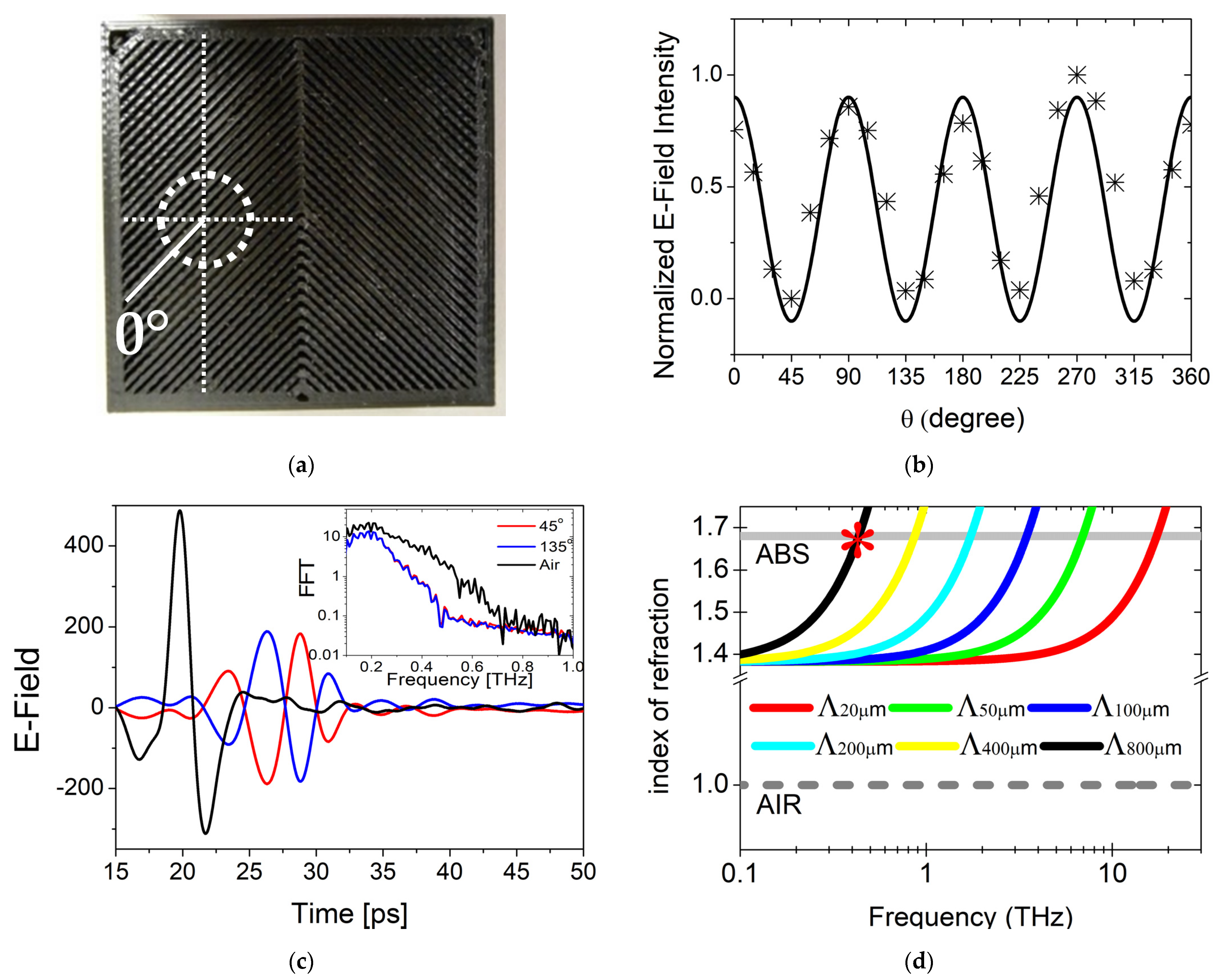
We have realized the designed THz phase shifter plate by using a commercial 3D printer (3D DREMEL
® DigiLab 3D45, Bosch, Leonberg, Germany) by melt extruding ABS filaments (ECO-BLA-01). A picture of the phase shifter, having dimensions 4 × 4 cm
2, is shown in
Figure 1a. The device is realized with a final layer thickness of 4 mm. As seen from the form birefringence calculations (Equations (1) and (2)), the device thickness does not have an effect on the index of refraction characteristics of the device. The relatively thick layer deposition was chosen to minimize the unavoidable defects occurring within the melt extruded filament. Even if they are on a μm scale, defects can create unwanted scattering inside the device and reduce the efficiency of the phase plate. Unfortunately, the removal of scattering effects comes at the expense of a relatively high attenuation of the total signal transmittance in the given frequency range, in the order of 10 dB with respect to the reference signal. The Fast Fourier Transform spectra of the transmitted and the reference signal are shown in the inset of
Figure 1c. Of course, a larger signal passing through the device can be certainly obtained using printing technologies with better spatial resolution.
3. Measurements and Results
The transmission properties and the phase response of the λ/4 plate are characterized using a standard Time Domain Spectroscopy (TDS) in transmission mode. Additionally, the full position-dependent electric field maps of the THz beam propagating through the device are obtained by a raster scan imaging routine.
Measurements are carried out with a commercial THz time domain spectrometer (TERA K-15, Menlo Systems, Planegg, Germany). A standard transmission geometry is used with four TPX lenses first collimating and then focusing the signal, producing a beam spot of approximately 5 mm, much larger than the periodicity of the structures used. Two dipole photo-conducting antennas (PCA) having linear polarization are employed for the emission and detection of the THz signal. The electric field is acquired in a time domain interval of 120 ps. The linearly polarized emitted signal is split into EX and EY projections passing through polarization optics. The EX component of the transmitted field is acquired by placing the emitter and the detector antenna polarization in the same direction, whereas the signal transmitted through the device in perpendicular polarization (the EY component) is attained by rotating the PCA detector by 90° with respect to the PCA emitter.
We first measured the transmission properties (amplitude and phase of the electric field) of the single waveplate composing the device, by rotating the structure with 15° steps with respect to the center of a single section. The device is placed on a computer-controlled rotational stage, and the center section of one plate section is placed concentric to the rotation axis of the stage. In
Figure 1a, the measurement center position is shown with a white circle, and the measurement starting point when the device structure is parallel to the impinging beam polarization direction is displayed as a white line. This position coincides with the starting 0° azimuthal angle shown in the plot of
Figure 1b.
Transmitted time domain electric field profiles for the E
Y components, corresponding to 45° and 135° azimuthal angles, are shown in
Figure 1c. It is worth mentioning that, differently from a standard PTFE phase-shifter plate, the device thickness is constant in between the two subsections, so that the phase-shifted components of the wave front do not produce any time delay as clearly observed from the TDS waveforms. The experimentally observed frequency domain analysis shows that the realized device gives a relatively wide frequency response but is upwardly limited to 0.8 THz (
Figure 1c, inset). It is important to note that, in case of devices realized using 3D printing, scattering and wave-guiding effects are the dominant factor limiting the operational bandwidth of the device, since the periodicity exceeds the impinging signal wavelength. The frequency limit of the device can be estimated by calculating the intersection point of the extracted index of refraction (using second-order EMT solutions) with the index of refraction of the polymer used.
In this work, within the capacity of the printer used, we have achieved a phase shifter showing 400 GHz bandwidth. Ultra-high resolution commercially available printers are capable to reach optical resolutions up to 2 µm [
20,
21]. For demonstration, the possible frequency bandwidth upper limits achievable for moderate periodicities (20–800 µm) using new generation printing technologies are plotted in
Figure 1d. It is fascinating that, for a moderate periodicity of 20 µm, an ultra large bandwidth up to 15 THz is easily viable, that can be further widened to approximately 80 THz for a periodicity of 4 µm. As the device responses a 180° phase shift in between the 45° and 135° degrees of device orientation, it is confusing to the eye to depict the transmittance behavior of an ideal quarter wave plate immediately; for this reason, the transmittance of an Ideal λ/4 plate, given by
, is plot together with the normalized (from 0 to 1 relative values) electric field intensities. As shown in
Figure 1b, the E-field maximum is achieved at
steps starting from 45° such that E-field intensities measured depict the standard behavior for a λ/4 wave plate and can provide a simple roadmap to visualize the expected response from more complicated geometries.
After this first characterization, the device is placed on a computer controlled two-axis positioner to acquire the spatial-dependent electric field of the THz beam propagating through the device by using a standard raster scan routine and covering the total surface area (4 × 4 cm2) with 500 µm steps.
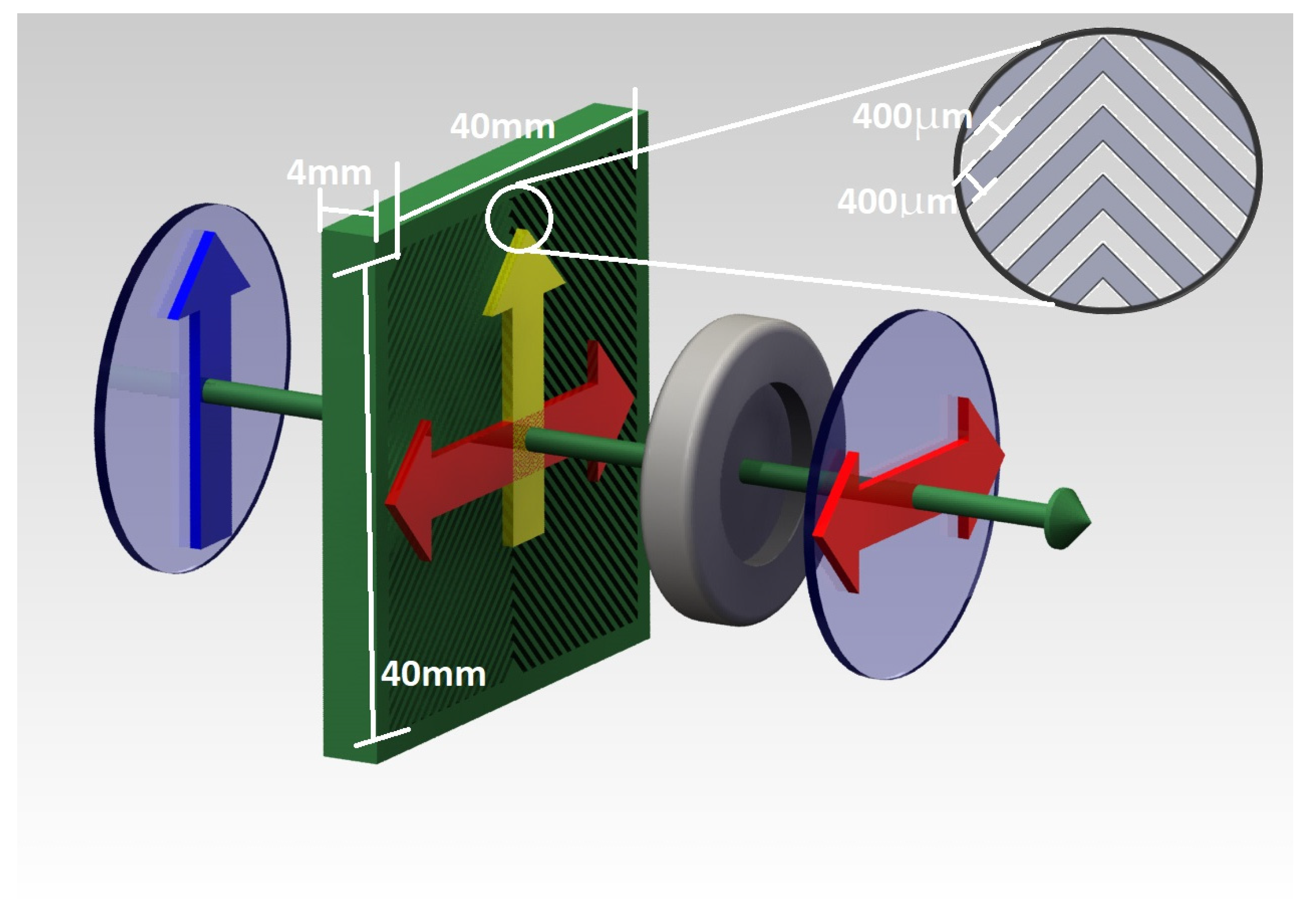
The working principle of the designed phase shifter is schematically shown in
Figure 2. The PCA generates the THz beam with linear polarization (E
X), shown with a blue arrow. Upon passing through the device, the E-field splits in two polarization components (E
X and E
Y or, with different notation, “s” and “p” states, shown as yellow and red arrows, respectively). While the E
X component has no phase retardation as experimentally observed from the transferred time domain signals (shown with yellow arrow), the E
Y component (shown with red arrow) shows a quasi-ideal phase retardation in between the two sections of the wave plate.
To acquire the phase retarded component, the E
X component of the impinging beam is removed by using a (wire grid) polarizer (the grey component in
Figure 2), which is placed in front of the proposed wave plate structure. This limits the phase maps shown in
Figure 3 to a circular area having the same diameter (12.5 mm) of the polarizer.
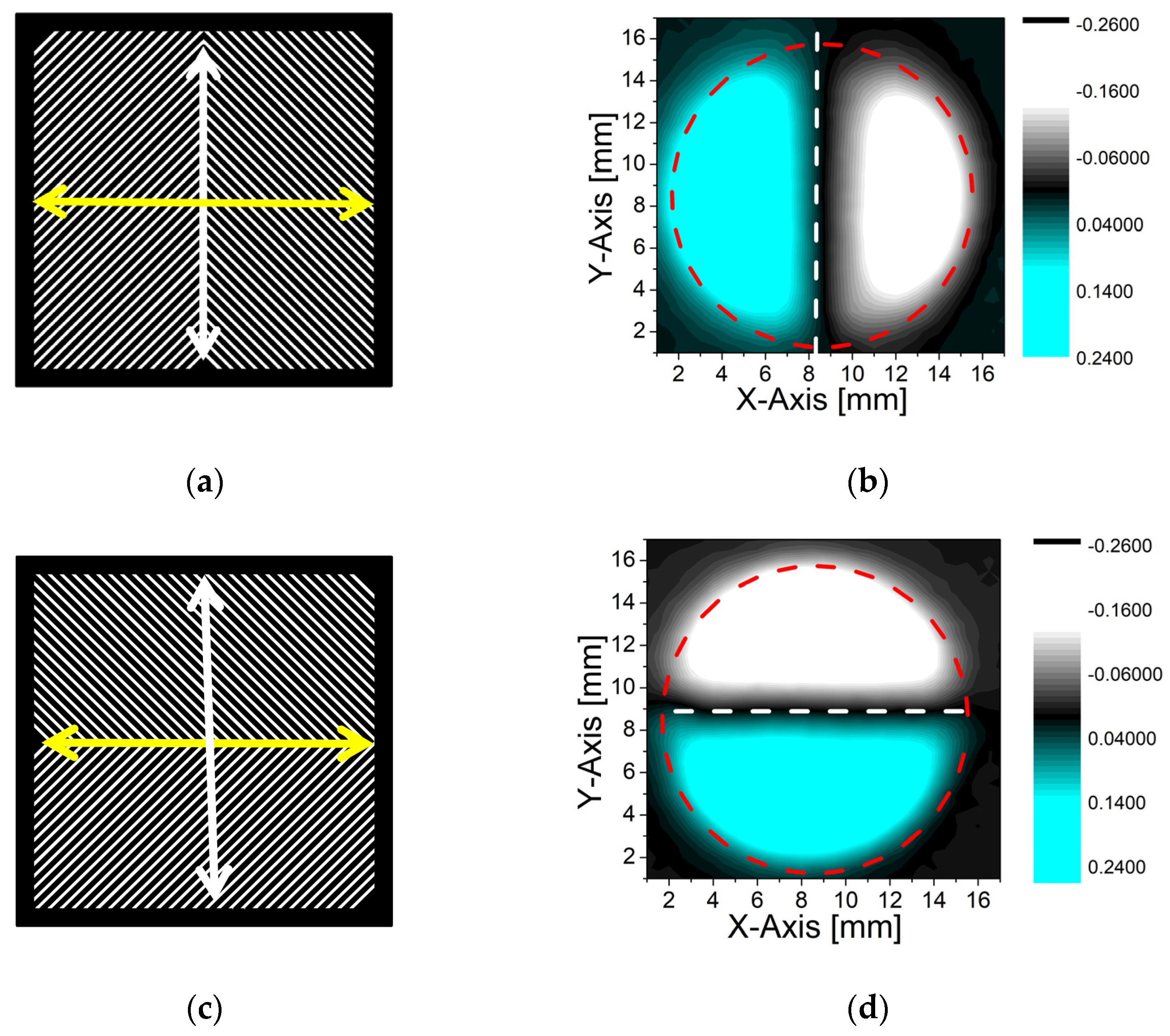
In such a way, it is possible to create a large surface, quasi-ideal phase retardation in between the two sides of the device. This allows not only to control the directivity (right-handed and/or left-handed) of the electromagnetic field polarization direction but also to have the flexibility to select the plane of symmetry around the central axes of choice (x and/or y), by simply rotating the device by 90° with respect to the impinging beam polarization orientation, as shown in
Figure 3a–d.
As the photoconductive detector is sensitive to the electric field in one linear polarization direction, it allows monitoring of both the intensity and phase changes from the general shape of the time domain signal (see
Figure 1c). This approach has been previously applied in different works to reconstruct the spatial distribution of a THz beam and depict the E-Field intensity and the related phase changes [
12,
22]. Analogously, we have mapped the peak position of the THz waveforms as shown in
Figure 3. The images show how the electromagnetic field is being manipulated by using the phase shifter plate. As it is clearly seen from the E-field maps, the polarization state of the THz transient makes a 180° phase shift in between the two gradients of the phase plate.
As shown in
Figure 3a, the left side wave plate component of the device makes a 45
° rotation w.r.t. the polarization direction (PD) of the impinging beam. When the device is rotated 90° w.r.t. PD, the right-side wave plate component (making a 135° rotation w.r.t. PD) relocates itself creating the geometry at the bottom side component and constructing a 45° rotation angle w.r.t. PD (
Figure 3c). With the same analogy, the right-side component (135° rotation w.r.t. PD) shown in
Figure 3a relocates to the top section of the device (
Figure 3c) creating an impinging angle of 135° w.r.t. PD. This way the beam axial symmetry converts from perpendicular to horizontal configuration under 90
° clockwise rotation, giving the flexibility to select the plane of symmetry around the chosen central axes of choice. Due to the scattering and super imposition effects at the intersection of the two wave plate sections, the beam is slightly distorted as seen from the E-field maps shown in
Figure 3b,d. It is worth mentioning that this design can be also applied to more complex production methodologies, such as using intrinsically birefringent media, liquid crystal-based platforms, and/or using higher resolution printing techniques. Moreover, in FEL applications, where signal emission may cover frequencies in the orders of tens of THz, the groove structures and sizes of the device are being scaled down to micro size levels, reducing the side effects mentioned above.


