Communication

Experimental Generation of Structured Light Beams through Highly Anisotropic Scattering Media with an Intensity Transmission Matrix Measurement

Shandong Provincial Engineering and Technical Center of Light Manipulations & Shandong Provincial Key Laboratory of Optics and Photonic Device, School of Physics and Electronics, Shandong Normal University, Jinan 250358, China
*
Author to whom correspondence should be addressed.
Photonics 2023, 10(7), 737; https://doi.org/10.3390/photonics10070737
Submission received: 2 June 2023 / Revised: 21 June 2023 / Accepted: 26 June 2023 / Published: 27 June 2023
(This article belongs to the Special Issue Technologies and Applications of Biophotonics)

Abstract

:
Structured light beams have played important roles in the fields of optical imaging and optical manipulation. However, light fields scatter when they encounter highly anisotropic scattering media, such as biological tissue, which destroys their original structured fields and turns them into speckle fields. To reconstruct structured light beams through highly anisotropic scattering media, we present a method based on intensity transmission matrix which only relates the input and output light intensity distributions. Compared with the conventional method which relies on the measurement of complex-valued transmission matrix, our scheme is easy to implement, fast and stable. With the assistance of spatial filters, three kinds of structured light beams, Bessel-like beams, vortex beams and cylindrical vector beams, were constructed experimentally through a ZnO scattering layer. The present method is expected to promote optical applications through highly anisotropic scattering media.

1. Introduction

The structured light beams with particular spatial distributions have been widely used in many fields, such as optical manipulation [1,2,3] and optical imaging [4,5]. For example, non-diffracting beams, such as Bessel beam, are a typical representative of the new structured light beams, which are expected to increase the penetration depth of beams in biological tissues [6] and have been used for simultaneous micromanipulation in multiple planes due to their self-healing abilities and their abilities to propagate in a long distance [1]. Vortex beam is another type of structured light beams and possesses helical structure and singularities in its phase distribution, which has shown its outstanding performance in rotating particles as optical spanner [2] and in increasing capacity for optical communication [7]. In contrast to scalar beams, vector beams have structured distributions in their polarization distributions. As a typical vector beam, cylindrical vector beam has a cylindrical polarization and has attracted much attention in several fields, such as super-resolution imaging [8], optical manipulation [3,9] and laser materials processing [10]. These studies mentioned above are usually carried out in free space.
However, propagation of structured light could meet highly anisotropic scattering environment, such as thick biological tissues, strong atmosphere, and multimode fiber, where multiple scattering will completely scramble the phase, amplitude and polarization structure of the incident light [11,12,13,14]. Thus, the output field ultimately turns out to be speckle pattern. As a result, the performance of the structured light is highly prohibited, which prevents the optical applications, such as optical manipulation and optical imaging through highly anisotropic scattering media (HASM). Fortunately, wavefront shaping techniques, such as the transmission matrix [15,16,17] (TM) method, digital optical phase conjugation [18] (DOPC) and iterative optimization schemes [19,20,21,22] have opened up the possibility to deal with scattering and reconstruct structured light beams through HASM. Xie et al. have calibrated the complex vector transmission matrix (VTM) of a HASM and realized focusing a vector beam through the HASM using the measured VTM [23]. Yu et al. showed that the structured beams, such as Bessel beams and vector vortex beams can be shaped through the HASM using the VTM method [24]. Diego Di Battista et al. generated Bessel-like beam behind the scattering media by using a spatial filter with a phase scan algorithm [25]. Antoine Boniface and his colleagues presented a TM-based operator which is built by numerically applying a well-chosen mask in a virtual Fourier plane of the output modes of the experimentally measured TM [26]. By performing digital optical phase conjugation on this operator, one can produce the focus with desired point spread function (PSF) distribution through the multiple scattering media. With the help of a radial polarization converter and a polarizer, we have demonstrated how to construct cylindrical vector beams through HASM with a single scalar TM measurement in our previous work [27].
However, the existing methods of constructing structured light beams through HASM usually requires to measure the complex-valued TM, which represents the transmission coefficients between the segments on the input field and output field. To calibrate the complex-valued TM, the holographic methods are conventionally used, and a reference setup is usually needed, which pose a high demand for stability and accuracy in the process of TM calibration. In addition, the present methods usually rely on complex computations. In order to simplify this process, we present the possibility of establishing structured light beams through HASM using an intensity TM measurement combined with a real filter, which is independent of reference arm and free of complex computations. Compared to the conventional TM calibration based on the four-phase method, our measure times is shortened to half. To verify the fidelity of our scheme, Bessel-like beams, cylindrical vector beams and vortex beams have been constructed through a highly anisotropic scattering layer.

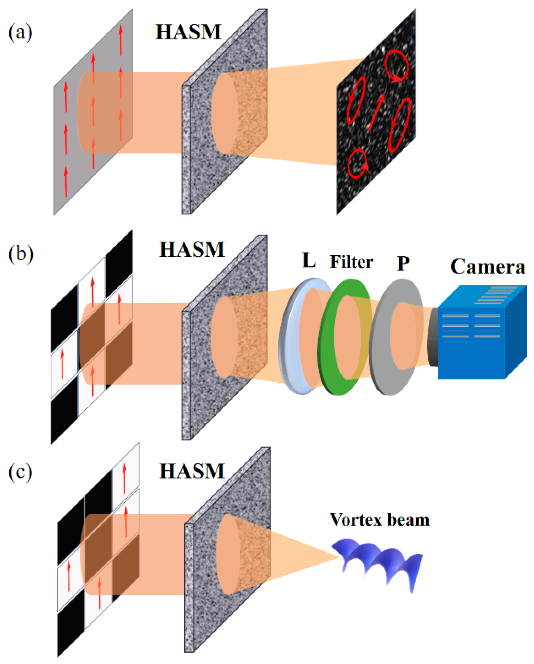
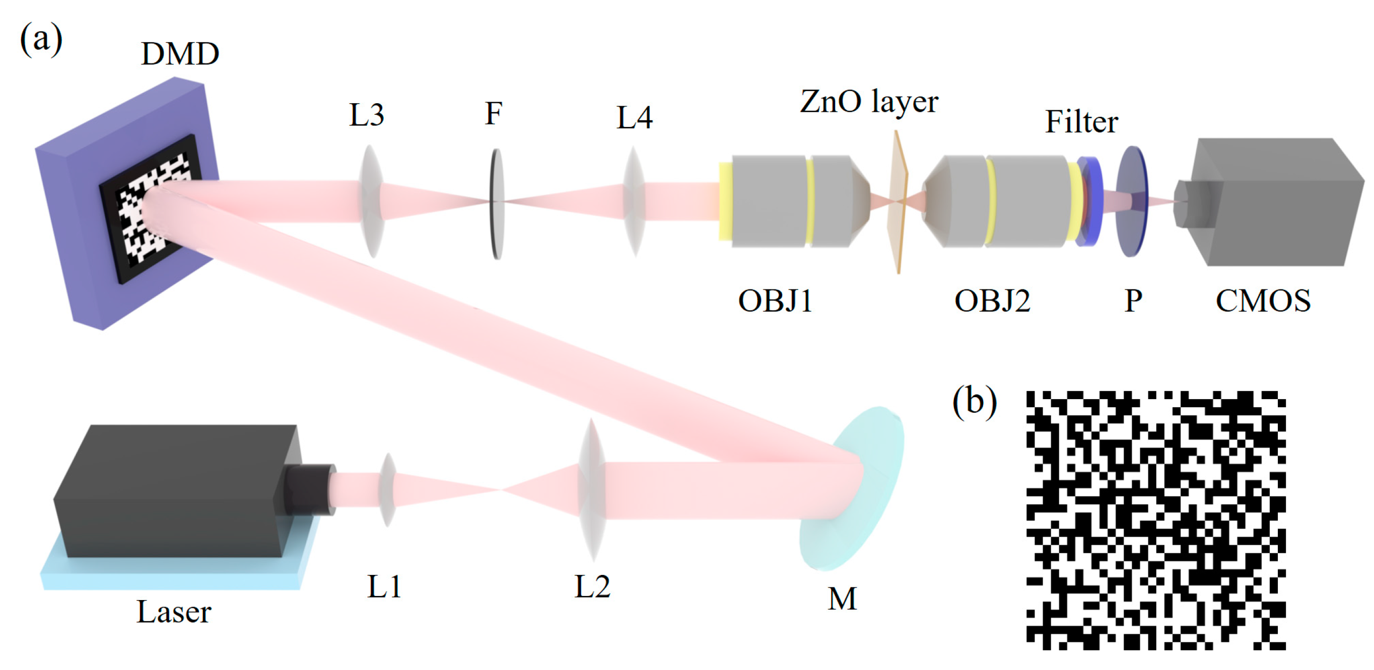
2. Methods and Experimental Scheme

When a linearly polarized beam impinges on a HASM, photons are scattered multiple times in the medium and an intensity speckle field is formed behind the medium. Because of the depolarization effect of the multiple scattering, the intensity speckles possess random polarization states Figure 1a. In the multiple scattering process, light’s degrees of freedom (DOFs), including amplitude, phase and polarization, are couples. In theory, taking advantage of this couple effect, the light beam behind the medium can be designed by shaping some DOFs of incident field.
To construct the desired structured light beams at the output plane, a TM-based operator has been presented which is built by numerically applying a special filter mask in a virtual Fourier plane of the output modes of the experimentally measured TM [26]. This operation is equivalent to engineer the PSF of the scattering system. Instead, a real mask can be put on the Fourier plane of the output plane to filter the TM in the process of TM calibration, then a conjugated wavefront can be calculated by taking the optical conjugation of the filtered TM, and finally the desired PSF distribution can be shaped through the HASM with the filter mask removed. The key of wavefront shaping through HASM in this process is to compensate the scattering effect and calculate a conjugated wavefront for focusing at a specific location at the output plane. Conventionally, to achieve this goal, the complex-valued TM which links the input and output light fields of the HASM is calibrated, and used to calculate the optimized wavefront for shaping a bright focus through HASM. However, its calibration relies on complicated experimental setup and complex computations. Compared to complex-valued TM, the intensity transmission matrix which connects the input and output light intensity distributions has recently been employed to recover the image from the intensity speckle through scattering media, and form the focal spot behind scattering media [28,29].
Here, to engineer the PSF of the scattering system, a real filter is put at the exit pupil plane of the imaging lens to filter the Fourier field of the output plane, as shown in Figure 1b. In order to achieve a fast wavefront shaping through the scattering system, the real-valued intensity transmission matrix (RVITM) method is used [29]. In the process of wavefront shaping, the number of input modes and output modes are set as N and M, respectively. In the calibration process, each column of a binary matrix [H1, H2] is reshaped to be a square matrix as a binary amplitude input wavefront, where H1 = (H + 1)/2 and H2 = (−H + 1)/2; H is a Hadamard matrix ∈ (−1, +1) and has a dimension of N × N. With the 2N binary Hadamard patterns impinged on the HASM in sequence, the RVITM can be written as,
R V I T M = [ 2 I 1 1 I 1 1 2 I 1 p I 1 1 2 I m 1 I 1 1 2 I m p I 1 1 ] [ H , H ] T
where, I m p is the intensity value at the mth mode in the pth output speckle pattern.
To establish a focus at the output plane whose intensity distribution is denoted as Iout, an optimized input intensity mask is obtained by,
I i n = R V I T M + I o u t .
Further, a binary process is used to obtain the binary intensity input:
I i n _ b i n a r y = { 1 , I i n > 0 0 , I i n < 0 .
At last, the optimized binary amplitude input field is produced by a spatial light modulator to construct the structured light beam (such as a vortex beam) through HASM, as shown in Figure 1c.
The experimental scheme is illustrated in Figure 2. To achieve a fast TM calibration, we used a high-speed digital micro-mirror device (DMD, V-7001, Vialux, Chemnitz, Germany) as the spatial light modulator. A laser beam (Cobolt 04-01 series) with a wavelength of 532 nm transports through a beam expander consisting of L1 and L2 and then is reflected by a mirror M to fully illuminate the surface of the DMD. With the help of a 4f configuration and a spatial filter, DMD enables to shape binary amplitude of the light in its zeroth-diffraction-order beam [30,31]. A binary amplitude mask loaded on DMD is presented in Figure 2b. The modulated beam passes through the first objective OBJ1 (10×, NA = 0.25) and impinges on a ZnO scattering layer with a thickness of ~200 μm. The transmitted light field is then collected with the second objective OBJ2 (60×, NA = 0.85) and imaged using a CMOS camera (D752, PixeLINK, Ottawa, Canada). Note that the distance between the ZnO scattering layer and the focal plane is about 200 μm. To engineer the PSF distribution of the system, a filter is placed at the exit pupil of the OBJ2. A polarizer is adopted to select one polarization state of the output field. In the experiment, N = 32 × 32 segments on DMD and M = 480 × 480 pixels on CMOS cameras are used as input and output modes, respectively.

3. Experimental Results

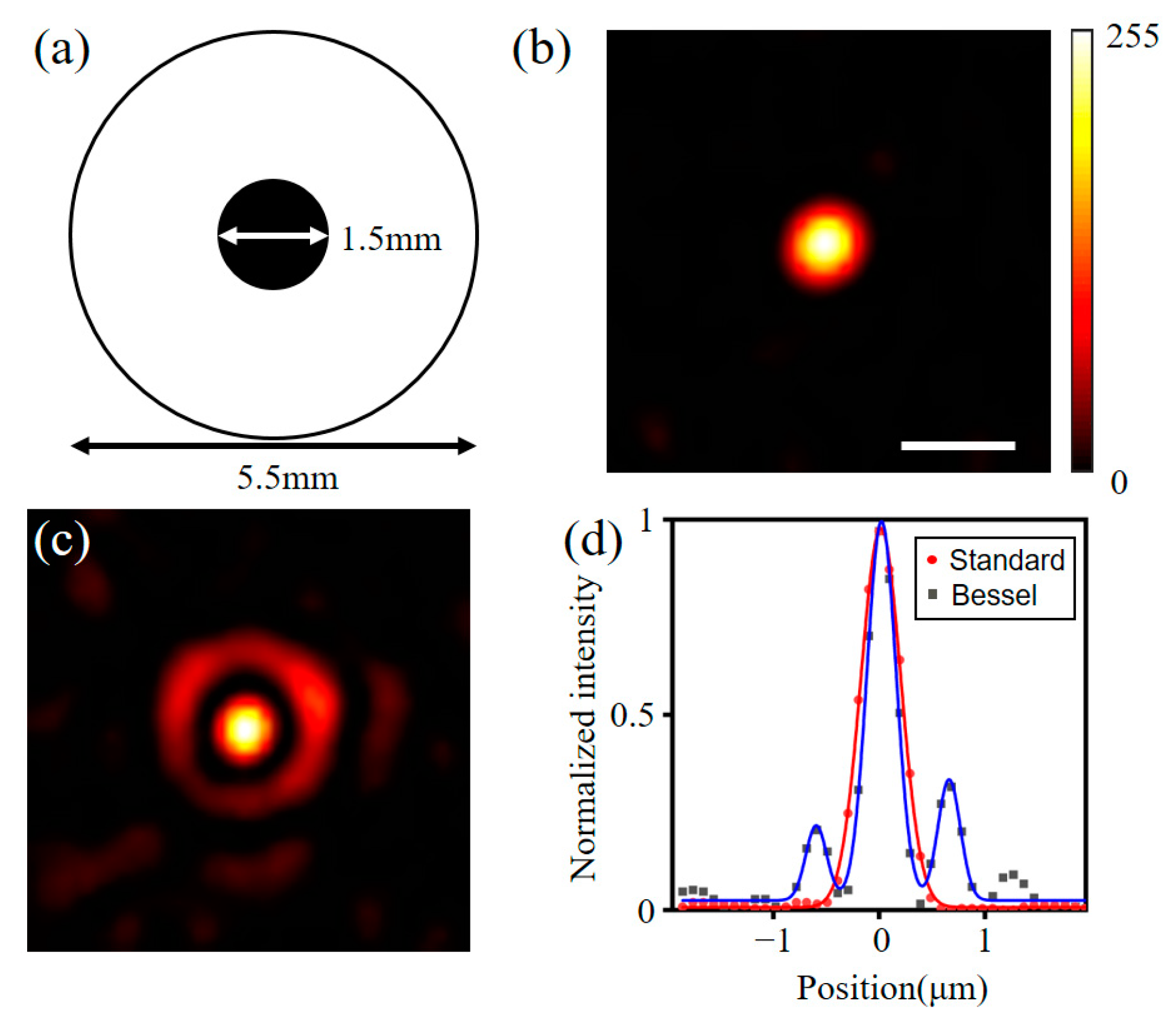
3.1. Construct Bessel-like Beams through ZnO Scattering Layer

To verify the fidelity of the method, we first experimentally constructed a Bessel-like beam through the ZnO scattering layer. In order to construct a Bessel-like beam, an annular pattern was used as a binary amplitude filter, which is shown in Figure 3a. There is a black obstacle in the center of the filter, while the other region is transparent. The inner diameter and outer diameter of the filter are 5.5 mm and 1.5 mm, respectively. With the annular filter placed at the Fourier plane of the output plane, the corresponding RVITM was measured. After that, the binary optimized input amplitude mask was calculated and loaded on the DMD. With the incident of the optimized binary amplitude wavefront, we compensated the scattering effect and achieved focusing at the center of the output plane, as shown in Figure 3b. Then, we removed the filter and observed the light distribution at the output plane, which is shown in Figure 3c. As we can see, there is a Bessel-like distribution. In order to compare the beam size, the cross-sectional intensity distributions of this beam and a standard beam generated without engineering the PSF are, respectively presented as the blue and red lines, shown in Figure 3d. To compare the focus size of the two beams, the full width at half maximum (FWHM) of the standard beam and Bessel-like beam were measured, which are 0.38 μm and 0.27 μm, respectively. In this case, the central lobe FWHM of this Bessel-like beam is 29% narrower than the standard beam.

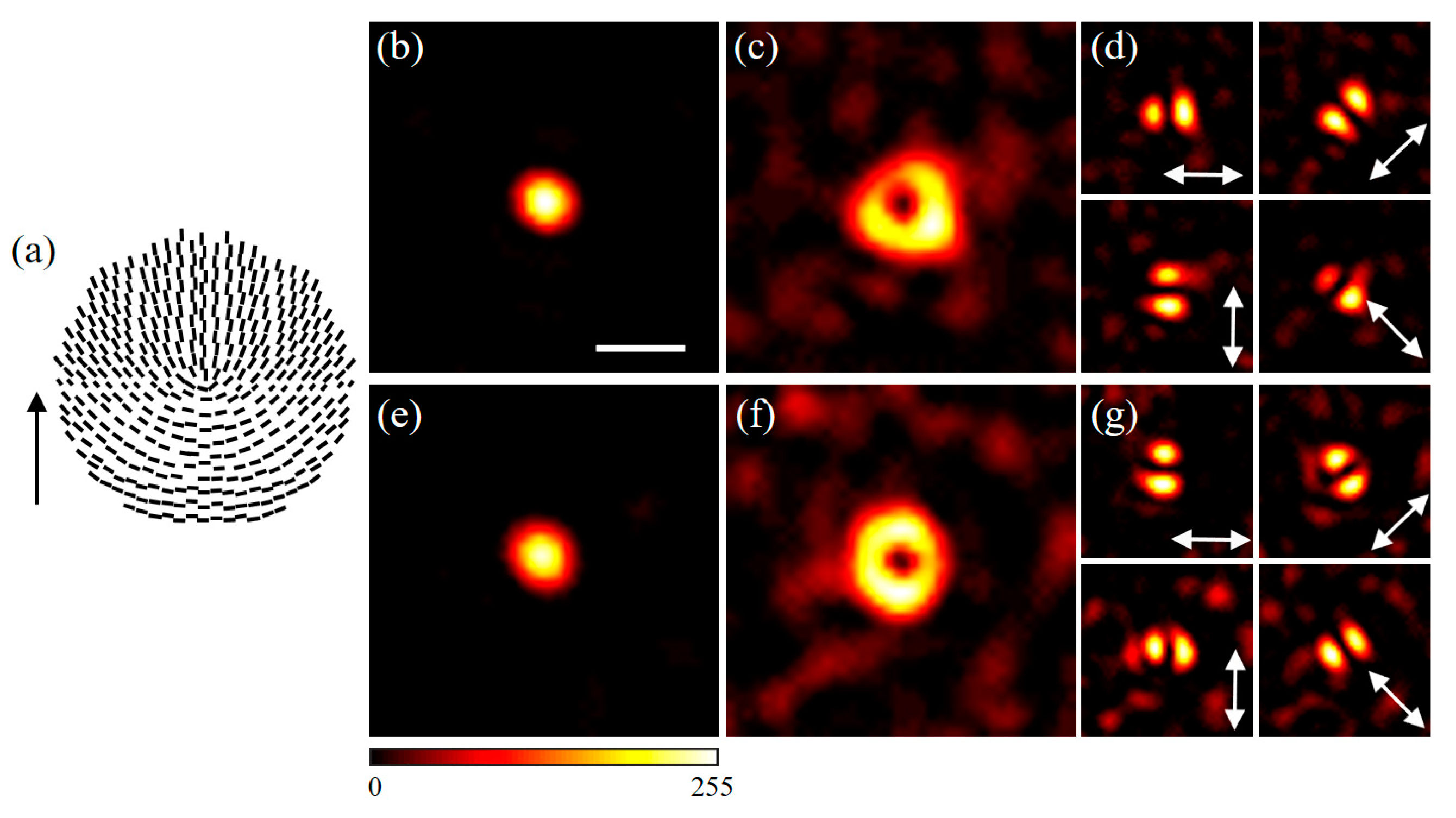
3.2. Construct Radially and Azimuthally Polarized Beams through ZnO Scattering Layer

Apart from constructing the Bessel-like beams, we also explored the construction of cylindrical vector beams through the ZnO scattering layer. To generate radially and azimuthally polarized beams, an S-waveplate (RPC-532-06, Altechna R&D, Vilnius, Lithuania) and a polarizer were used in the process of wavefront shaping. S-waveplate was employed to be a spatial polarization filter of the output field whose surface is filled with spatially variant subwavelength gratings fabricated by a femtosecond laser pulse. These grating structures perform as many half-wave plates and their directions are shown in Figure 4a. The direction of the black arrow indicates the orientation of S-waveplate. According to our previous published paper [27], the radial polarized beam could be produced through HASM when the orientation of S-waveplate is aligned parallel to the transmission axis of the polarizer in the process of wavefront shaping. In comparison, the case of producing azimuthally polarized beam requires that the orientation of the S-waveplate is perpendicular to the transmission axis of the polarizer.
To construct the radially polarized beam, the RVITM of the scattering system with the orientation of the S-waveplate parallel to the transmission axis of the polarizer was measured first. Then, with the optimized binary amplitude input field impinging on the ZnO scattering layer, a tight focus was shaped at the output plane Figure 4b. In order to detect the light distribution behind the ZnO scattering layer, the S-waveplate and the polarizer were removed. Then, a donut intensity pattern appeared and its intensity pattern is shown in Figure 4c. To examine the polarization property of the donut beam, an analyzer was placed in front of the CMOS camera. The transmission axis of the analyzer was, respectively changed by 0°, 45°, 90° and 135°, and the detected intensity patterns are presented in Figure 4d, from which we can see that the donut beam possesses a radially polarized distribution. In the same way, an azimuthally polarized beam was generated through the ZnO scattering layer, and the corresponding experimental results are, respectively shown in Figure 4e–g. Note that a generalized cylindrical beam can be constructed by setting an appropriate angle between the orientation of the S-waveplate and the transmission axis of the polarizer.

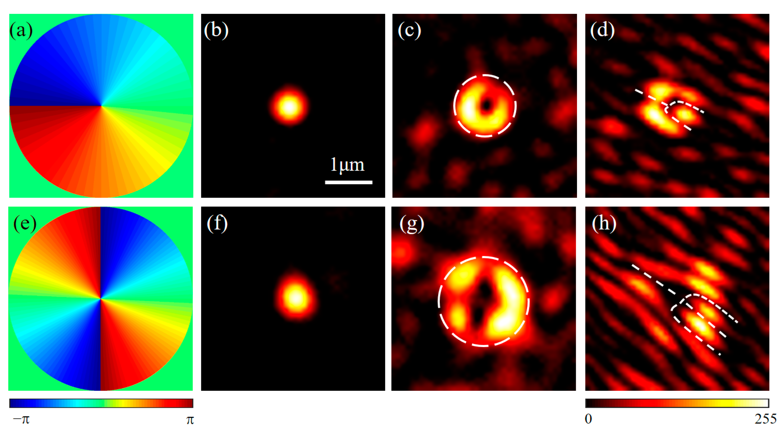
3.3. Construct Vortex Beams through ZnO Scattering Layer

To construct vortex beams, two vortex phase plates (LCT106-220418, m = 1 and LCT114-220624, m = 2; m is topological number, LBTEK, Changsha, China) were employed to be spatial phase filters. The phase distribution of the first vortex phase plates is presented in Figure 5a. The intensity of the focus after implementing the wavefront shaping is presented in Figure 5b. With the vortex phase plate removed, the light distribution behind the ZnO scattering layer appeared and was a donut beam, whose intensity pattern is shown in Figure 5c. To detect its phase structure, one plane beam was used to interfere with this donut beam in an off-axis geometry. The interference intensity field is shown in Figure 5d. As we can see, interference field includes many stripes that look like branches. The number of the branches can be counted from the pattern and is equal to 1, which indicates that the corresponding topological charge of the beam is 1. Moreover, the corresponding phase distribution and experimental results for using the second vortex phase plate as a filter are shown in Figure 5e–h. As we can see, the vortex beam with topological charge of 2 was established through the ZnO scattering layer by employing the second vortex phase plate as a spatial phase filter.

4. Discussion

High scattering makes it an obstacle to demonstrate the performance of structured light beams through HASM. It is of vital importance to construct structured light beams beyond high scattering for the fields, such as optical imaging and optical manipulation through highly anisotropic scattering environment. The key to generating structured light beams through HASM is to find the conjugated wavefront for focusing at a specific location of the output plane. In ref. [26], the conjugated wavefront is computed by taking optical phase conjugation of the filtered TM, which is calculated by filtering the calibrated TM with a digital filter. In this case, this method requires complex calculations. To address this problem, we propose that the conjugated wavefront can be directly obtained by the measured intensity TM, which is filtered via a real filter mask positioned in the light path. In this way, the advantage of our proposed method is that it avoids complicated calculations in the process of constructing structured light beams through HASM. Furthermore, the wavefront shaping technology used in this method only relies on the binary amplitude modulation, which is independent of the complex amplitude modulated algorithms. In addition to the advantage of simple computation, the modulated beam is in the zeroth-diffraction-order beam, which is more efficient than the case of the first-diffraction-order beam. The advantage of the former method is that different filters can be generated digitally with high flexibility. In comparison, the generation and conversion of the real filters in our proposed method cannot be easily implemented as the digital filter. Luckily, a filter shaped by a programmable spatial light modulator can make the generation conveniently.
In the process of wavefront shaping through HASM, the input plane is divided into N input modes. For the TM calibration based on the four-phase method, it requires to capture 4N intensity speckle patterns to derive the TM. However, the number of required patterns in this proposed method is just 2N, which is a half than the four-phase method. In theory, the intensity TM loses the phase information compared to complex-valued TM, thus, structured light beams are generated through HASM with a higher speckle background than the complex-valued TM. Fortunately, increasing the resolution of the input field, i.e., the number of input modes N, could help to improve the signal-to-noise ratio of the generated structured light beams [32].

5. Conclusions

In summary, we have experimentally constructed structured light beams, such as Bessel-like beams, cylindrical vector beams and vortex beams through HASM with an intensity transmission matrix calibration in combination with a spatial filter. Contrast to the method of measuring complex-valued TM, this method only relies on the detection of the intensity of the output field, which has the advantage of high-speed and convenience in terms of optical implementation. The proposed method is expected to promote the applications of structured light beam through highly anisotropic scattering environment. This method can also be extended to the other complex media, such as multimode fiber.

Author Contributions

Conceptualization, Q.Z. and Q.L.; methodology, S.T.; software, H.G.; validation, Q.Z., Q.L. and S.T.; investigation, Q.L.; data curation, Q.L.; writing—original draft preparation, Q.L.; writing—review and editing, Q.Z. and Q.L.; supervision, Q.Z. and Y.C.; project administration, Q.Z. and Y.C.; funding acquisition, Q.Z. and Y.C. All authors have read and agreed to the published version of the manuscript.

Funding

This research was funded by the National Key Research and Development Program of China (No. 2019YFA0705000), the National Natural Science Foundation of China (NSFC) (Nos. 12004219, 12192254, 91750201 and 11974218), the Innovation Group of Jinan (No. 2018GXRC010), and the Local Science and Technology Development Project of the Central Government (No. YDZX20203700001766).

Institutional Review Board Statement

Not applicable.

Informed Consent Statement

Not applicable.

Data Availability Statement

Not applicable.

Conflicts of Interest

The authors declare no conflict of interest.

References

  1. Garcés-Chávez, V.; McGloin, D.; Melville, H.; Sibbett, W.; Dholakia, K. Simultaneous micromanipulation in multiple planes using a self-reconstructing light beam. Nature 2002, 419, 145–147. [Google Scholar] [CrossRef] [PubMed]
  2. Padgett, M.; Bowman, R. Tweezers with a twist. Nat. Photonics 2011, 5, 343–348. [Google Scholar] [CrossRef]
  3. Zhan, Q. Trapping metallic Rayleigh particles with radial polarization. Opt. Express 2004, 12, 3377–3382. [Google Scholar] [CrossRef]
  4. Fahrbach, F.O.; Simon, P.; Rohrbach, A. Microscopy with self-reconstructing beams. Nat. Photonics 2010, 4, 780–785. [Google Scholar] [CrossRef]
  5. Yu, W.; Ji, Z.; Dong, D.; Yang, X.; Xiao, Y.; Gong, Q.; Xi, P.; Shi, K. Super-resolution deep imaging with hollow Bessel beam STED microscopy. Laser Photonics Rev. 2016, 10, 147–152. [Google Scholar] [CrossRef] [Green Version]
  6. Gohn-Kreuz, C.; Rohrbach, A. Light needles in scattering media using self-reconstructing beams and the STED principle. Optica 2017, 4, 1134. [Google Scholar] [CrossRef]
  7. Wang, J.; Yang, J.-Y.; Fazal, I.M.; Ahmed, N.; Yan, Y.; Huang, H.; Ren, Y.; Yue, Y.; Dolinar, S.; Tur, M. Terabit free-space data transmission employing orbital angular momentum multiplexing. Nat. Photonics 2012, 6, 488. [Google Scholar] [CrossRef]
  8. Xue, Y.; Kuang, C.; Li, S.; Gu, Z.; Liu, X. Sharper fluorescent super-resolution spot generated by azimuthally polarized beam in STED microscopy. Opt. Express 2012, 20, 17653–17666. [Google Scholar] [CrossRef]
  9. Zhong, M.-C.; Gong, L.; Li, D.; Zhou, J.-H.; Wang, Z.-Q.; Li, Y.-M. Optical trapping of core-shell magnetic microparticles by cylindrical vector beams. Appl. Phys. Lett. 2014, 105, 181112. [Google Scholar] [CrossRef]
  10. Meier, M.; Romano, V.; Feurer, T. Material processing with pulsed radially and azimuthally polarized laser radiation. Appl. Phys. A 2007, 86, 329–334. [Google Scholar] [CrossRef] [Green Version]
  11. de Aguiar, H.B.; Gigan, S.; Brasselet, S. Polarization recovery through scattering media. Sci. Adv. 2017, 3, e1600743. [Google Scholar] [CrossRef] [Green Version]
  12. Mosk, A.P.; Lagendijk, A.; Lerosey, G.; Fink, M. Controlling waves in space and time for imaging and focusing in complex media. Nat. Photonics 2012, 6, 283–292. [Google Scholar] [CrossRef] [Green Version]
  13. Vellekoop, I.M.; Lagendijk, A.; Mosk, A.P. Exploiting disorder for perfect focusing. Nat. Photonics 2010, 4, 320–322. [Google Scholar] [CrossRef] [Green Version]
  14. Han, T.; Peng, T.; Li, R.; Wang, K.; Sun, D.; Yao, B. Extending the Imaging Depth of Field through Scattering Media by Wavefront Shaping of Non-Diffraction Beams. Photonics 2023, 10, 497. [Google Scholar] [CrossRef]
  15. Andreoli, D.; Volpe, G.; Popoff, S.; Katz, O.; Gresillon, S.; Gigan, S. Deterministic control of broadband light through a multiply scattering medium via the multispectral transmission matrix. Sci. Rep. 2015, 5, 10347. [Google Scholar] [CrossRef] [Green Version]
  16. Popoff, S.M.; Lerosey, G.; Carminati, R.; Fink, M.; Boccara, A.C.; Gigan, S. Measuring the transmission matrix in optics: An approach to the study and control of light propagation in disordered media. Phys. Rev. Lett. 2010, 104, 100601. [Google Scholar] [CrossRef]
  17. Tripathi, S.; Paxman, R.; Bifano, T.; Toussaint, K.C., Jr. Vector transmission matrix for the polarization behavior of light propagation in highly scattering media. Opt. Express 2012, 20, 16067–16076. [Google Scholar] [CrossRef] [Green Version]
  18. Wang, D.; Zhou, E.H.; Brake, J.; Ruan, H.; Jang, M.; Yang, C. Focusing through dynamic tissue with millisecond digital optical phase conjugation. Optica 2015, 2, 728–735. [Google Scholar] [CrossRef] [Green Version]
  19. Li, H.; Woo, C.M.; Zhong, T.; Yu, Z.; Luo, Y.; Zheng, Y.; Yang, X.; Hui, H.; Lai, P. Adaptive optical focusing through perturbed scattering media with a dynamic mutation algorithm. Photonics Res. 2021, 9, 202–212. [Google Scholar] [CrossRef]
  20. Vellekoop, I.M. Feedback-based wavefront shaping. Opt. Express 2015, 23, 12189–12206. [Google Scholar] [CrossRef]
  21. Conkey, D.B.; Brown, A.N.; Caravaca-Aguirre, A.M.; Piestun, R. Genetic algorithm optimization for focusing through turbid media in noisy environments. Opt. Express 2012, 20, 4840–4849. [Google Scholar] [CrossRef]
  22. Li, R.; Peng, T.; Liang, Y.; Yang, Y.; Yao, B.; Yu, X.; Min, J.; Lei, M.; Yan, S.; Zhang, C.; et al. Interleaved segment correction achieves higher improvement factors in using genetic algorithm to optimize light focusing through scattering media. J. Opt. 2017, 19, 105602. [Google Scholar] [CrossRef] [PubMed]
  23. Xie, Y.-Y.; Wang, B.-Y.; Cheng, Z.-J.; Yue, Q.-Y.; Guo, C.-S. Measurement of vector transmission matrix and control of beam focusing through a multiple-scattering medium based on a vector spatial light modulator and two-channel polarization holography. Appl. Phys. Lett. 2017, 110, 221105. [Google Scholar] [CrossRef]
  24. Yu, P.; Zhao, Q.; Hu, X.; Li, Y.; Gong, L. Tailoring arbitrary polarization states of light through scattering media. Appl. Phys. Lett. 2018, 113, 121102. [Google Scholar] [CrossRef]
  25. Di Battista, D.; Zacharakis, G.; Leonetti, M. Enhanced adaptive focusing through semi-transparent media. Sci. Rep. 2015, 5, 17406. [Google Scholar] [CrossRef] [PubMed] [Green Version]
  26. Boniface, A.; Mounaix, M.; Blochet, B.; Piestun, R.; Gigan, S. Transmission-matrix-based point-spread-function engineering through a complex medium. Optica 2017, 4, 54. [Google Scholar] [CrossRef] [Green Version]
  27. Zhao, Q.; Tu, S.; Lei, Q.; Guo, C.; Zhan, Q.; Cai, Y. Creation of cylindrical vector beams through highly anisotropic scattering media with a single scalar transmission matrix calibration. Photonics Res. 2022, 10, 1617–1623. [Google Scholar] [CrossRef]
  28. Liu, K.; Zhang, H.; Du, S.; Liu, Z.; Zhang, B.; Fu, X.; Liu, Q. Particle manipulation behind a turbid medium based on the intensity transmission matrix. Photonics Res. 2022, 10, 2293–2301. [Google Scholar] [CrossRef]
  29. Zhao, T.; Ourselin, S.; Vercauteren, T.; Xia, W. Seeing through multimode fibers with real-valued intensity transmission matrices. Opt. Express 2020, 28, 20978–20991. [Google Scholar] [CrossRef]
  30. Woo, C.M.; Zhao, Q.; Zhong, T.; Li, H.; Yu, Z.; Lai, P. Optimal efficiency of focusing diffused light through scattering media with iterative wavefront shaping. APL Photonics 2022, 7, 046109. [Google Scholar] [CrossRef]
  31. Zhao, Q.; Wang, Z.-Q.; Yu, P.-P.; Li, Y.-M.; Gong, L. Vector focusing through highly scattering media via binary amplitude modulation. Appl. Phys. Express 2019, 12, 062002. [Google Scholar] [CrossRef]
  32. Vellekoop, I.M.; Mosk, A. Focusing coherent light through opaque strongly scattering media. Opt. Lett. 2007, 32, 2309–2311. [Google Scholar] [CrossRef]
Figure 1. Illustration of generating structured light beam through HASM with binary amplitude modulation. (a) The incident beam with linear polarization is scrambled to be intensity speckle with random polarization distribution. (b) Principal schematic of RVITM calibration to construct structured light beams through HASM with a real filter filtering the Fourier field of the output plane. L, lens; P: polarizer. (c) Construction of a structured light beam (for example, a vortex beam) through HASM by impinging an optimized binary amplitude wavefront.
Photonics 10 00737 g001
Figure 2. Experimental scheme. (a) Experimental setup. L, lens; M, mirror; DMD, digital micro-mirror device; F, filter; OBJ, objective lens; P, polarizer; CMOS, complementary metal-oxide-semiconductor camera. (b) A binary amplitude mask loaded on the DMD.
Photonics 10 00737 g002
Figure 3. Construct a Bessel beam through the ZnO scattering layer. (a) The annular binary filter. (b) Intensity pattern of the focus at the plane of CMOS camera with the incident of the optimized binary amplitude wavefront. (c) Observed intensity distribution of a Bessel-like beam with the filter removed. (d) The cross-sectional intensity profiles for standard beam (red line) and Bessel-like beam (blue line). Scale bar, 1 μm.
Photonics 10 00737 g003
Figure 4. Construction of radially polarized and azimuthally polarized beams through the ZnO scattering layer. (a) The schematic of the nanogratings’ orientation on the surface of S-waveplate. (b) Intensity profile of the focus at the plane of CMOS camera when the S-waveplate and polarizer remain in the optical path. (c) Observed donut intensity profile with the S-waveplate and the polarizer removed. (d) Fields behind a polarizer whose orientation of transmission axis (represented by the white arrows) is 0°, 45°, 90°, and 135°, respectively. (eg) Corresponding results for creating an azimuthally polarized beam through the ZnO scattering layer. Scale bar, 1 μm.
Photonics 10 00737 g004
Figure 5. Construct vortex beams through the ZnO scattering layer. (a) The phase distribution of the vortex phase plate, m = 1; m is the topological charge. (b) Intensity profile of the focus at the plane of CMOS camera when the process of wavefront shaping was implemented. (c) Observed intensity distribution of a vortex beam with the vortex half-wave plate and the polarizer removed. A circle formed by white dashed line is used to indicate the boundary of the donut beam. (d) Interference patterns between the vortex beam and a plane wave. The interference field includes many stripes that look like branches, whose directions are indicated by the white dashed lines. (eh) Corresponding results for creating vortex beam with topological charge of 2 through the ZnO scattering layer. Scale bar, 1 μm.
Photonics 10 00737 g005
Disclaimer/Publisher’s Note: The statements, opinions and data contained in all publications are solely those of the individual author(s) and contributor(s) and not of MDPI and/or the editor(s). MDPI and/or the editor(s) disclaim responsibility for any injury to people or property resulting from any ideas, methods, instructions or products referred to in the content.

