Communication

A Terahertz Radiation Linear Polarizer Based on Using a Magnetic Fluid in an External Magnetic Field

by
Alexey P. Votintsev
1,
Alexey V. Borisov
1,
Zakhar S. Kochnev
1,
Igor Meglinski
2,3 and
Yury V. Kistenev
1,4,*
1
Laboratory of Biophotonics, National Research Tomsk State University, Tomsk 634050, Russia
2
Information Technology and Electrical Engineering, University of Oulu, 900014 Oulu, Finland
3
College of Engineering and Physical Sciences, Aston University, Birmingham B4 7ET, UK
4
V.E. Zuev Institute of Atmospheric Optics SB RAS, Tomsk 634055, Russia
*
Author to whom correspondence should be addressed.
Photonics 2023, 10(6), 675; https://doi.org/10.3390/photonics10060675
Submission received: 1 May 2023 / Revised: 7 June 2023 / Accepted: 9 June 2023 / Published: 11 June 2023
(This article belongs to the Special Issue Polarization Optics in Biomedical Applications)

Abstract

:
A model of a magnetically controlled linear polarizer of terahertz (THz) waves based on a cell filled with a magnetic fluid and controlled by an external magnetic field was proposed. The magnetic fluid consisted of a synthetic oil with high transparency in the THz range and ferromagnetic alloy microparticles. Selection of the ferromagnetic particles size and concentration, and also parameters of the external magnetic field was conducted. It was shown that when using ferromagnetic particles of 10–35 μm size, a concentration of 10 wt.%, and a magnetic field with induction of 6.7–57.2 mT, the created construction works as a linear polarizer of the THz wave in the ranged from 0.3 to 1.5 THz, with the degree of polarization of the initially non-polarized THz wave transmitted through the cell being at least of 80%.

1. Introduction

THz spectroscopy and imaging are widely used for the investigation of biological samples [1,2,3,4,5,6] and medical research [7,8,9,10], environmental monitoring [11,12,13,14,15,16], chemical analysis [17,18,19], communication [20,21,22,23,24], flaw detection [25,26], security applications (detection of explosives, narcotic drugs or dangerous objects under clothing,) [27,28,29], and paintwork studies [30,31,32]. Changing the polarization of initially non-polarized THz waves is a standard task in THz devices.
Many objects, for example biological tissues, are anisotropic because they contain birefringent structures and the ability to control changes in the polarization of THz waves transmitted through them is vital [33,34]. Moreover, the tissue anisotropy is manifested in the scattering coefficient and in the refractive index. Polarizers allow for the analyzing of changes of a THz wave polarization.
Micro-electromechanical systems (MEMS), plasmon, or sub-wavelength resonance based meta-materials are used for THz radiation polarization control [35,36]. MEMS polarizers use spirals with enantiomeric switching [35]. The deformable spiral can be pressed in or squeezed out using the pressure drop between both sides of a film. The THz radiation polarization changing occurs, depending on the direction of the spiral twist.
Measurement of THz radiation polarization can be also conducted by employing various approaches, for example, using a device mechanical rotation [37] or using active (“smart”) materials, liquid crystals, whose optical properties can be changed by a photo-activation [36], an electric field [35] or an external magnetic field application [38]. Chiral meta-materials on a silicon substrate are used as a polarizer controlled by a photo-activation [36]. Here, the chirality is associated with a texture on a meta-material surface, which does not have mirror symmetry lines. These patterns can be produced by the lithography method. This type of device can be configured to convert linear polarization to elliptical polarization [39]. The crystal quartz also converts the THz radiation polarization. The device developed in [37] consists of a set of plane-parallel plates of crystalline quartz with optical birefringence axes orienteered in the plane of the plate. The developed device operates in a wide frequency range.
A mechanically controlled polarizer of THz radiation can be constructed from composite membranes consisting of structured ferromagnetic nanoparticles, when these form spatial structures in a constant magnetic field during the polymerization of a composite membrane [38]. Polarization changing is achieved due to the tilt of the membrane and the change in the angle of incident radiation. When the sample is located in a perpendicular position between the electric vector of the incident THz wave and the direction of the aligned structures, maximum transmission is achieved. The lowest transmission occurs when the membrane is in the parallel position. The degree of THz radiation polarization can be varied by selecting the magnetic material, the size and concentration of particles, as well as the magnitude of the magnetic field used during the stage of composite membrane production.
Magnetic fluids (MFs) can be used for creating controlled THz polarizers. By varying the size and concentration of magnetic particles (MPs), orientation and magnitude of the external magnetic field, it is possible to create functional THz radiation polarizers with necessary spectral properties [40]. This approach enables the creation of cost-effective polarizers compared to photolithography, MEMS, and other methods. Brief information about the ways of changing THz radiation polarization using controlled polarizers, along with their advantages and disadvantages, are presented in Table 1.
The purpose of this paper was to develop a linear polarizer of THz waves based on a magnetic fluid controlled by an external magnetic field.

2. Materials and Methods

2.1. Magnetic Field Generation

Inductors in the form of Helmholtz coils with an external diameter of 70 mm were used as a source of an external magnetic field with high uniformity, as well as with the ability to control the magnitude and direction of the magnetic induction. The dimensions of the coils, the field strength, the number of turns, the diameter of the wire, and the distance between the coils were calculated beforehand. The body of the electromagnets was developed using a software “Autodesk Fusion 360” and printed on a 3D printer (“Picaso 3D. Designer X Pro”, Moscow, Russia) using plastic “PLA” (“BestFilament”, Novosibirsk, Russia) (Figure 1).
The coils were wound with a PETV-2 winding wire with a diameter of 0.5 mm, by hand, strictly turn-by-turn. PETV-2 is a winding heat–resistant wire with a copper core in enamel insulation based on polyesters. The total number of turns in the coils was 1800. The magnetic field was created by applying the external voltage to the inductors using a laboratory power supply unit (“YIHUA-305D-II”, Guangzhou, China) with digital indication and with the ability to adjust the DC voltage and current: the voltage was varied in the 0–30 V interval, the current was limited by 5 A value. To enhance the magnitude of the magnetic field, a pair of ferromagnetic cores with a diameter of 30 mm and a length of 28 mm was used.
The magnetic field characteristics were measured by a magnetometer (“Aktakom ATE–8702”, Moscow, Russia). The magnetometer enables measurements of magnetic fields created by constant (DC) and alternating (AC) currents. The magnetometer measurement ranges were: DC magnetic field—from 0 to 30,000 G (3000 mT); AC magnetic field—from 0 to 15,000 G (1500 mT). The minimum resolution was 0.1 G/0.01 mT. The developed magnetic system generated a stable external magnetic field with the possibility of increasing the magnetic induction up to 57.2 mT. The area of uniformity of the magnetic field had a characteristic size (the shape of a sphere) with a diameter of ≈11 mm, this value exceeded the diameter of the THz spectrometer beam.

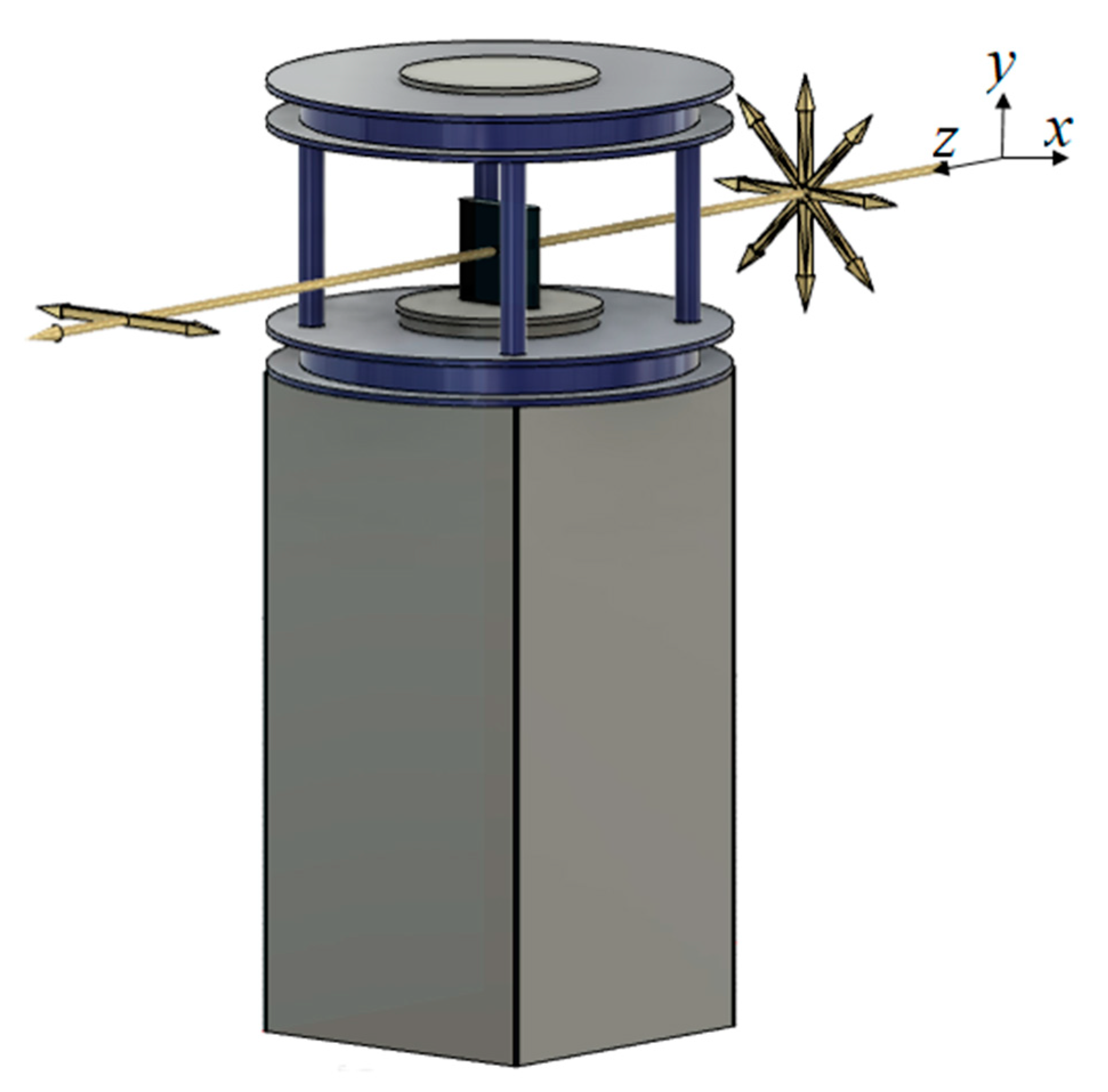
2.2. Design of the Linear Polarizer

Magnetic alloy 5BDSR micro-particles (MPs) of 10–50 μm sizes with concentrations of 2.5, 5 and 10 wt.% were used. Nanocrystalline soft magnetic alloy 5BDSR (FeNbCuMoCoBSi) had a rounded hysteresis loop and had a very high magnetic permeability (μ ≥ 40,000). This material was an analog of the alloys “Finemet” (Hitachi Metals, Tokyo, Japan), “Namglass” (Arnold magnetic technologies, New York, USA), “Vitroperm”(Vacuumschmelze, Hanau, Germany) and was produced at the Ashinsky Metallurgical Plant (Asha Russia) in the form of the thinnest tape [41]. The results of the study of the magnetic properties of these particles were described in detail in [42].
MPs ranging in size from 10 to 50 μm were produced by grinding in a high-energy shredder (“LaarMann. Grinder MG100”, Roermond, the Netherlands), a type of mechanical mortar. The MPs had a characteristic shape of “needles”. A synthetic motor oil “Toyota 5w40” with dynamic viscosity of 0.126 Pa·s and density of 810 kg/m3 having a high transparency in the THz range was chosen as the host fluid [43,44]. The concentration of MPs in a MF was estimated using the formula:
m p = ω m o 100 ω ,
where ω is the required MP concentration (in percent), m o is the mass of the host fluid, m p is the mass of the MPs. Table 2 shows the parameters of the created MF samples.
The MF was injected into a plastic cell printed on a 3D printer using a plastic “Watson” (“BestFilament”, Novosibirsk, Russia). The cell with MF was placed between the Helmholtz coils with a ferromagnetic core.
The photos of the cell filled with MF with MPs of 20–29 μm size and the 2.5 wt.% concentration under action of the external magnetic field are shown in Figure 2. When the external magnetic field was absent, the MPs were not oriented (Figure 2a). In weak magnetic fields (units of mT), an alignment of MPs along the direction of the magnetic induction lines appeared in a few seconds (Figure 2b–e). Since the magnetic susceptibility of 5BDSR material was very high, even a weak magnetic field caused essential MPs agglomeration into periodic filamentous structures. With a further increase in the magnetic field, the MPs agglomerate length increased and the formation of new structures was observed. For strong magnetic fields, the convergence of neighboring filamentous structures up to their complete alignment took place.
The numerical simulation of the MF dynamics in an external homogeneous magnetic field based on the Navier–Stokes hydrodynamics equations, convective transfer equations, and the Maxwell equations, conducted by us earlier, confirmed the filamentous dynamic structures appearing when an external magnetic field affects the MF [45]. An example of the numerical simulation results of the dynamical spatial structure of a model MF in a magnetic field is shown in Figure 3. Here, δ is the relative mass of the MF in a small area of the dynamical structure:
δ ( d S ) = m p ( d S ) m 0 ( d S ) + m p ( d S )
where m p ( d S ) is the mass of the MF in a small area of interest, m 0 ( d S ) is the same for a host fluid.

2.3. THz Spectroscopy
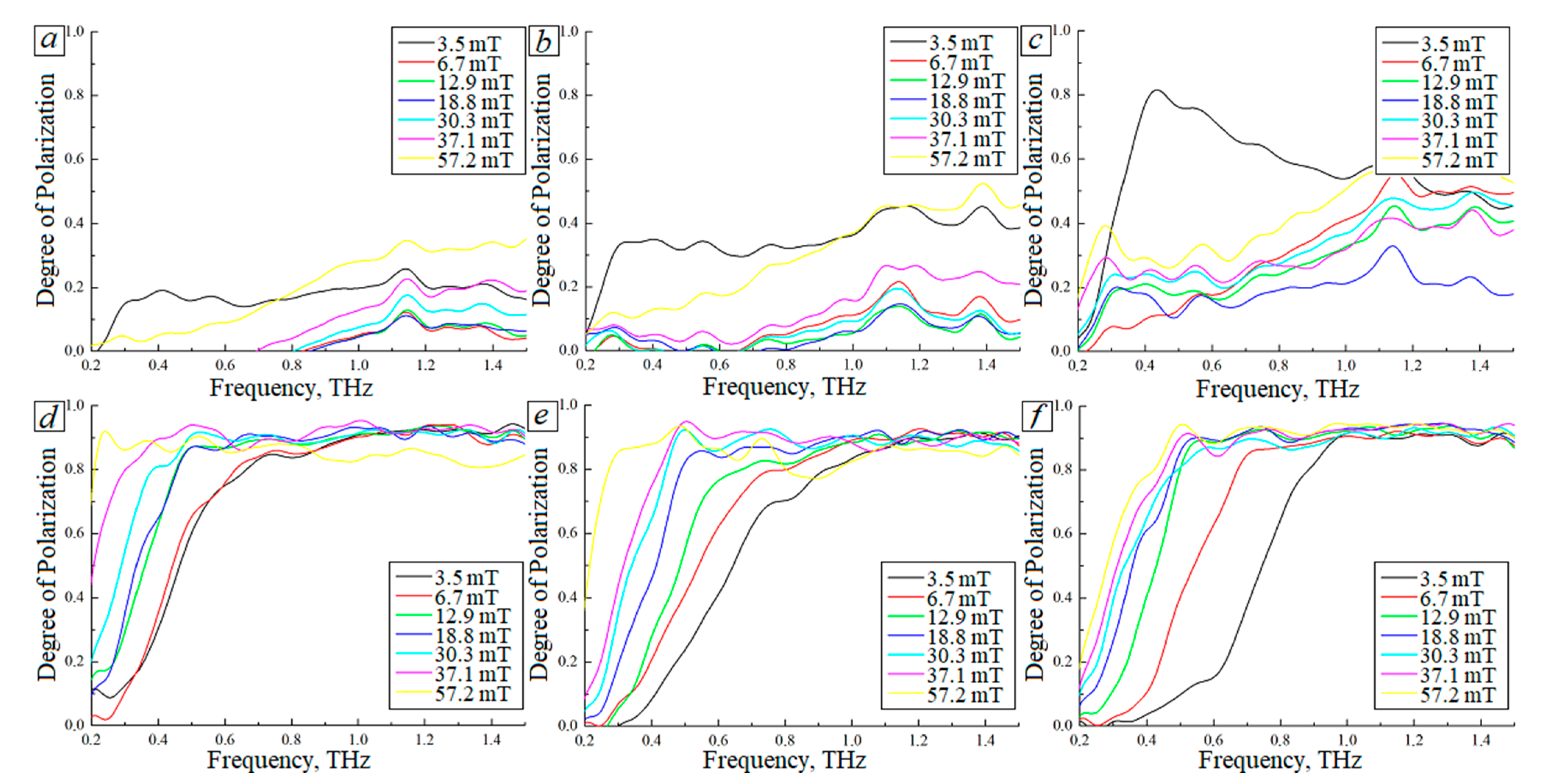
Study of the created polarizer was carried out using the THz-TDS spectrometer (“T-Spec 1000 Teravil”, Vilnius, Lithuania) in the transmission mode at a temperature of (21 ± 1) °C. Analysis was implemented in the 0.2–1.5 THz spectral range. The optical scheme of the THz spectrometer is shown in Figure 4. An optical rack with the possibility of changing the position was installed between the focusing mirrors in the spectrometer. The THz wave passed through the center of the cell (Figure 4a). The illustrations of the spectrometer THz source wave beam passing the cell when the magnets were placed vertically and horizontally are shown in Figure 4b,c. The arrows located in a plane perpendicular to the THz wave beam propagation direction show the wave polarization state. Here, we took into consideration that THz wave source in the spectrometer had vertical polarization.

3. Results

A THz wave spectrum passed through the cell filled with pure synthetic oil was used as the reference signal. The examples of the transmission spectra of a THz wave passed through a cell filled with the pure oil and an empty cell are shown in Figure 5.
After that, each cell filled with a MF was installed in the provided compartment and the signal was recorded under the external magnetic field varied in the range from 0 to 57.2 mT. An averaging was carried out over 256 spectra measured for the same conditions. Measurements with each cell were repeated at least 5 times.
The degree of polarization of an initially non-polarized THz wave passed through the cell was calculated using the following formula:
P = | I I | I + I ,  
where I is the intensity of the linear polarized THz wave transmitted through the cell with the polarization plane perpendicular to the magnetic induction vector of the external magnetic field, I is the intensity of transmitted through the cell linear polarized THz wave with the polarization plane parallel to the magnetic induction vector of the external magnetic field. The orientation of the external magnetic field was changed by mechanical rotation of the inductors.
The degree of polarization of an initially non-polarized THz wave beam passed the cells containing MF with MPs of the 2.5 wt.% concentration is shown in Figure 6. Cells filled with MFs with MPs of 29–35 μm, 20–29 μm, 10–20 μm sizes act as controlled polarizers THz radiation (Figure 6d–f). A decrease in MP size caused an increase in the degree of polarization and a shift in the operating range of the polarizer to a high-frequency area. With an increase in the magnitude of the magnetic field, the operating frequency range of the polarizer extended and the degree of polarization was increased. Samples of cells containing MFs with MPs of 45–50 μm, 40–45 μm, 35–40 μm sizes had a poor response to the external magnetic field value and a low degree of polarization associated with the formation of irregular structures due to low MPs concentration (Figure 6a–c).
The degree of polarization of an initially non-polarized THz wave beam that passed the cells containing MF with MPs of 5 wt.% concentration is shown in Figure 7. The cells containing MFs with MPs of 29–35 μm, 20–29 μm, 10–20 μm sizes demonstrated the best efficiency in the THz radiation polarization. Varying the magnetic field magnitude enabled controlling the polarizer operation spectral range (Figure 7d–f).
The degree of polarization of an initially non-polarized THz wave beam that passed the cells containing MFs with 10 wt.% of MPs is shown in Figure 8. With an increase in the magnetic field value, the degree of polarization of the THz wave that passed the polarizer increased (Figure 8a–c). For the case of MF with MPs of 10–35 μm sizes, a decrease in MPs size no longer significantly shifted the polarizer operation spectral range, and an increase in the magnetic field magnitude caused the polarizer operation spectral range extending and an increase in the degree of polarization of the transmitted THz wave.

4. Discussion

A model of a magnetically controlled linear polarizer of THz waves based on a cell with a MF controlled by an external magnetic field was proposed. The polarizer operation principle is illustrated in Figure 6b. The physical principle of THz wave beam polarization changing can be briefly described as follows. The dynamic filament-like structures of ferromagnetic microparticles appearing under the action of an external magnetic field shown in Figure 2 can be considered as a set of metal wire parallel segments. The reflection coefficient of a similar structure depends on the angle θ between the electro-magnetic wave polarization plane and the metal wires orientation [46]. When θ = 90°, the reflection coefficient is zero and this component of the THz wave is transmitted through the polarizer. When θ = 0, the reflection is high and this component is not transmitted.
The used MF included a synthetic oil and magnetic alloy 5BDSR MPs of 10–50 μm sizes with concentrations of 2.5, 5, and 10 wt.%. For small-size MPs and maximal magnetic field magnitude analyzed by us, the MPs concentration had a weak influence on the degree of polarization of the THz wave passed through the polarizer. In these conditions, the typical degree of polarization was about 90%. For small-size MPs and the maximal magnetic field used by us, the operation spectral range of the polarizer depends on the PMs concentration. For a polarization degree level of not less than 80%, the lower frequency threshold level varied from 0.2 THz to 0.4 THz when the MPs concentration decreases from 10 wt.% to 2.5 wt.%. It should be pointed out that a dynamic equilibrium of MPs spatial structure in the external magnetic field occurs in about 1 s. The operating range of the polarizer and the degree of polarization can be controlled operatively by changing the magnitude of the external magnetic field.
Therefore, changing the degree of polarization of the THz wave can be implemented as follows:
  • To create a horizontally polarized THz wave, we need to use the scheme shown in Figure 9;
  • To create a vertically polarized THz wave, we need to rotate the magnets by 90° in relation to the previous case;
  • Changing the degree of polarization of the transmitted THz wave is carried out by control of the external magnetic field magnitude.

5. Conclusions

A prototype of a magnetically controlled linear polarizer of THz waves based on a cell filled with magnetic fluid controlled by an external magnetic field was created. The magnetic fluid consisted of a synthetic oil with high transparency in the THz range and also ferromagnetic microparticles. Two Helmholtz coils were used as a source of a homogeneous external magnetic field. Under action of an external magnetic field, ferromagnetic microparticles form dynamic filament-like structures, which can be considered as a set of metal wire parallel segments. The reflection of a THz wave by similar structures depends on the angle between the wave polarization plane and the metal wires orientation.
The advantage of the proposed THz wave linear polarizer compared to the set of metal wire parallel segments is that we can vary operatively the degree of polarization of the transmitted THz wave and the polarizer operation spectral range.

Author Contributions

Conceptualization, Y.V.K. and A.V.B.; methodology, Z.S.K. and A.V.B.; software, A.V.B.; validation, Z.S.K.; formal analysis, A.V.B. and Z.S.K.; investigation, Z.S.K. and A.P.V.; data curation, A.V.B.; writing—original draft preparation, Z.S.K. and A.P.V.; writing—review and editing, I.M. and Y.V.K.; visualization, A.P.V.; supervision, I.M. and Y.V.K. All authors have read and agreed to the published version of the manuscript.

Funding

The research was supported by the Grant of the Russian Ministry of Science and Education (Agreement No. 075-15-2021-1412 dated 23 December 2021, unique contract identifier RF 2251.62321X0012).

Data Availability Statement

The data presented in this study are available on request from the corresponding author. The data are not publicly available due to privacy.

Acknowledgments

The authors thank Petr J. Mitchell, Tomsk State University, for a style review.

Conflicts of Interest

The authors declare no conflict of interest.

References

  1. Zhang, X.-C.; Xu, J. Introduction to THz Wave Photonics; Springer: Boston, MA, USA, 2010. [Google Scholar] [CrossRef]
  2. Siegel, P.H. Terahertz Technology. IEEE Trans. Microw. Theory Tech. 2002, 50, 910–928. [Google Scholar] [CrossRef]
  3. Siegel, P.H. Terahertz Technology in Biology and Medicine. IEEE Trans. Microw. Theory Tech. 2004, 52, 2438–2447. [Google Scholar] [CrossRef]
  4. Nikitkina, A.I.; Bikmulina, P.Y.; Gafarova, E.R.; Kosheleva, N.V.; Efremov, Y.M.; Bezrukov, E.A.; Butnaru, D.V.; Dolganova, I.N.; Chernomyrdin, N.V.; Cherkasova, O.P.; et al. Terahertz Radiation and the Skin: A Review. J. Biomed. Opt. 2021, 26, 043005. [Google Scholar] [CrossRef] [PubMed]
  5. Smolyanskaya, O.A.; Chernomyrdin, N.V.; Konovko, A.A.; Zaytsev, K.I.; Ozheredov, I.A.; Cherkasova, O.P.; Nazarov, M.M.; Guillet, J.-P.; Kozlov, S.A.; Kistenev, Y.V.; et al. Terahertz Biophotonics as a Tool for Studies of Dielectric and Spectral Properties of Biological Tissues and Liquids. Prog. Quantum Electron. 2018, 62, 1–77. [Google Scholar] [CrossRef]
  6. Borovkova, M.; Khodzitsky, M.; Demchenko, P.; Cherkasova, O.; Popov, A.; Meglinski, I. Terahertz Time-Domain Spectroscopy for Non-Invasive Assessment of Water Content in Biological Samples. Biomed. Opt. Express 2018, 9, 2266. [Google Scholar] [CrossRef]
  7. Oh, S.J.; Kim, S.-H.; Jeong, K.; Park, Y.; Huh, Y.-M.; Son, J.-H.; Suh, J.-S. Measurement Depth Enhancement in Terahertz Imaging of Biological Tissues. Opt. Express 2013, 21, 21299. [Google Scholar] [CrossRef]
  8. Moldosanov, K.; Bykov, A.; Kairyev, N.; Khodzitsky, M.; Kropotov, G.; Lelevkin, V.; Meglinski, I.; Postnikov, A.; Shakhmin, A. Terahertz-to-Infrared Converters for Imaging the Human Skin Cancer: Challenges and Feasibility. J. Med. Imaging 2023, 10, 023501. [Google Scholar] [CrossRef] [PubMed]
  9. Cherkasova, O.; Nazarov, M.; Shkurinov, A. Noninvasive Blood Glucose Monitoring in the Terahertz Frequency Range. Opt. Quantum Electron. 2016, 48, 217. [Google Scholar] [CrossRef]
  10. Gusev, S.I.; Borovkova, M.A.; Strepitov, M.A.; Khodzitsky, M.K. Blood Optical Properties at Various Glucose Level Values in THz Frequency Range. In Clinical and Biomedical Spectroscopy and Imaging IV; OSA: Washington, DC, USA, 2015; p. 95372A. [Google Scholar] [CrossRef]
  11. Fujiwara, M.; Hiromoto, N.; Shibai, H.; Hirao, T.; Nakagawa, T. Development of Far-Infrared Ge:Ga Photoconductor 2D Array for 3-THz Imaging. In Infrared Technology and Applications XXVI; Andresen, B.F., Fulop, G.F., Strojnik, M., Eds.; SPIE: London, UK, 2000; p. 842. [Google Scholar] [CrossRef]
  12. Kaufmann, P.; Marcon, R.; Abrantes, A.; Bortolucci, E.C.; TFernandes, L.O.; Kropotov, G.I.; Kudaka, A.S.; Machado, N.; Marun, A.; Nikolaev, V.; et al. THz Photometers for Solar Flare Observations from Space. Exp. Astron. 2014, 37, 579–598. [Google Scholar] [CrossRef]
  13. Kaufmann, P.; Abrantes, A.; Bortolucci, E.C.; Caspi, A.; Fernandes, L.O.T.; Kropotov, G.; Kudaka, A.S.; Laurent, G.; Machado, N.; Marcon, R.; et al. THz Solar Observations on Board of a Trans-Antarctic Stratospheric Balloon Flight. In Proceedings of the 2016 41st International Conference on Infrared, Millimeter, and Terahertz waves (IRMMW-THz), Copenhagen, Denmark, 25–30 September 2016; IEEE: Piscataway, NJ, USA, 2016; pp. 1–2. [Google Scholar] [CrossRef]
  14. Yang, L.; Guo, T.; Zhang, X.; Cao, S.; Ding, X. Toxic Chemical Compound Detection by Terahertz Spectroscopy: A Review. Rev. Anal. Chem. 2018, 37, pp.1–10. [Google Scholar] [CrossRef]
  15. Stutzki, J.; Graf, U.U.; Honingh, C.E.; Jacobs, K.; Schieder, R.; Siebertz, O. Terahertz Receivers for Astronomy. In Proceedings of the 2005 Joint 30th International Conference on Infrared and Millimeter Waves and 13th International Conference on Terahertz Electronics, Williamsburg, VA, USA, 19–23 September 2005; IEEE: Piscataway, NJ, USA, 2015; pp. 403–404. [Google Scholar] [CrossRef]
  16. Waters, J.W.; Froidevaux, L.; Harwood, R.S.; Jarnot, R.F.; Pickett, H.M.; Read, W.G.; Siegel, P.H.; Cofield, R.E.; Filipiak, M.J.; Flower, D.A.; et al. The Earth Observing System Microwave Limb Sounder (EOS MLS) on the Aura Satellite. IEEE Trans. Geosci. Remote Sens. 2006, 44, 1075–1092. [Google Scholar] [CrossRef]
  17. You, B.; Lu, J.-Y. Remote and in Situ Sensing Products in Chemical Reaction Using a Flexible Terahertz Pipe Waveguide. Opt. Express 2016, 24, 18013. [Google Scholar] [CrossRef] [PubMed]
  18. Born, N.; Behringer, D.; Liepelt, S.; Beyer, S.; Schwerdtfeger, M.; Ziegenhagen, B.; Koch, M. Monitoring Plant Drought Stress Response Using Terahertz Time-Domain Spectroscopy. Plant Physiol. 2014, 164, 1571–1577. [Google Scholar] [CrossRef] [PubMed]
  19. Gente, R.; Koch, M. Monitoring Leaf Water Content with THz and Sub-THz Waves. Plant Methods 2015, 11, 15. [Google Scholar] [CrossRef]
  20. Nagatsuma, T.; Ducournau, G.; Renaud, C.C. Advances in Terahertz Communications Accelerated by Photonics. Nat. Photonics 2016, 10, 371–379. [Google Scholar] [CrossRef]
  21. Song, H.-J.; Nagatsuma, T. Present and Future of Terahertz Communications. IEEE Trans. Terahertz Sci. Technol. 2011, 1, 256–263. [Google Scholar] [CrossRef]
  22. Federici, J.; Moeller, L. Review of Terahertz and Subterahertz Wireless Communications. J. Appl. Phys. 2010, 107, 111101. [Google Scholar] [CrossRef]
  23. Saqlain, M.; Idrees, N.M.; Cao, X.; Gao, X.; Yu, X. Feasibility Analysis of Opto-Electronic THz Earth-Satellite Links in the Low- and Mid-Latitude Regions. Appl. Opt. 2019, 58, 6762. [Google Scholar] [CrossRef] [PubMed]
  24. Ishigaki, K.; Shiraishi, M.; Suzuki, S.; Asada, M.; Nishiyama, N.; Arai, S. Direct Intensity Modulation and Wireless Data Transmission Characteristics of Terahertz-Oscillating Resonant Tunnelling Diodes. Electron. Lett. 2012, 48, 582. [Google Scholar] [CrossRef]
  25. Ahi, K.; Shahbazmohamadi, S.; Asadizanjani, N. Quality Control and Authentication of Packaged Integrated Circuits Using Enhanced-Spatial-Resolution Terahertz Time-Domain Spectroscopy and Imaging. Opt. Lasers Eng. 2018, 104, 274–284. [Google Scholar] [CrossRef]
  26. Naftaly, M.; Vieweg, N.; Deninger, A. Industrial Applications of Terahertz Sensing: State of Play. Sensors 2019, 19, 4203. [Google Scholar] [CrossRef] [PubMed]
  27. Kemp, M.C.; Taday, P.F.; Cole, B.E.; Cluff, J.A.; Fitzgerald, A.J.; Tribe, W.R. Security Applications of Terahertz Technology. In Terahertz for Military and Security Applications; Hwu, R.J., Woolard, D.L., Eds.; SPIE: London, UK, 2003; p. 44. [Google Scholar] [CrossRef]
  28. Ikeda, T.; Matsushita, A.; Tatsuno, M.; Minami, Y.; Yamaguchi, M.; Yamamoto, K.; Tani, M.; Hangyo, M. Investigation of Inflammable Liquids by Terahertz Spectroscopy. Appl. Phys. Lett. 2005, 87, 034105. [Google Scholar] [CrossRef]
  29. Federici, J.F.; Schulkin, B.; Huang, F.; Gary, D.; Barat, R.; Oliveira, F.; Zimdars, D. THz Imaging and Sensing for Security Applications—Explosives, Weapons and Drugs. Semicond. Sci. Technol. 2005, 20, S266–S280. [Google Scholar] [CrossRef]
  30. Krimi, S.; Klier, J.; Jonuscheit, J.; von Freymann, G.; Urbansky, R.; Beigang, R. Highly Accurate Thickness Measurement of Multi-Layered Automotive Paints Using Terahertz Technology. Appl. Phys. Lett. 2016, 109, 021105. [Google Scholar] [CrossRef]
  31. Su, K.; Shen, Y.-C.; Zeitler, J.A. Terahertz Sensor for Non-Contact Thickness and Quality Measurement of Automobile Paints of Varying Complexity. IEEE Trans. Terahertz Sci. Technol. 2014, 4, 432–439. [Google Scholar] [CrossRef]
  32. Yasui, T.; Yasuda, T.; Sawanaka, K.; Araki, T. Terahertz Paintmeter for Noncontact Monitoring of Thickness and Drying Progress in Paint Film. Appl. Opt. 2005, 44, 6849. [Google Scholar] [CrossRef]
  33. Prahl, S.A.; van Gemert, M.J.C.; Welch, A.J. Determining the Optical Properties of Turbid Media by Using the Adding–Doubling Method. Appl. Opt. 1993, 32, 559. [Google Scholar] [CrossRef] [PubMed]
  34. Friebel, M.; Helfmann, J.; Netz, U.; Meinke, M. Influence of Oxygen Saturation on the Optical Scattering Properties of Human Red Blood Cells in the Spectral Range 250 to 2000 Nm. J. Biomed. Opt. 2009, 14, 034001. [Google Scholar] [CrossRef] [PubMed]
  35. Kan, T.; Isozaki, A.; Kanda, N.; Nemoto, N.; Konishi, K.; Takahashi, H.; Kuwata-Gonokami, M.; Matsumoto, K.; Shimoyama, I. Enantiomeric Switching of Chiral Metamaterial for Terahertz Polarization Modulation Employing Vertically Deformable MEMS Spirals. Nat. Commun. 2015, 6, 8422. [Google Scholar] [CrossRef] [PubMed]
  36. Zhang, S.; Zhou, J.; Park, Y.-S.; Rho, J.; Singh, R.; Nam, S.; Azad, A.K.; Chen, H.-T.; Yin, X.; Taylor, A.J.; et al. Photoinduced Handedness Switching in Terahertz Chiral Metamolecules. Nat. Commun. 2012, 3, 942. [Google Scholar] [CrossRef]
  37. Bréhat, F.; Wyncke, B. Measurement of the Optical Constants of Crystal Quartz at 10 K and 300 K in the Far Infrared Spectral Range: 10–600 cm−1. Int. J. Infrared Millimeter Waves 1997, 18, 1663–1679. [Google Scholar] [CrossRef]
  38. Laurent, S.; Dutz, S.; Häfeli, U.O.; Mahmoudi, M. Magnetic Fluid Hyperthermia: Focus on Superparamagnetic Iron Oxide Nanoparticles. Adv. Colloid Interface Sci. 2011, 166, 8–23. [Google Scholar] [CrossRef] [PubMed]
  39. Huang, L.; Chen, X.; Bai, B.; Tan, Q.; Jin, G.; Zentgraf, T.; Zhang, S. Helicity Dependent Directional Surface Plasmon Polariton Excitation Using a Metasurface with Interfacial Phase Discontinuity. Light Sci. Appl. 2013, 2, e70. [Google Scholar] [CrossRef]
  40. Ezhov, D.M.; Kochnev, Z.S.; Savelyev, E.S.; Cherepanov, V.N.; Mamrashev, A.A.; Nikolaev, N.A.; Svetlichnyi, V.A. Variable THz Attenuator Based on 5BDSR Microparticles in Synthetic 80W-90 Oil. In Proceedings of the 2020 45th International Conference on Infrared, Millimeter, and Terahertz Waves (IRMMW-THz), Buffalo, NY, USA, 8–13 November 2020; IEEE: Piscataway, NJ, USA, 2020; pp. 1–2. [Google Scholar] [CrossRef]
  41. Rubinstein, M.; Harris, V.G.; Lubitz, P. Ferromagnetic Resonance in Nanocrystalline Fe73.5CuNb3Si13.5B9 (Finemet). J. Magn. Magn. Mater. 2001, 234, 306–312. [Google Scholar] [CrossRef]
  42. Svetlichnyi, V.A.; Balashov, V.B.; Lapin, I.N.; Sokolov, A.É.; Cherepanov, V.N. Magnetic Properties of Soft Magnetic Alloys 5BDSR and 82K3HSR. Russ. Phys. J. 2019, 62, 411–415. [Google Scholar] [CrossRef]
  43. Adbul-Munaim, A.M.; Reuter, M.; Koch, M.; Watson, D.G. Distinguishing Gasoline Engine Oils of Different Viscosities Using Terahertz Time-Domain Spectroscopy. J. Infrared Millim Terahertz Waves 2015, 36, 687–696. [Google Scholar] [CrossRef]
  44. Abdulmunem, O.M.; Abdul-Munaim, A.M.; Aller, M.M.; Preu, S.; Watson, D.G. THz-TDS for Detecting Glycol Contamination in Engine Oil. Appl. Sci. 2020, 10, 3738. [Google Scholar] [CrossRef]
  45. Kochnev, Z.S.; Kistenev, Y.V.; Borisov, A.V. Magnetically tunable bandpass filter of terahertz radiation. Russ. Phys. J. 2022, 65, 1667–1675. [Google Scholar] [CrossRef]
  46. Kontorovich, M.I.; Astrakhan, M.I.; Akimov, V.P.; Fesman, G.A. Electrodynamics of mesh structures; Izdatel’stvo Radio i Sviaz’: Moscow, Russia, 1987; 136p. [Google Scholar]
Figure 1. The body of the electromagnets.
Photonics 10 00675 g001
Figure 2. Formation of MPs structures in a cell with an MF at various values of the magnetic field (MPs concentration is 2.5 wt.%). (a) B = 0 mT, (b) B = 6.7 mT, (c) B = 12.9 mT, (d) B = 18.8 mT, (e) B = 24.7 mT, (f) B = 30.3 mT, (g) B = 37.1 mT, (h) B = 43 mT, (i) B = 49.2 mT, (j) B = 57.2 mT.
Photonics 10 00675 g002
Figure 3. Results of numerical simulation of a model MF spatial structure formation in an external magnetic field. Parameters of the simulation: magnetic field induction B = 0.1 mT, MF was considered as a liquid with μ = 5000. The arrows show a local direction of the magnetic induction vector.
Photonics 10 00675 g003
Figure 4. (a) The optical scheme of the THz spectrometer and location of the polarizer, (b) an illustration of the spectrometer THz source wave beam passing the cell when the magnets are placed vertically; (c) the same for the case when the magnets are placed horizontally.
Photonics 10 00675 g004
Figure 5. An example of a THz wave spectrum passed through an empty cell and the same cell filled with pure oil.
Photonics 10 00675 g005
Figure 6. The degree of polarization of an initially non-polarized THz wave beam passed the cell containing MFs with 2.5 wt.% of MPs: (a) 45–50 μm, (b) 40–45 μm, (c) 35–40 μm, (d) 29–35 μm, (e) 20–29 μm, (f) 10–20 μm.
Photonics 10 00675 g006
Figure 7. The degree of polarization of an initially non-polarized THz wave beam passed the cell containing MFs with 5 wt.% of MPs: (a) 45–50 μm, (b) 40–45 μm, (c) 35–40 μm, (d) 29–35 μm, (e) 20–29 μm, (f) 10–20 μm.
Photonics 10 00675 g007
Figure 8. The degree of polarization of the initially non-polarized THz wave beam passed the cell containing MFs with 10 wt.% of MPs: (a) 45–50 μm, (b) 40–45 μm, (c) 35–40 μm, (d) 29–35 μm, (e) 20–29 μm, (f) 10–20 μm.
Photonics 10 00675 g008
Figure 9. A way to create a horizontally polarized THz wave from initially non polarized one.
Photonics 10 00675 g009
Table 1. Characteristics of popular controlled THz radiation polarizers.
Type of PolarizerPrinciple of OperationAdvantagesDisadvantages
Chiral metamaterialsPolarization change by chiral structures through their photoactivationPolarization rotation angle can be controlled
Fast response
Only elliptical polarization is possible at the output
MEMS spiralsChange in THz radiation polarization depending on the direction of spiral twistingDo not change the intensity of radiation
Enantiomeric switching of spirals
Dependence of optical activity on the angle of incidence of THz radiation on the polarizer
Polarizer based on a crystal quartzUsing natural optical birefringence of the crystal quartzOperation in a wide frequency rangeOnly mechanical control is possible
Polarizer based on composite membranesForming spatial structures of Fe3O4 magnetite nanoparticles in a constant magnetic field during the polymerization of a composite membraneSimple method of obtaining composite membranesLow transmittance of THz radiation in the membrane of a large thicknesses
Mechanical control
Polarizer based on magnetic fluidsForming spatial dynamic structures of Fe3O4 particles in an external magnetic fieldLarge variety of MFs
Magnetic field control
Slow response
Dependence of the degree of polarization on the room temperature
Table 2. Parameters of the created MF samples.
No.2.5 wt.%5 wt.%10 wt.%
145–50 μm45–50 μm45–50 μm
240–45 μm40–45 μm40–45 μm
335–40 μm35–40 μm35–40 μm
429–35 μm29–35 μm29–35 μm
520–29 μm20–29 μm20–29 μm
610–20 μm10–20 μm10–20 μm
Disclaimer/Publisher’s Note: The statements, opinions and data contained in all publications are solely those of the individual author(s) and contributor(s) and not of MDPI and/or the editor(s). MDPI and/or the editor(s) disclaim responsibility for any injury to people or property resulting from any ideas, methods, instructions or products referred to in the content.

