A Review of Optical Tweezers with Metasurfaces


School of Electronic and Optical Engineering, Nanjing University of Science and Technology, Nanjing 210094, China
*
Author to whom correspondence should be addressed.
Photonics 2023, 10(6), 623; https://doi.org/10.3390/photonics10060623
Submission received: 25 April 2023
/
Revised: 16 May 2023
/
Accepted: 23 May 2023
/
Published: 28 May 2023
(This article belongs to the Special Issue Light Control and Particle Manipulation)
Abstract
:Optical tweezers (OTs) have made significant progress in recent years, realizing the non-contact optical manipulation of target objects through the interaction between light and matter. In addition to trapping particles with the intensity gradient of the beam, a series of complex optical elements are required to properly modulate the beams to expand the operation of optical manipulation. The development of metasurfaces alleviates this problem. Due to the merits of miniaturization, planarization, multi-function, and integration of metasurfaces, these kinds of novel devices have been applied in OT systems. Metasurface devices have been used to replace traditional objective lenses, achieving device integration and even obtaining multi-function of OTs with unique optical properties in applications. OTs with metasurfaces have developed rapidly, and a great deal of work has been carried out on OTs with metasurfaces, as well as discussions on their practical applications. In this review, we regard the latest progress in the field of OTs with metasurfaces. We classify OTs with metasurface and summarize the new impetus brought by metasurfaces for the development of OTs.
1. Introduction
Substantial work has been devoted to manipulating targets with beams [1,2,3,4], and Nobel prizes have been conferred for related work to commend its progressiveness and breakthrough capabilities. Ashkin first utilized laser beams to trap particles [5,6]. This method of manipulating particles with a beam can be referred to as “optical tweezers”. Generally speaking, in OTs, the gradient force generated by the gradient of light intensity tends to trap particles at the focus, and the momentum of the beam transmitted to the particles leads to the generation of scattering force, which often drives the particles to move in the direction of beam propagation. This new method of particle manipulation can impose non-contact optical trapping on particles, and is of great significance in biomedicine [7,8], chemistry [9], quantum science and technology [10], and nanotechnology [11]. To achieve more diversified manipulation, methods such as “pushing [12]”, “pulling [13]”, and “rotating [14,15]”, have been developed, and more complex optical devices are needed to modulate the desired light field and increase the complexity of the optical system [16,17].
Researchers have developed new devices to solve the associated problems, including diffractive optical elements (DOEs) and more controllable spatial light modulators (SLMs). However, due to the limited ability of DOE to modulate the beam, additional devices such as polarizers remain necessary. Similarly, SLM also has the problem of power threshold, which is limited when applied to optical tweezers (OTs) and other fields that require high-power light sources. Therefore, researchers urgently need an optical device with stronger light-field regulation ability. The development of metasurfaces strongly meets these conditions. A metasurface is a kind of novel optical device and has been applied to generate desired light fields [18,19,20]. A typical metasurface consists of many subwavelength cells. Each nano cell can flexibly and independently adjust the parameters of the local light field, such as the polarization or phase. The merits of the metasurface, the small and delicate multi-functional device, can be summarized as miniaturization, integration, multi-function, and planarization. The miniaturization of the metasurface leads to the minimal volume of metasurface devices. Replacing some traditional optical devices with metasurfaces can make systems smaller and more compact [21,22]. Integration is demonstrated in the fact that metasurfaces can be easily integrated with other metasurfaces and even other devices [23]. In addition, discrete local control of metasurfaces enables the integration of various optical device functions onto a single metasurface [15] and provide metasurfaces with advantages in generating structured beams [24]. This characteristic allows systems of OTs with metasurfaces to be further simplified. The metasurface’s multi-functionality is indicated: some metasurfaces are sensitive to parameters of incident beams, allowing the same metasurface to generate different light fields. This advantage enables OTs with metasurfaces to have excellent dynamic control ability [25] and can be further applied to active [23] or passive sorting [26]. As a two-dimensional distributed device, the metasurface can be characterized by planarization. Hence, metasurfaces have great potential in the application of near-field OTs [27]. Their flexible and precise control ability can improve the precision of optical tweezers and expand the application range.
Undoubtedly, such a miniaturized, integrated, planar, and multi-functional metasurface is of great significance for generating OTs. This review will introduce the principles applied in OTs and review the latest developments of metasurface OTs. We first introduce metasurfaces designed to replace traditional objective lenses in OTs, as well as integrated devices with metasurfaces. Then, we introduce dynamic manipulation and sorting with metasurface OTs. Finally, special near-field metasurface OTs are introduced.
2. Theoretical Basis
To better introduce OTs with metasurfaces, it is necessary to summarize briefly the principles and concepts involved in OTs. Generally, the movement of a particle driven by the beam can be attributed to two aspects: optical force and optical torque. A particle is affected by optical forces, which trap or manipulate the particle. Under some conditions, the beam can also torque the particle and rotate it; we briefly discuss these two aspects in the following sections.
2.1. Optical Forces for Trapping the Particles
A common method to calculate the optical forces on particles in the light field is to utilize the Maxwell stress tensor. The time average optical force can be written as [28]:
The optical force exerted by the beam can be obtained by calculating the integral on the closed surface around the particle, which can be written as [28]:
where is the time average Maxwell stress tensor, the parameter represents the unit vector pointing to the outside of the closed surface, and is the unit tension.
The calculations can be simplified with the dipole model for a subwavelength particle. Here, the time average optical force exerted by the beam on the particle can be written as [29]:
where E and H are the electric field and magnetic field of the incident beam, respectively. Parameters p and m are the electric dipole moment and magnetic dipole moment, respectively, which can be written as [30]:
where and are the polarization rate and magnetic polarization rate of particles, respectively, which can be written as [30]:
Parameters and are the Mie scattering coefficients of the first order. The Mie scattering coefficients of the v-th order can be written as [30]:
where , and R is the particle’s radius, and is the wave number of the beam in the vacuum. The parameter is the refractive index of the particle. and are the spherical Bessel function and the spherical Hankel function of the v-th order, respectively. The prime indicates the derivative, for example . A traditional OT exerts optical forces on target particles through the gradient of the light intensity of the light field. Generally, nanoparticles (typically a few hundred nm to a few μm) are attracted to the focus. In the xy plane, particles are trapped at the center. Along the z-direction, the particle is trapped somewhere below the focus.
Similarly, there are many other ways to calculate the force on particles. The Lorentz–Mie theory can be used for Mie particles, to calculate the force exerted on the particles by the beam [31]. For non-spherical particles, metallic particles, or structured beams with unique properties, the generalized Lorentz–Mie theory (GLMT) can be used to calculate the optical force on the target particles [32,33,34]. The finite difference time domain (FDTD) and finite element method are also used to calculate optical forces. For example, using the FDTD method, by simulating the optical field with the particles in the beam, the optical force on the particle can be obtained by integrating the Maxwell stress tensor according to the result of the optical field. It must be noted that appropriate models should be selected according to the type of particles (metal or dielectric), their size, and the beam type (plane wave or structured beam, etc.), which plays an essential role in the accuracy of numerical calculation results.
2.2. Optical Torques for Rotating the Particles
It is believed that the angular momentum carried by the beam drives the particle to rotate. According to electromagnetic theory, beams with a certain spatial distribution can carry angular momentum. In 1936, Beth proposed that the angular momentum brought by light has a spin part related to the beam’s polarization [35], and this part of angular momentum comes from the spin of photons. In 1985, Chang and Lee calculated the optical torque on the optical levitation weak absorption ball according to classical electromagnetic theory [36]. It is generally accepted that the angular momenta carried by the beams can be divided into spin angular momentum (SAM) and orbital angular momentum (OAM).
The OAM was first proposed by Allen et al. in 1992 [37]. They proposed that a laser beam can carry a part of the angular momentum related to the orbit, which is associated with the spatial distribution of the beam. They demonstrated that Laguerre–Gaussian (LG) beams could carry OAM. The beam in the LG mode has a spiral phase of (where l is an integer which represents the topological charge of the beam, and φ is the azimuth angle). In addition to the axial phase singularity, it is spatially continuous and has a spiral wavefront, which is also called a vortex beam. This beam can transfer the OAM of lφ to the trapped particles. The component of angular momentum generated by LG mode beams with unit power is stated [37]:
where is the angular frequency of the beam, r is the union factor of the beam, and is the complex scalar function describing the amplitude of the light field. The parameter defines the polarization of the beam. For a left or right-handed circularly polarized beam, . For a linearly polarized beam, . The total angular momentum transferred by the beam can be written as [38]:
where is the wave number of the beam, is the Rayleigh distance, is the mode index of the incident LG beam, and is the reduced Planck constant. For a collimated beam, .
SAM is defined as the angular momentum generated by the polarization of light. In 1998, Friese et al. controlled the rotation of highly absorbing particles [39] through polarization in water and controlled the rotation frequency of the target in the range of several hertz. In 2001, Nieminen et al. conducted a detailed analysis of the SAM [40,41]. For a material of thickness d, the torque exerted on it can be given as [38]:
The parameters no and ne are the target’s ordinary and extraordinary refraction indices. E0 is the intensity of the electric field, φ is the degree of ellipticity of the beam, ε is the permittivity, and θ represents the angle between the fast axis of a quarter-wave plate and the optic axis of a birefringent particle. For a circularly polarized incident beam, the particles are subjected to a constant torque provided by SAM. Later, Nieminen et al. applied the T-matrix method to torque calculation [42], and researchers further conducted a series of studies on the torque of particles with different shapes and beams with different spatial distributions [43,44]. Interested readers can consult relevant references for further information.
3. Optical Tweezers with Metasurfaces
In this section, we briefly introduce the application of metasurfaces in OTs in recent years. We make a simple classification according to the features of metasurfaces applied in OT systems. First, we introduce far-field OTs with metasurfaces. To represent the advantages of miniaturization of the metasurface, we report works using metasurfaces as substitutes for traditional lenses. Next, we introduce OTs with metasurfaces where multi-device functions have been integrated on a single metasurface. Then, OTs with structured beams generated with metasurfaces are introduced, further indicating the merits of metasurface integration. Research on dynamic manipulation and sorting of particles is reviewed in the following sections, indicating the advantage of the multi-function of the metasurface. Finally, we come to near-field OTs with metasurfaces, showing the merits of planarization of the metasurface.
3.1. Optical Tweezers with Metasurfaces as Objective Lenses
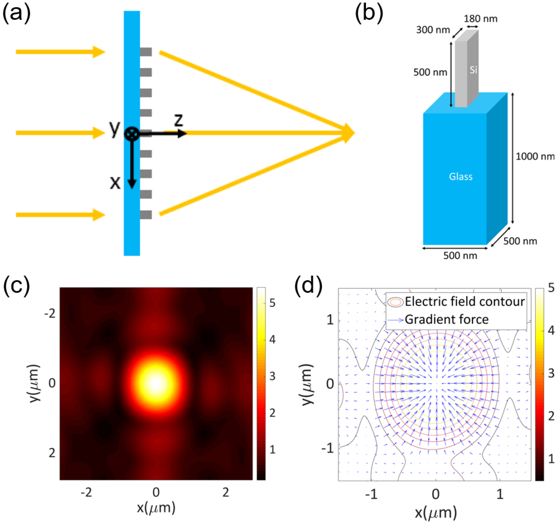
A frequent idea has been to use metasurface devices to replace traditional objective lenses. In 2019, Z. Shen et al. made a numerical study of metasurfaces composed of cells of Si cuboid nanofins on a SiO2 substrate [18], which can be seen in Figure 1a,b. The metasurface cells yield Pancharatnam–Berry (PB) phases with incident circularly polarized beams. Each cell acts as a half-wave plate. The phase of circularly polarized beams can be modulated according to the rotation angle about the z-axis of each cell. By arranging the nanofins on the substrate at appropriate rotation angles, the metasurface can generate the required phase response to obtain the required light field when the circularly polarized beam is incident. As Figure 1c shows, instead of using a traditional objective lens, the metasurface concentrates the beam and forms the focus. Through theoretical calculation it was shown that, in the water environment, the optical forces on the Si Rayleigh particles pointed to the focal point of the outgoing beam, as illustrated in Figure 1d, and stable trapping of target particles was achieved.
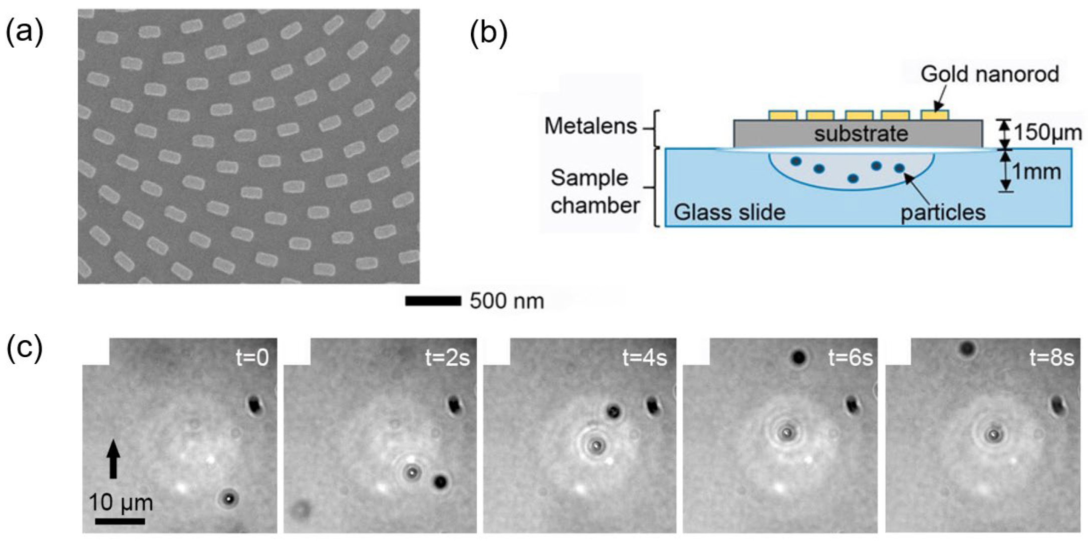
Further experimental work has been carried out on metasurfaces in OTs. Suwannasopon et al. also designed a metasurface on the principle of the PB phase, as shown in Figure 2a. The metasurface was composed of periodically arranged Au nanofins [21]. In the experiment, a 30 mW laser with a wavelength of 1064 nm was used to irradiate the metalens, and a focus point was obtained at 800 μm. The devices and the set of the metasurface used in the experiment can be seen in Figure 2b. It can be seen in Figure 2c that the target particle was trapped by the beam with the metasurface, at the center of the figure, in less than 4 s.
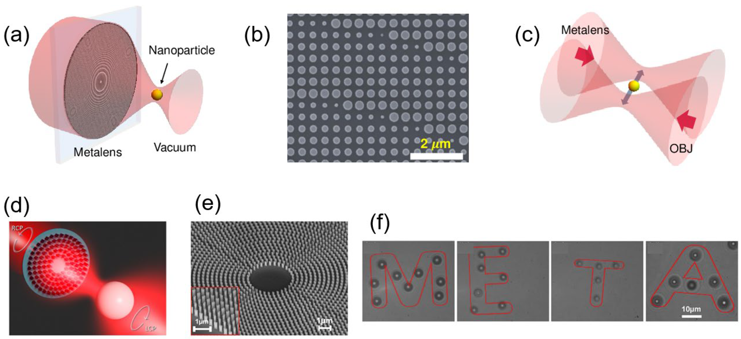
In 2021, Kunhon Shen et al. trapped nanoparticles in a vacuum environment with a metasurface device for the first time [45]. Instead of PB metasurfaces, they designed a metasurface insensitive to the polarization of incident beams, as shown in Figure 3a,b. This metasurface modulates the beam’s phase through the accumulated phase changes when the beam passes through the cells of the metasurface. A cell provides the same phase response for two incident beams with orthogonal polarization directions (for example, two linearly polarized beams with mutually perpendicular polarization directions), and these can be called “polarization-insensitive metasurfaces”. The beam focused by the metasurface forms a stable three-dimensional (3D) potential well where SiO2 nanoparticles with a diameter of 170 nm can be trapped. As Figure 3c shows, the transfer of particles was obtained between the potential wells formed by the traditional objective lens and the metasurface. In 2020, Chantakit et al. trapped nanoparticles with the help of the PB metasurface devices and arranged the particles in the pattern of letters “META” [22], which can be seen in Figure 3f. The operation demonstrated that OTs with metasurfaces could manipulate particles flexibly.
The works above demonstrated that metasurfaces could effectively replace traditional objective lenses and be used in OTs. The entire size of a metasurface can be reduced to tens or even a few microns. Compared with conventional lenses, these metasurfaces are remarkably compact. Based on miniaturization, OTs with metasurfaces can also trap target particles stably. Miniaturization also provides convenience for flexible manipulation of the OTs’ trapping position. The successful shifts of particles between the potential wells generated with traditional lenses and metasurfaces also prove that OTs with metasurfaces can be effectively applied with current OT systems. It should be noted that although dielectric cells have good transmissivity, the metasurface may have some disadvantages in efficiency compared with traditional objective lenses. However, the merits of metasurfaces outweigh such flaws. A typical process to manufacture a metasurface is to apply atomic layer deposition (ALD) [46]. This process is compatible with the manufacturing process of chips, which makes OTs with metasurfaces conducive for application in that context. Based on the works mentioned above, other kinds of metasurfaces, such as wideband achromatic metasurfaces [47], are also expected to be used in OTs, further enriching the development of OTs.
3.2. Optical Tweezers with Metasurfaces Integrating Multi-Devices
On the basis of using metasurfaces as substitutes for traditional objective lenses, researchers have further explored the application of metasurfaces in OTs. Since a metasurface is composed of many independent cells, the local phase distribution can be flexibly modulated, and multiple devices can be integrated into a single metasurface. For example, the phase distribution of a spiral phase plate and an objective lens were added onto a single metasurface [15]. In 2020, Chantakit et al. experimentally generated an optical vortex (OV) with metasurfaces [22]. The set of the metasurface can be seen in Figure 4a. Their metasurface can be regarded as combining a convex lens and a spiral phase plate. As Figure 4b shows, the OT can also rotate the particle along the halo in addition to trapping particles. Simulation of the generation of a focused OV with a PB metasurface was performed by Z. Shen et al. in 2021 [15]. The diagram of the metasurface and the cell can be seen in Figure 4c. They generated OVs with a single metasurface through numerical calculation and comprehensively discussed the force exerted on the particles near the focal plane. Arrows in Figure 4d indicate the time-averaged Poynting vectors. Particles trapped on the halo rotate along them. Therefore, such an optical vortex can also be called an optical spanner (OS).
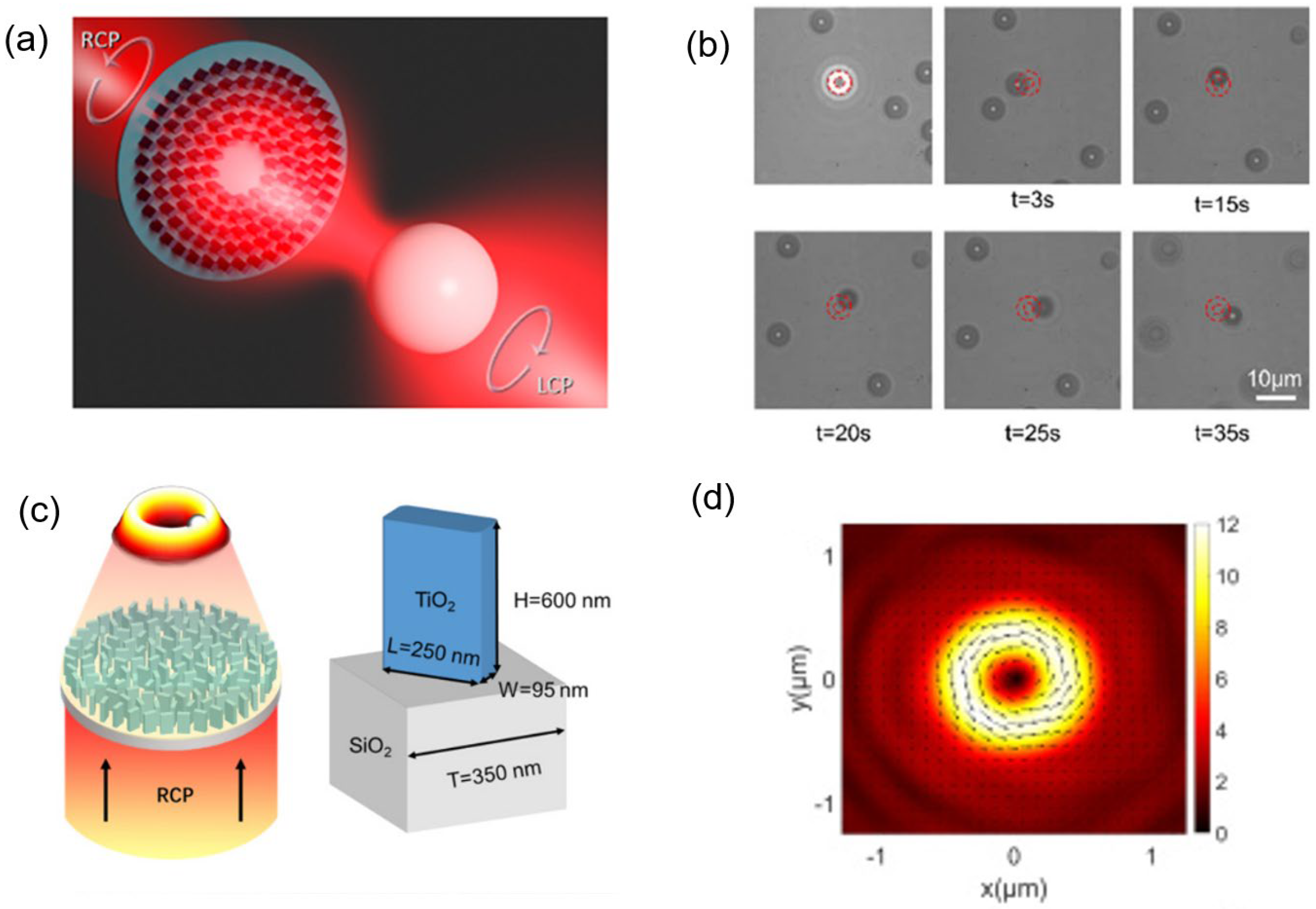
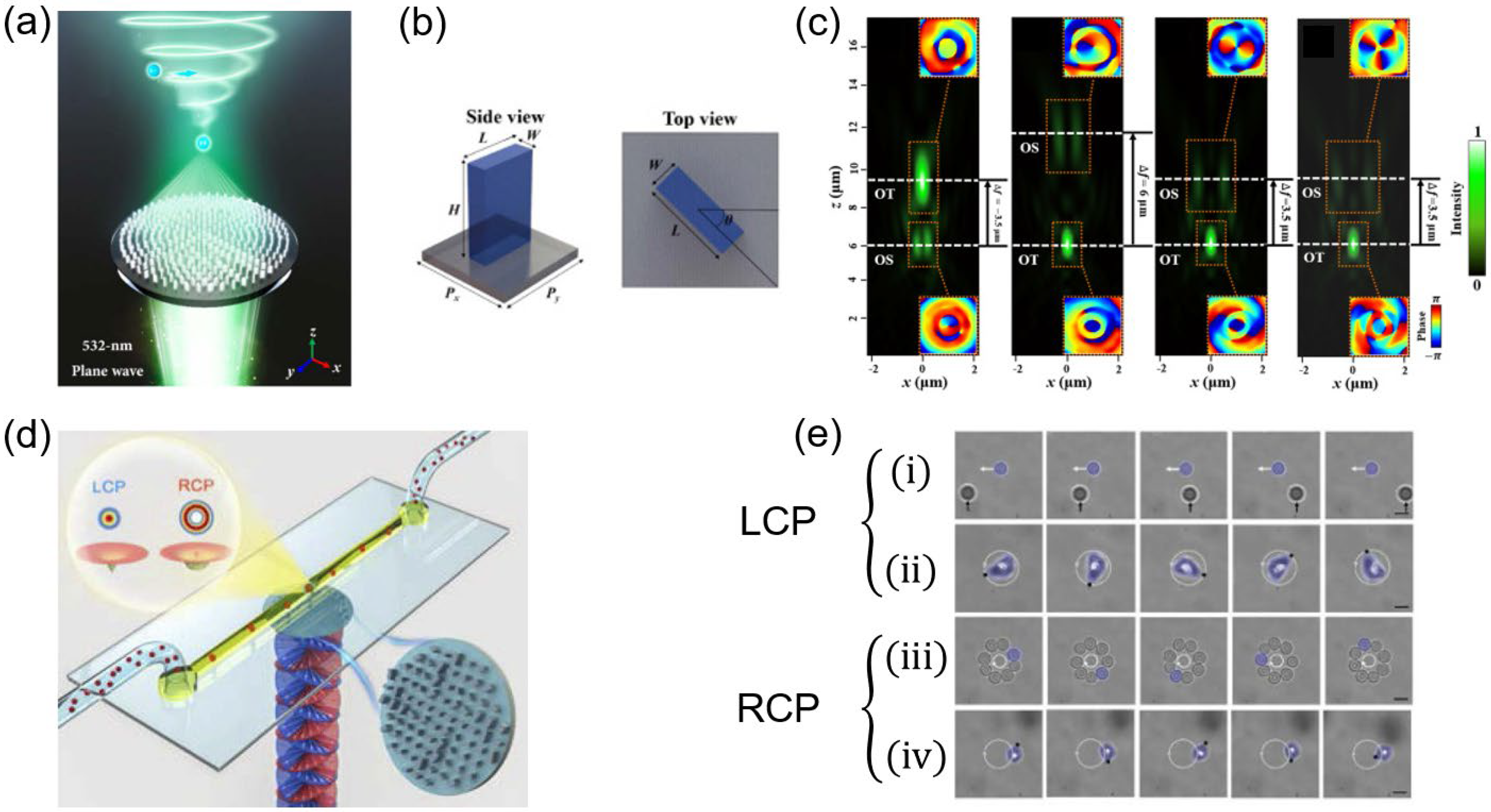
Based on device integration, further integration of multi-functions in OTs has also become possible with the assistance of metasurfaces. Splicing together two monolithic metasurfaces is the most straightforward idea. Ma et al. designed a corresponding metasurface in such a way [48]. The metasurface can be divided into two areas; each region independently modulated the light to form a focus or an OV and trapped or rotated particles. Tianyue Li and Xingyi Li proposed further ideas [49,50]. We come first to Tianyue Li’s work. PB metasurfaces can provide two categories of independent phase modulation. One category is the accumulated propagation phase when the beam transmits through the cells of the metasurfaces. The other is the PB phase determined by the nanofins’ rotation angles. These two types of phases do not interfere with each other, so Li et al. utilized a single piece of metasurface to produce two non-interfering focuses [49]. A focus and an OV were generated simultaneously at different focal lengths, and the combination of OT and OS was achieved simultaneously. Figure 5a clearly shows the OT and OS combination. Xingyi Li’s team designed a metasurface that generated two different light fields with varying incident beams [50], as Figure 5d shows. By employing the concepts of propagation phase and PB phase, when the left-handed circularly polarized beam (LCP) was incident, the light spot was observed on the focal plane and acted as an OT. A halo was observed when the right-handed circularly polarized beam (RCP) was incident, and the function of OS was achieved. Figure 5e shows the difference in the trapping effect between the LCP and RCP incident beams. With the incident LCP beam, the SiO2 particle was trapped and manipulated by the moving focal point, as Figure 5e(i) shows. Figure 5e(ii) shows that an irregularly shaped CaCO3 particle was observed spinning when it was trapped. In the case of RCP beam incidence, the SiO2 particles were trapped and rotated on the halo like a necklace, as seen in Figure 5e(iii). Meanwhile, the CaCO3 particle was observed spinning while rotating along the halo in Figure 5e(iv). These observed features demonstrate that the particles can be trapped or rotated along the halo. Therefore, an outstanding dynamic manipulation can be obtained. These works embody the characteristics of integration and multi-function of the metasurface.
The integration advantage of metasurfaces allows their use in OTs to realize the integration of devices and even the integration of multiple functions. Such integration enables combining more devices and functions on a single metasurface, providing new possibilities for dynamic manipulation. Furthermore, it reduces the size of the already compact OTs compared with OTs using traditional objective lenses, enabling the OTs with metasurfaces to meet more requirements of the lab-on-chip. Such a feature also reduces the difficulty of optical path assembly and the requirements for optical axis alignment, and facilitates the work of the whole system.
3.3. Optical Tweezers with Structured Beams Generated with Metasurfaces
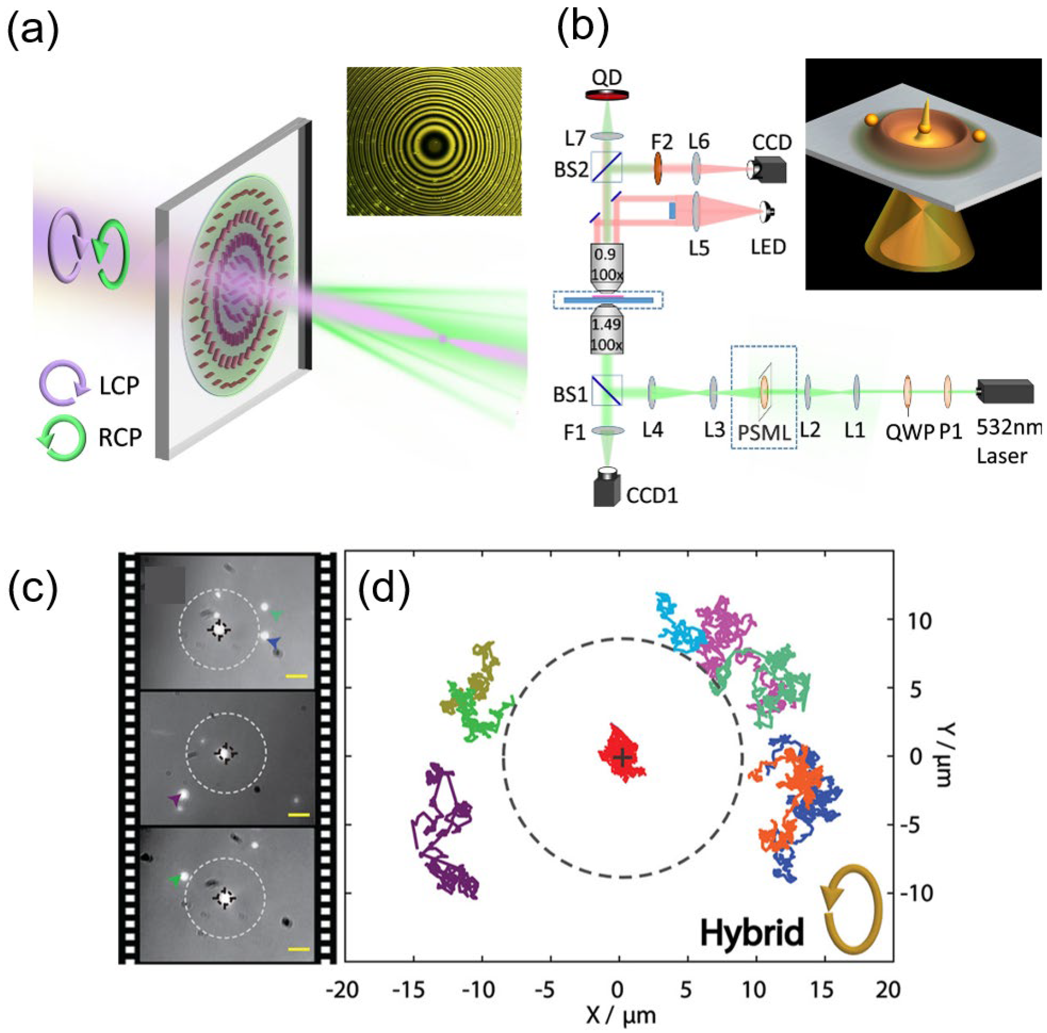
Thanks to the flexible discrete adjustment of the local phase distribution, metasurfaces have unique advantages in generating structured beams that require compact phase modulation. OTs with structured beams generated using metasurfaces can be viewed as a further development of the advantage of integration. Wang et al. developed a novel plasmonic OT based on a metasurface [51], which was able to trap the target particle precisely. The plasmonic OT traps and manipulates particles with the surface plasmon polariton (SPP). In Wang’s work, left and right-handed polarized beams are simultaneously incident on the metasurface, and the polarization-sensitive metasurface allows them to focus at different distances, as Figure 6a shows. Then, the silver film is irradiated, and the SPPs are produced. Finally, the light field consists of a halo and a focal point can be formed, as shown in Figure 6b. The light spot plays a role in trapping the target particles. The surrounding halo can isolate the rest of the particles, aiming to accurately trapping the target particles, as shown in Figure 6c,d.
Using the spin-decoupled phase control method, Zhu et al. designed metasurfaces from which different responses can be generated for left-handed and right-handed polarized beams [52]. As Figure 7a–c show that the metasurfaces they designed can generate two focal points generated by pure radially or angular polarized beams, respectively. However, the authors only briefly discussed the possibility of trapping particles with the metasurfaces. Curves in Figure 7e,f indicate that the focuses formed had a trapping effect on the particles, suggesting the potential of applying such a set of metasurfaces to OTs. The particular application of this kind of structured beam is still to be explored.
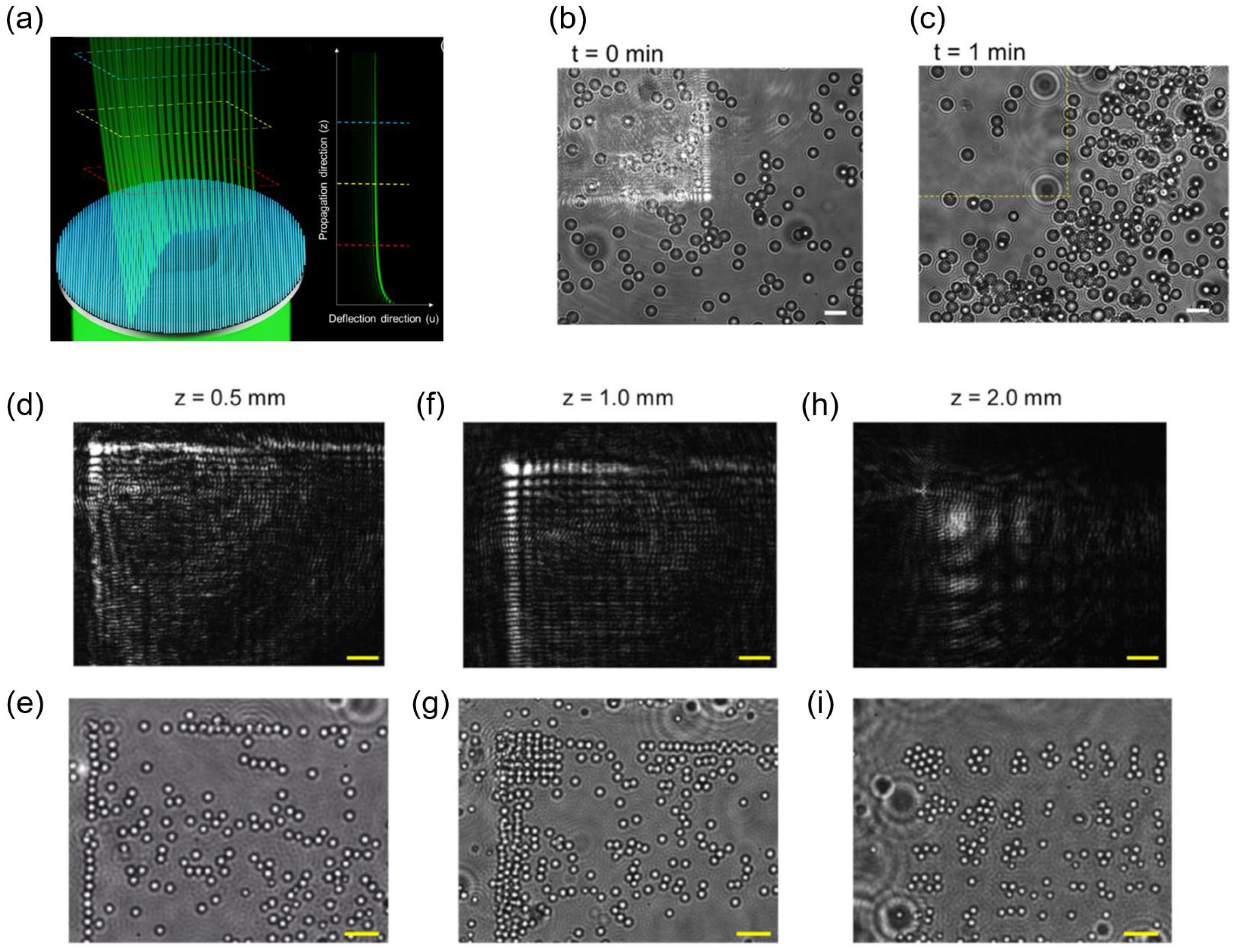
Kuo et al. generated more complex Airy beam OTs with a metasurface device in 2021 [24]. An Airy beam has the characteristic of transverse self-acceleration, allowing the beam to form a bending track, as Figure 8a shows. The unique bending track has outstanding merits in OTs. The nanoparticles can be trapped on the main and side lobes of the Airy beam and travel along the beam. Such a feature can be utilized for the directional transportation of particles. By comparing Figure 8b,c, it is evident that particles were transported to the lower right corner of the area. It can be seen in Figure 8e,g,i that when propagating to a certain distance, the Airy beam forms a regular light lattice, and each point can also trap the particles. These features provide convenience for large-scale sampling and transmission, which expands the application prospects of OTs with metasurfaces.
Structured beams applied in OTs further demonstrate the integration capacity of metasurfaces. Compared with the conventional devices currently used, the metasurface has more freedom in generating beams by its discrete phase adjustment, polarization, and even transmittance. Meanwhile, the metasurface provides a beam modulation ability comparable to that of a traditional spatial light modulator (SLM), with micron size. Considering that an SLM is limited by the power threshold of the incident beam, metasurfaces have higher potential for application in OTs. Concerning the enrichment and development of the manipulation form and prospects for OTs brought by structured beams, such as Airy beams, it could be foreseen that these new structured beams, which have not yet been applied in this context, have great potential for expanding the functions and application space of OTs. The advantages of metasurfaces for generating complex structured beams mean that they represent a powerful tool for achieving these ideas.
3.4. Dynamic Manipulation with Metasurfaces in Optical Tweezers
Compared with traditional OTs, the advantage of the multi-function of the metasurface brings new potential for dynamical manipulation in OTs. The change of incident beams may control the generated light fields due to the anisotropy of the metasurface to the incident beam. The intuitive idea is to achieve focal scanning by titling the incident beams. For a traditional object lens, the outgoing beam will also tilt accordingly when the incident beam is tilted. A similar phenomenon will also occur on metasurface devices. M. X. He led the team to design the metasurface, which converted the transverse intensity distribution of the Gaussian beam into the intensity distribution along the propagation direction, forming a light field distribution sufficient to trap target particles [53]. The oblique scanning of the incident beam can also drive the scanning of the trapped potential well-formed, which further has the potential to manipulate particles dynamically.
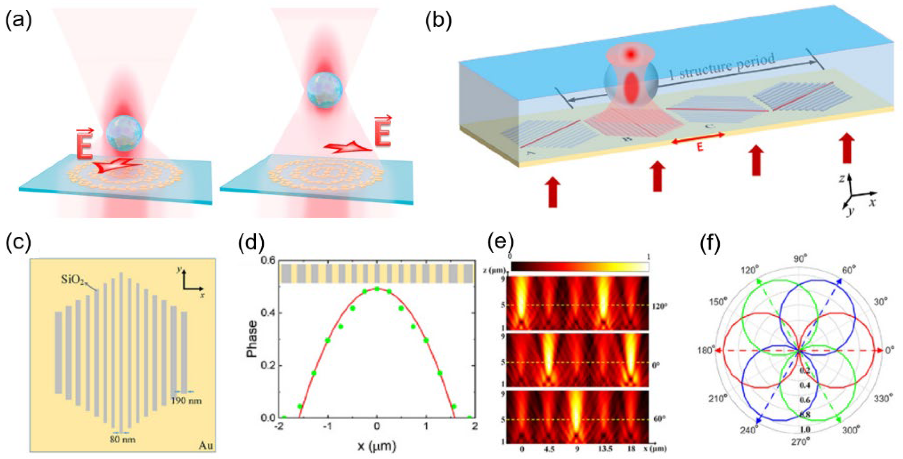
The further idea is to control the light field distribution with the polarization-sensitive metasurface to achieve dynamic manipulation. Markovich et al. designed the metasurface based on the critical operation of creating polarization-sensitive Fresnel zones whose properties predefine the focal spot positions [54], as Figure 9a shows. The metasurface generates the focus points of different focal lengths at the optical axis with the incident linearly polarized beams of different polarization angles. By rotating the polarization direction of the incident beam, the focus position can be changed to realize the dynamic manipulation of particles along the propagation direction. Xu et al. used a similar idea but used a series of metasurface groups to obtain the traverse directional transport of particles [25], which can be seen in Figure 9b. Their metasurface is composed of silica bands in gold film. The silica bands are divided into four groups, and the bands in each group are parallel and form a hexagon. The stripes between different groups form a certain angle to each other and rotate 0, 60, 120, and 180 degrees counterclockwise about the z-axis from left to right, respectively. When the polarization direction is parallel to the silica bands of the metasurfaces, the focus light intensity formed by transmission is the strongest, as Figure 9e,f show. When the polarization direction of the incident light rotates, a directional moving “belt” of hot point can be obtained, and this “hot spot” plays the role of a “conveyor belt” for transporting particles.
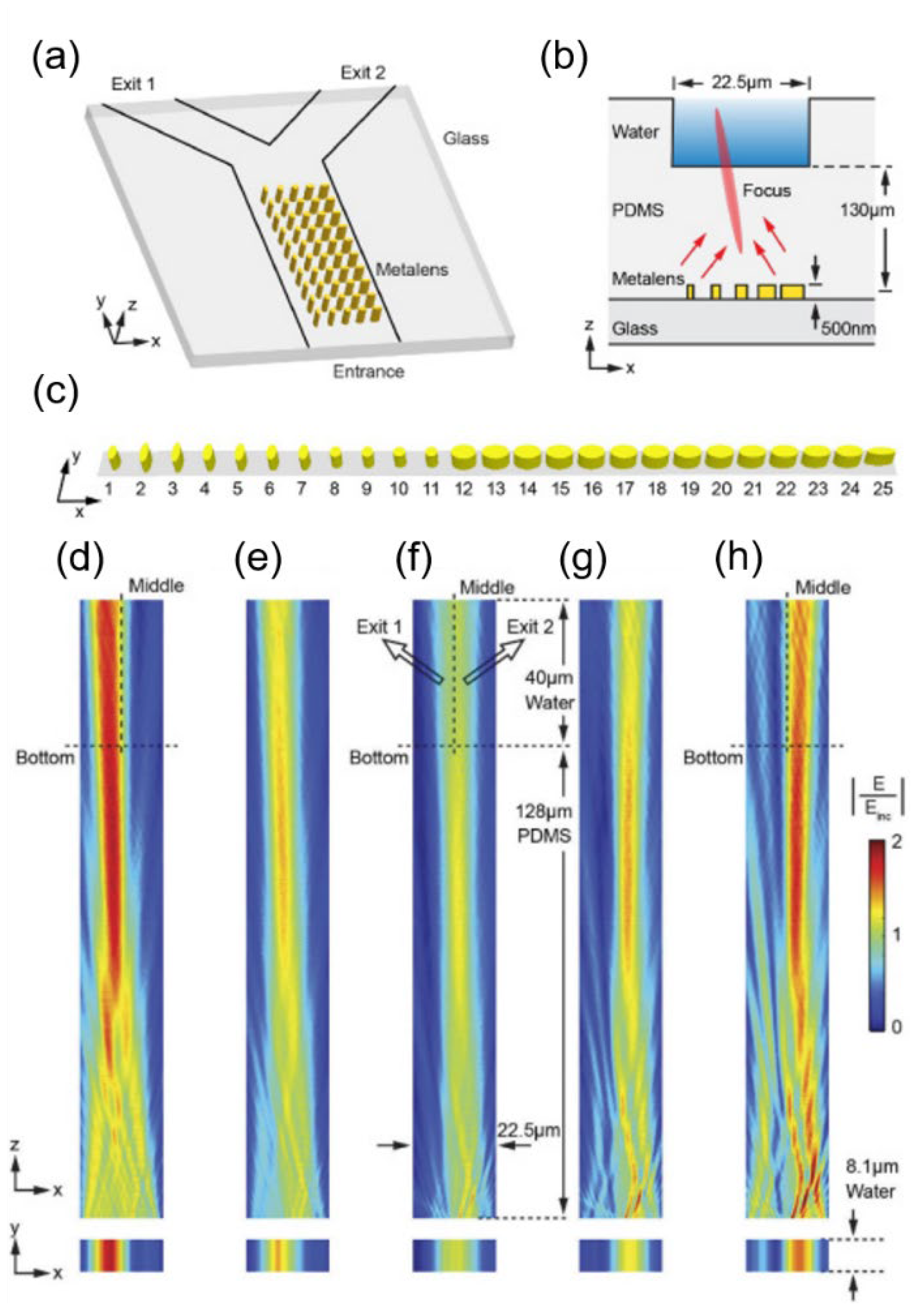
Yin et al. utilized the method of changing the illumination configuration to obtain directional manipulation of the particles [23]. The metasurface was composed of a series of Au nanopillars, covered with a polydimethylsiloxane (PDMS) layer, and placed beneath the microfluidic channel, as shown in Figure 10a,b. Three configurations of illumination were applied. The first two configurations use two coherent, counter-propagating beams with controlled relative phase and strength to illuminate the metasurface. These are the E-antinode (electric field antinode) and the B-antinode (magnetic field antinode), where the magnetic or electric field is zero. The third lighting configuration is a single-beam incident from the PDMS direction. As Figure 10a shows, the microfluidic channel has two outlets. Under three illumination configurations, the metasurface can generate focused light fields pointing to different outlets, as shown in Figure 10d–h. These light fields act like pipes, guiding particles to the corresponding outlets. The illumination configurations can be artificially selected to guide particles to the desired exit. Such directional and adjustable particle transport implies the potential of the metasurface OTs for active optical sorting.
The anisotropy of metasurfaces for incident beams can produce different modulation effects when incident beams change, giving metasurfaces the advantage of multi-function. This merit is revealed by OTs that use a single metasurface to achieve dynamic manipulation perfectly. The metasurface applied in OTs can expand the degree of the freedom of beam control, and such a feature enables expansion of the freedom of dynamic manipulation. This characteristic greatly expands OTs’ simplicity and application prospects in dynamic manipulation. Dynamic manipulation based on metasurfaces can also be applied to active optical sorting. A simple change of the incident beam can realize the transfer of hot spots in the light field, allowing free control of target particles. Such features mean that OTs with metasurfaces have great potential for precise dynamic manipulation.
3.5. Particle Sorting in Optical Tweezers with Metasurfaces
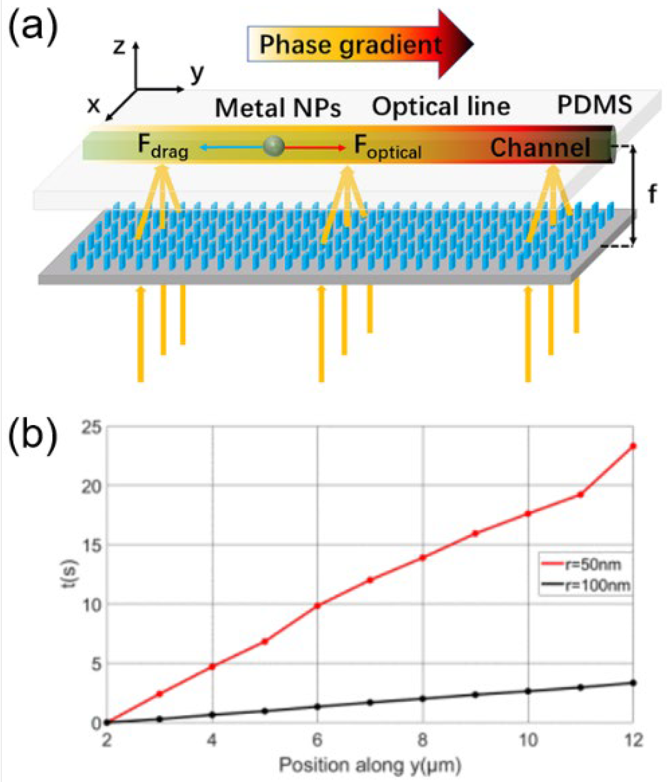
Passive sorting through the different motion states of different particles is a simpler and more feasible approach than performing artificially active sorting through the dynamic manipulation of OTs with metasurfaces. In dynamic manipulation, it is natural to find that particles’ size and other parameters may influence their movement states. Z. Shen et al. developed a particle sorting method through a numerical study [55]. The structure of the metasurface is illustrated in Figure 11a. The metasurface worked as a cylindrical lens with a phase gradient. Through simulation and theoretical calculation, they concluded that particles could be trapped at the striped focal spot. The force caused by the phase gradient drove the particles to move directionally. Particles of different radii moved at different velocities, as shown in Figure 11b. Based on such a feature, particles can be sorted according to their sizes after traveling for some distance.
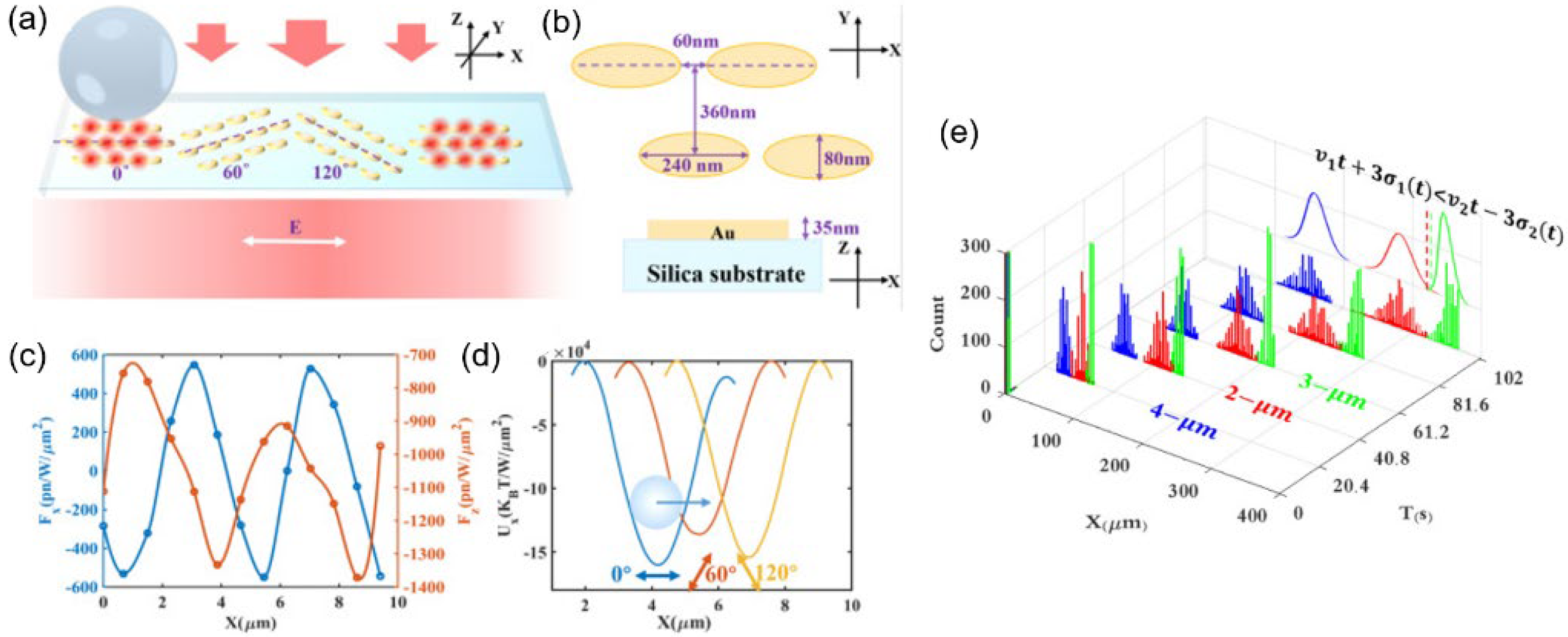
Zhang et al. adopted the methods of the “optical conveyor belt” to transmit particles [26], similar to the idea of Xu’s work in Section 3.4. The SiO2 bands embedded in the gold film were replaced by oval Au nano blocks arranged in stripes on the SiO2 substrate. Figure 12a,b shows that a cycle comprises three metasurfaces rotating 0, 120, and 240 degrees, respectively. With the rotating incident linearly polarized beam, the “hot spot” moves directionally and the particles are transmitted on the “conveyor belt”. The nanoparticles transmitted by the belt travel at different velocities and, after moving several cycles, particles of different sizes can be separated. Different colors in Figure 12e represent particles with different radii. The mixed particles have been separated.
Optical sorting with the OTs with metasurfaces can be divided into two aspects, active sorting, and passive sorting. The active method involves artificially changing the incident light to actively control the movement of particles with the help of the metasurface’s excellent dynamic optical modulation ability. The passive method uses particle motion speed differences during transmission to distinguish particles of different sizes. Compared with the active method, the passive approach is more convenient for sorting. It is necessary to distinguish the movement states of different particles in advance. The OTs with metasurface utilized for passive optical particle sorting mentioned in this section were based on the forms of dynamic optical manipulation mentioned in Section 3.4. Optical sorting could be considered as a further development of dynamic manipulation and further indicates the advantages of multi-functionality of metasurfaces in OTs. This type of optical particle sorting discards the process of coloring, resolving, and charging required in the current common sorting methods. Simply, the movement of particles can separate the particles according to size. In addition, particles with similar refractive indexes can be sorted with this method, which expands the application of optical sorting and improves the degree of freedom of sorting. Meanwhile, planarized metasurfaces can be easily applied to the chip to reduce the system’s volume. In addition, the planarization of the metasurface allows these optical tweezers to be easily combined with other devices on chip.
3.6. Near-Field Optical Tweezers with Metasurfaces
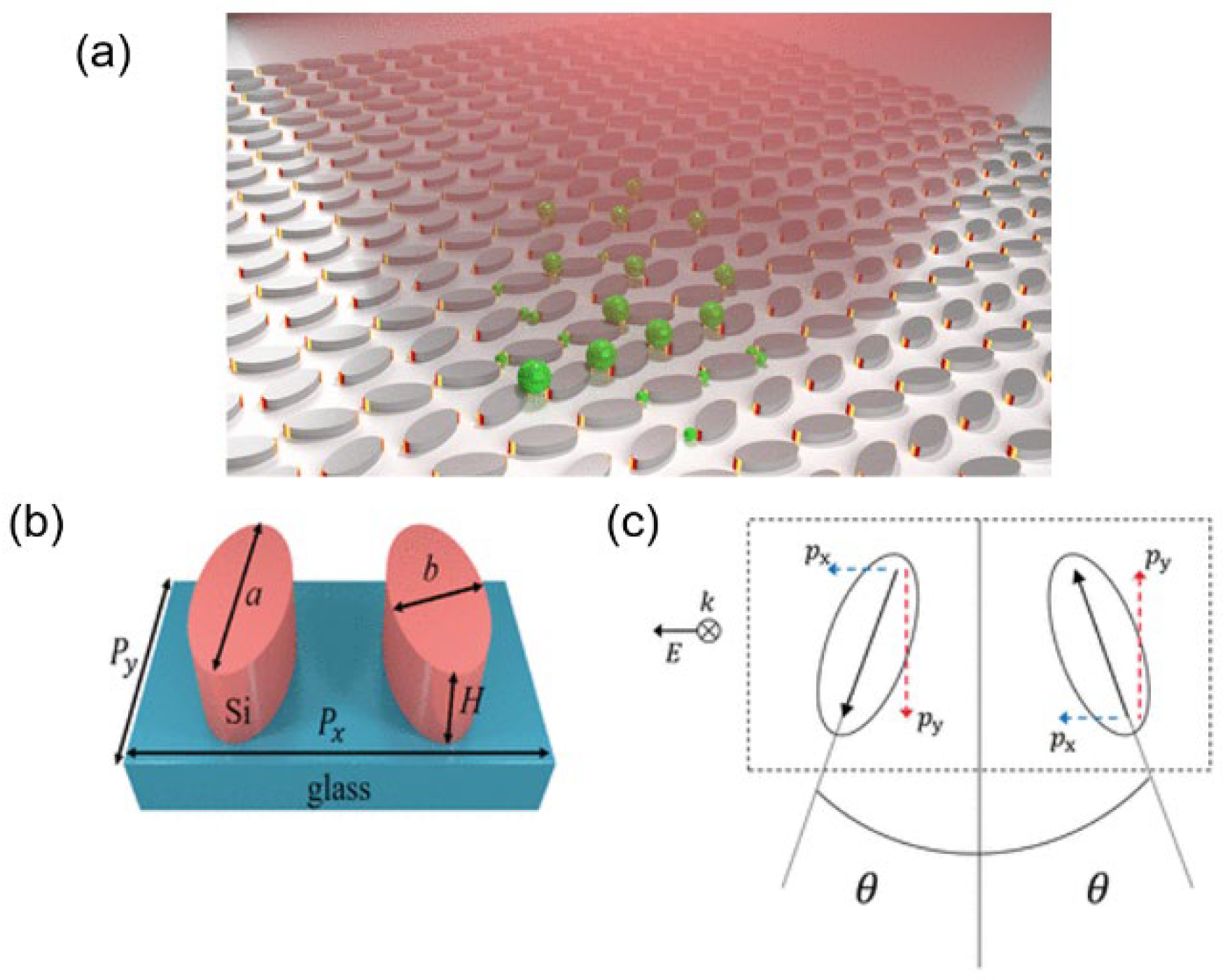
The OTs with metasurfaces mentioned above can be classified as far-field OTs. For a far-field OT, the beam converges to form the required light field distribution at a position with a distance from the surface of the metasurface and then manipulates the target particles. In this section, we introduce OTs with metasurfaces that trap particles on the surface of the metasurface. This kind of OT with metasurface can be called near-field OTs. A typical method utilized by near-field OTs with metasurfaces is to trap the particles at the hot spots between the metasurface cells. For example, Yang et al. developed OTs with quasi-bound states in the continuum (quasi-BICs) [27]. Quasi-BICs can achieve high quality factor (Q factor) resonances as well as high field enhancement. The metasurface comprised oval Si nano blocks on the silica substrates, as illustrated in Figure 13a–c. With the help of a quasi-BICs system, the field enhancements were observed between cells. SiO2 nanoparticles are shown trapped at the series of focal spots as green spheres in Figure 13a.
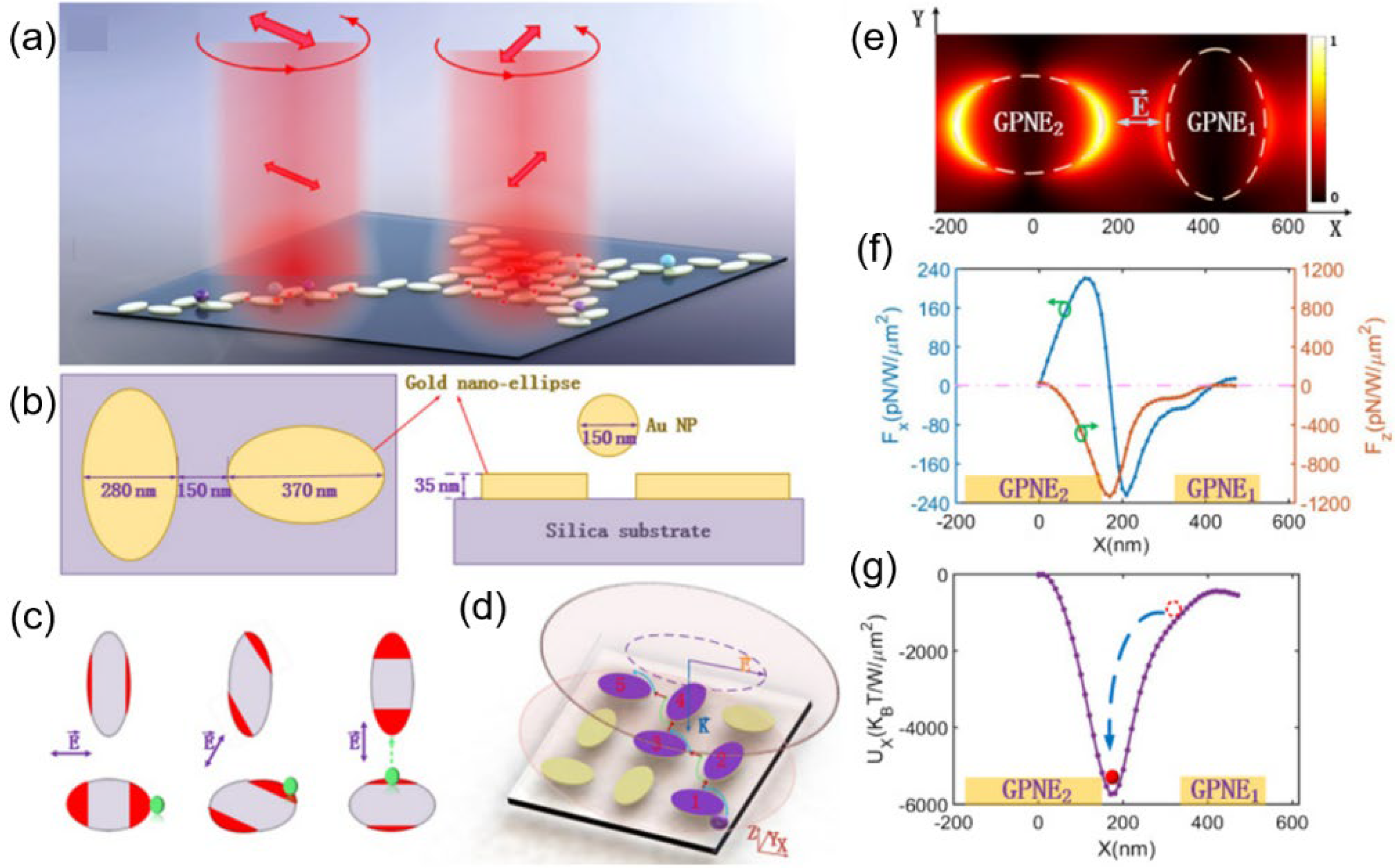
Jiang et al. designed a plasmonic nano-ellipse metasurface composed of oval gold nano blocks on a silica substrate [56]. Nano blocks were arranged on rectangular grid points, with the long axes of any adjacent nano blocks perpendicular to each other, as shown in Figure 14a,b. The linearly polarized beam was incident from the direction of the nano blocks. By rotating the polarization angle, it is possible to turn on/off the hot spots between adjacent nano blocks, as Figure 14c shows. The change of the hot spots then conveys the trapped particles on the nano blocks due to the rotation of the incident beam, as illustrated in Figure 14d.
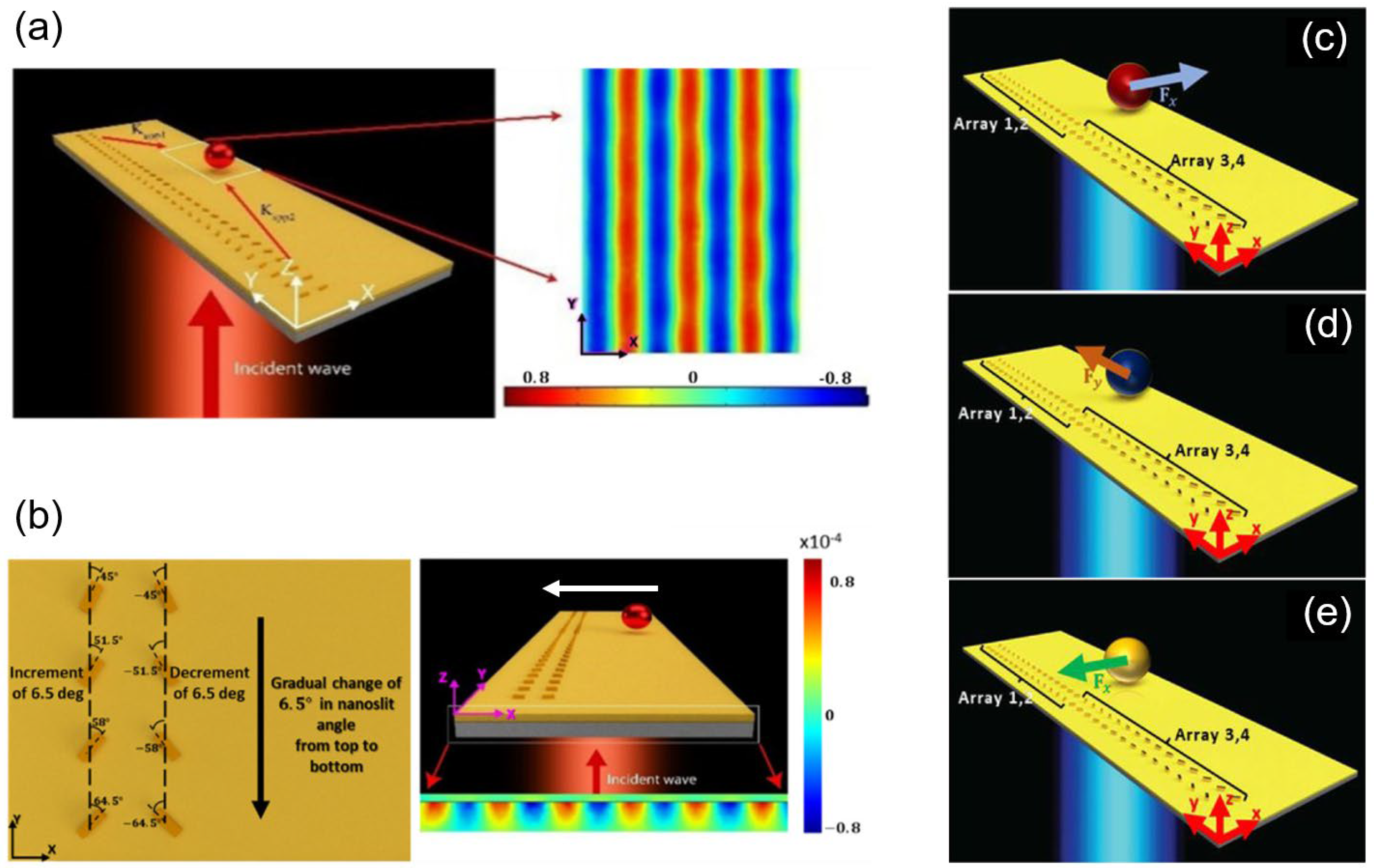
Another method adopted is to generate SPPs with the help of the metasurface and obtain optical manipulation with the SPPs. Rahim et al. [57] and Safkat et al. [58] followed similar ideas, both utilizing two groups of V-shaped metasurfaces. When the beam was incident, SPPs generated by the two metasurfaces were coherent, and the interference field was formed over the substrate. Hence, the central region of the substrate had a continuous distribution of electric field, as Figure 15a shows. The interference field can exert optical forces on particles on the substrate’s surface and directionally manipulate them. Rahim’s work successfully exerted intriguing optical pulling forces on particles regardless of their materials, as the arrow in Figure 15b shows. According to their calculation, particles with sufficient radii were subject to the pulling force regardless of their material. Meanwhile, it is worth noting that Safkat drew interesting conclusions for smaller particles (with radii of around 200 nm) under similar configurations. For particles of different materials (dielectric, plasmonic, or chiral objects), the direction of the optical forces pointed to different paths through numerical study, as shown in Figure 15c–e. These results indicate the system’s potential for being applied to optical sorting.
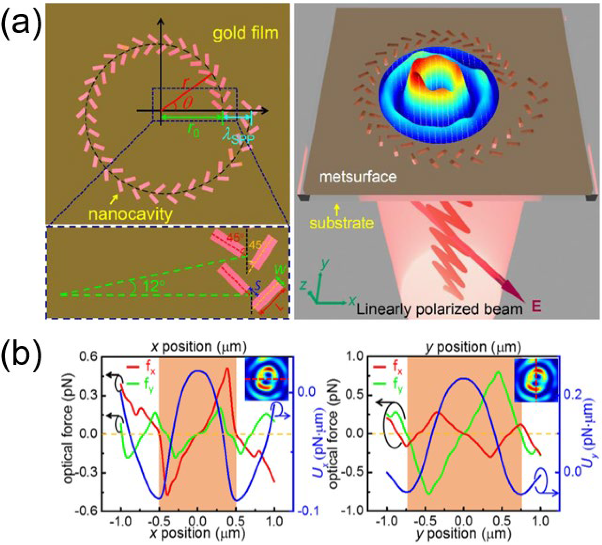
In addition to the coherence of SPPs from two sets of metasurfaces, the characteristic of metasurface cells being able to arrange independently at will provides a new possibility for near-field optical manipulation. For example, Yang et al. designed metasurfaces with cells arranged as a right-hand Archimedes’ spiral on a golden film [59]. Each cell was composed of two V-shaped nanocavities, as Figure 16a shows. When the linearly polarized beam was incident, the SPP formed as a halo, and the particles could be trapped at the hot halo. It should be noted that the specially arranged nanocavities introduced the OAM into the incident linearly polarized beam, enabling the system to rotate the trapped particles without the help of OVs. As Figure 16b shows, particles were trapped at the halo, and the optical forces drove them to rotate along the halo.
Near-field OTs trap targets on their surface. With the help of delicate metasurface devices, the OT systems become smaller and more planar. This characteristic further expands the application scope of OTs with metasurfaces on chips. Moreover, metasurfaces in near-field OTs show a good field enhancement effect (typically with the help of SPP or quasi-BIC). This feature enhances the trapping depth of particles and tempers the requirements for light source power without weakening the trapping effect, making the near-field OTs with metasurfaces more widely used. By adjusting the metasurfaces or the incident beams, these near-field OTs with metasurfaces can accurately locate the potential well’s exact position and exhibit more flexible trapping and manipulation capabilities. The OTs mentioned above have not entirely overcome the shortcomings of the traditional evanescent wave near-field OTs; for example, the evanescent wave decays rapidly in a short distance and cannot manipulate the target particles at a longer distance. However, such innovations have provided a new degree of freedom for the optical field control of near-field OTs, providing near-field OTs with broad development prospects.
4. Conclusions and Outlook
In this review, we introduced the current development of OTs with metasurfaces. First, metasurfaces can effectively replace traditional objective lenses in OT systems. Metasurface devices greatly reduce the volume of devices and improve the flexibility of OTs. Although there are still some defects, the application of metasurfaces brings tremendous potential for OTs. Second, a single metasurface can integrate the phases of various devices, and even various functions, further improving the miniaturization of devices. Meanwhile, this feature also reduces the requirements for the accuracy of optical path assembly and optical axis alignment, improving the system’s reliability. The merits of metasurfaces for the generation of complex structured beams make it easier to use OTs with metasurfaces to apply structured beams. Third, using a single metasurface, the dynamic manipulation of particles in the beam can be obtained through simple modulation of the incident beam. Metasurfaces provide more freedom for optical manipulation in OTs. The flexible and simple operation also makes active particle sorting possible. With the development of dynamic manipulation, optical conveyor belts have also been obtained. It is also possible to sort particles passively according to their movement rates without artificial control, demonstrating a new and more straightforward way of sorting particles without losing accuracy. Finally, metasurfaces play a role in near-field OTs. The metasurface can help accurately locate the trapping position, improve the local field strength to improve the trapping ability, or modulate the light field distribution to expand the manipulation ability. In general, the application of metasurfaces in OTs has brought new characteristics and advantages for OTs. These advantages can be attributed to four features of metasurfaces: miniaturization, integration, multi-function, and planarization.
- First, metasurface devices effectively reduce the volume of the OTs, making the OTs more flexible. The connection of the production process of the metasurface and the chip also means that OTs with metasurfaces have unique advantages on chips. These features reflect the advantages of the miniaturization of the metasurface.
- Second, multiple devices can be integrated into a single ultra-thin metasurface, and the system’s compactness is further improved. Meanwhile, metasurfaces have performed excellently in the generation of complex structured beams. This makes the application of metasurface in OTs promising. The merit of integration is clearly shown.
- Third, metasurfaces expand the freedom of light field control, making dynamic manipulation more flexible. Active or passive optical sorting with the help of OTs with metasurfaces is also uniquely improved compared with the current methods. Owing to the multi-function of the metasurface, OTs with metasurfaces have developed such applications.
- Fourth, OTs with metasurfaces have great advantages in the lab-on-chip, which can be easily combined with various devices. The free arrangement of metasurfaces can make near-field OTs distribution more controllable and achieve more flexible manipulation. The planarization of the metasurface endows the OTs with these properties.
Of course, when using metasurfaces, it is necessary to consider some of their shortcomings. For example, the efficiency is lower than that of traditional objective lenses, and the Nyquist sampling theorem limits the width of the phase fringes displayed on the metasurfaces. However, for many applications, the merits of metasurfaces outweigh such flaws. Novel metasurfaces, with their special advantages in beam modulation, are bound to contribute to great achievements in developing OTs in the future.
Author Contributions
Investigation, X.H.; writing—original draft preparation, X.H.; writing—review and editing, Z.S.; supervision, Z.S.; funding acquisition, Z.S. All authors have read and agreed to the published version of the manuscript.
Funding
This research was funded by National Natural Science Foundation of China (61805119, 62275122), Natural Science Foundation of Jiangsu Province (BK20180469, BK20180468), and Fundamental Research Funds for the Central Universities (30919011275).
Institutional Review Board Statement
Not applicable.
Informed Consent Statement
Not applicable.
Data Availability Statement
Data sharing not applicable.
Conflicts of Interest
The authors declare no conflict of interest.
References
- Paul, N.K.; Gomez-Diaz, J.S. Tunable optical traps over nonreciprocal surfaces. Opt. Express 2022, 30, 46344–46356. [Google Scholar] [CrossRef] [PubMed]
- Liu, P.Q.; Paul, P. Graphene nanoribbon plasmonic conveyor belt network for optical trapping and transportation of nanoparticles. ACS Photonics 2020, 7, 5456–5466. [Google Scholar] [CrossRef]
- Xiao, G.Z.; Kuang, T.F.; Luo, B.; Xiong, W.; Han, X.; Chen, X.L.; Luo, H. Coupling between axial and radial motions of microscopic particle trapped in the intracavity optical tweezers. Opt. Express 2019, 27, 36653–36661. [Google Scholar] [CrossRef]
- Liang, Y.; Liang, G.; Xiang, Y.X.; Lamstein, J.; Gautam, R.; Bezryadina, A.; Chen, Z.G. Manipulation and assessment of human red blood cells with tunable “tug-of-war” optical tweezers. Phys. Rev. Appl. 2019, 12, 064060. [Google Scholar] [CrossRef]
- Ashkin, A. Acceleration and trapping of particles by radiation pressure. Phys. Rev. Lett. 1970, 24, 156–159. [Google Scholar] [CrossRef]
- Ashkin, A.; Dziedzic, J.M.; Bjorkholm, J.E.; Chu, S. Observation of a single-beam gradient force optical trap for dielectric particles. Opt. Lett. 1986, 11, 288–290. [Google Scholar] [CrossRef] [PubMed]
- Koch, M.; Rohrbach, A. Object-adapted optical trapping and shape-tracking of energy-switching helical bacteria. Nat. Photonics 2012, 6, 680–686. [Google Scholar] [CrossRef]
- Pang, Y.; Song, H.; Kim, J.H.; Hou, X.; Cheng, W. Optical trapping of individual human immunodeficiency viruses in culture fluid reveals heterogeneity with single-molecule resolution. Nat. Nanotechnol. 2014, 9, 624–630. [Google Scholar] [CrossRef]
- Liu, L.R.; Hood, J.D.; Yu, Y.; Zhang, J.T.; Hutzler, N.R.; Rosenband, T.; Ni, K.-K. Building one molecule from a reservoir of two atoms. Science 2018, 360, 900–903. [Google Scholar] [CrossRef]
- Chan, J.; Alegre, T.P.; Safavi-Naeini, A.H.; Hill, J.T.; Krause, A.; Groblacher, S.; Aspelmeyer, M.; Painter, O. Laser cooling of a nanomechanical oscillator into its quantum ground state. Nature 2011, 478, 89–92. [Google Scholar] [CrossRef]
- Righini, M.; Volpe, G.; Girard, C.; Petrov, D.; Quidant, R. Surface plasmon optical tweezers: Tunable optical manipulation in the femtonewton range. Phys. Rev. Lett. 2008, 100, 186804. [Google Scholar] [CrossRef] [PubMed]
- Zensen, C.; Villadsen, N.; Winterer, F.; Keiding, S.R.; Lohmuller, T. Pushing nanoparticles with light—A femtonewton resolved measurement of optical scattering forces. APL Photonics 2016, 1, 26102. [Google Scholar] [CrossRef]
- Dogariu, A.; Sukhov, S.; Sáenz, J.J. Optically induced ‘negative forces’. Nat. Photonics 2012, 7, 24–27. [Google Scholar] [CrossRef]
- Ahn, J.; Xu, Z.J.; Bang, J.; Deng, Y.H.; Hoang, T.M.; Han, Q.K.; Ma, R.M.; Li, T.C. Optically levitated nanodumbbell torsion balance and GHz nanomechanical rotor. Phys. Rev. Lett. 2018, 121, 033603. [Google Scholar] [CrossRef]
- Shen, Z.; Xiang, Z.Y.; Wang, Z.Y.; Shen, Y.C.; Zhang, B.F. Optical spanner for nanoparticle rotation with focused optical vortex generated through a Pancharatnam-Berry phase metalens. Appl. Opt. 2021, 60, 4820–4826. [Google Scholar] [CrossRef]
- Chen, M.; Huang, S.; Liu, X.; Chen, Y.; Shao, W. Optical trapping and rotating of micro-particles using the circular Airy vortex beams. Appl. Phys. B 2019, 125, 184. [Google Scholar] [CrossRef]
- Otte, E.; Tekce, K.; Denz, C. Tailored intensity landscapes by tight focusing of singular vector beams. Opt. Express 2017, 25, 20194–20201. [Google Scholar] [CrossRef] [PubMed]
- Shen, Z.; Liu, H.C.; Zhang, S.; Shen, Y.C.; Zhang, B.F.; Luo, S.Y. Optical manipulation of Rayleigh particles by metalenses-a numerical study. Appl. Opt. 2019, 58, 5794–5799. [Google Scholar] [CrossRef]
- Xiang, Z.Y.; Shen, Z.; Shen, Y.C. Quasi-perfect vortices generated by Pancharatnam-Berry phase metasurfaces for optical spanners and OAM communication. Sci. Rep. 2022, 12, 1053. [Google Scholar] [CrossRef]
- Wen, J.; Chen, L.; Chen, X.; Kanwal, S.; Zhang, L.H.; Zhuang, S.L.; Zhang, D.W.; Lei, D.Y. Use of dielectric metasurfaces to generate deep-subwavelength nondiffractive Bessel-like beams with arbitrary trajectories and ultralarge deflection. Laser Photonics Rev. 2021, 15, 2000487. [Google Scholar] [CrossRef]
- Suwannasopon, S.; Meyer, F.; Schlickriede, C.; Chaisakul, P.; T-Thienprasert, J.; Limtrakul, J.; Zentgraf, T.; Chattham, N. Miniaturized metalens based optical tweezers on liquid crystal droplets for lab-on-a-chip optical motors. Crystals 2019, 9, 515. [Google Scholar] [CrossRef]
- Chantakit, T.; Schlickriede, C.; Sain, B.; Meyer, F.; Weiss, T.; Chattham, N.; Zentgraf, T. All-dielectric silicon metalens for two-dimensiona particle manipulation in optical tweezers. Photonics Res. 2020, 8, 1435–1440. [Google Scholar] [CrossRef]
- Yin, S.Q.; He, F.; Kubo, W.; Wang, Q.; Frame, J.; Green, N.G.; Fang, X. Coherently tunable metalens tweezers for optofluidic particle routing. Opt Express 2020, 28, 38949–38959. [Google Scholar] [CrossRef] [PubMed]
- Kuo, H.Y.; Vyas, S.; Chu, C.H.; Chen, M.K.; Shi, X.; Misawa, H.; Lu, Y.J.; Luo, Y.; Tsai, D.P. Cubic-phase metasurface for three-dimensional optical manipulation. Nanomaterials 2021, 11, 1730. [Google Scholar] [CrossRef]
- Xu, F.; Liu, Y.; Zhang, C.; Jiang, M.; Zhang, J.H.; Wang, G.H.; Xu, F.; Lu, Y.Q. Optically levitated conveyor belt based on polarization-dependent metasurface lens arrays. Opt. Lett. 2022, 47, 2194–2197. [Google Scholar] [CrossRef]
- Zhang, C.; Jiang, M.; Chang, Y.; Liu, Y.; Wang, G.H.; Xu, F.; Lu, Y.Q. Optical conveyor belt based on a plasmonic metasurface with polarization dependent hot spot arrays. Opt. Lett. 2021, 46, 1522–1525. [Google Scholar] [CrossRef]
- Yang, S.; Hong, C.C.A.; Jiang, Y.X.; Ndukaife, J.C. Nanoparticle trapping in a quasi-BIC system. ACS Photonics 2021, 8, 1961–1971. [Google Scholar] [CrossRef]
- Peng, J.; Jia, S.; Zhang, C.; Wang, S. Optical force and torque on small particles induced by polarization singularities. Opt. Express 2022, 30, 16489–16498. [Google Scholar] [CrossRef]
- Nieto-Vesperinas, M.; Saenz, J.J.; Gomez-Medina, R.; Chantada, L. Optical forces on small magnetodielectric particles. Opt. Express 2010, 18, 11428–11443. [Google Scholar] [CrossRef]
- Pfeiffer, C.; Grbic, A. Generating stable tractor beams with dielectric metasurfaces. Phys. Rev. B 2015, 91, 115408. [Google Scholar] [CrossRef]
- Liou, K.-N. A complementary theory of light scattering by homogeneous spheres. Appl. Math. Comput. 1977, 3, 331–358. [Google Scholar] [CrossRef]
- Gouesbet, G.; De Angelis, V.S.; Ambrosio, L.A. Optical forces and optical force categorizations on small magnetodielectric particles in the framework of generalized Lorenz-Mie theory. J. Quant. Spectrosc. Radiat. Transf. 2022, 279, 108046. [Google Scholar] [CrossRef]
- Mitri, F.G.; Li, R.X.; Guo, L.X.; Ding, C.Y. Optical tractor Bessel polarized beams. J. Quant. Spectrosc. Radiat. Transf. 2017, 187, 97–115. [Google Scholar] [CrossRef]
- Liu, W.L.; McLeod, E. Accuracy of the skin depth correction for metallic nanoparticle polarizability. J. Phys. Chem. C 2019, 123, 13009–13014. [Google Scholar] [CrossRef]
- Beth, A.R. Mechanical detection and measurement of the angular momentum of light. Phys. Rev. 1936, 50, 115–125. [Google Scholar] [CrossRef]
- Chang, S.; Lee, S.S. Optical torque exerted on a homogeneous sphere levitated in the circularly polarized fundamental-mode laser beam. J. Opt. Soc. Am. B 1985, 2, 1853–1860. [Google Scholar] [CrossRef]
- Allen, L.; Beijersbergen, M.W.; Spreeuw, R.J.; Woerdman, J.P. Orbital angular momentum of light and the transformation of Laguerre-Gaussian laser modes. Phys. Rev. A 1992, 45, 8185–8189. [Google Scholar] [CrossRef]
- Zhu, Q.; Li, N.; Su, H.M.; Li, W.Q.; Hu, H.Z. A review of optically induced rotation. Front. Inform. Tech. El. 2022, 23, 171–185. [Google Scholar] [CrossRef]
- Friese, M.E.J.; Nieminen, T.A.; Heckenberg, N.R.; Rubinsztein-Dunlop, H. Optical torque controlled by elliptical polarization. Opt. Lett. 1998, 23, 1–3. [Google Scholar] [CrossRef]
- Nieminen, T.A.; Rubinsztein-Dunlop, H.; Heckenberg, N.R. Calculation and optical measurement of laser trapping forces on non-spherical particles. J. Quant. Spectrosc. Radiat. Transf. 2001, 70, 627–637. [Google Scholar] [CrossRef]
- Nieminen, T.A.; Heckenberg, N.R.; Rubinsztein-Dunlop, H. Optical measurement of microscopic torques. J. Mod. Opt. 2001, 48, 405–413. [Google Scholar] [CrossRef]
- Nieminen, T.A.; Parkin, S.; Heckenberg, N.R.; Rubinsztein-Dunlop, H. Optical torque and symmetry. Opt. Trapp. Opt. Micromanipulation 2004, 5514, 254–263. [Google Scholar]
- Bonin, K.D.; Kourmanov, B. Light torque nanocontrol, nanomotors and nanorockers. Opt. Express 2002, 10, 984–989. [Google Scholar] [CrossRef]
- Sheu, F.-W.; Lan, T.-K.; Lin, Y.-C.; Chen, S.; Ay, C. Stable trapping and manually controlled rotation of an asymmetric or birefringent microparticle using dual-mode split-beam optical tweezers. Opt. Express 2010, 18, 14724–14730. [Google Scholar] [CrossRef]
- Shen, K.H.; Duan, Y.; Ju, P.; Xu, Z.J.; Chen, X.; Zhang, L.D.; Ahn, J.; Ni, X.J.; Li, T.C. On-chip optical levitation with a metalens in vacuum. Optica 2021, 8, 1359–1362. [Google Scholar] [CrossRef]
- Khorasaninejad, M.; Chen, W.T.; Devlin, R.C.; Oh, J.; Zhu, A.Y.; Capasso, F. Metalenses at visible wavelengths: Diffraction-limited focusing and subwavelength resolution imaging. Science 2016, 352, 1190–1194. [Google Scholar] [CrossRef]
- Sun, P.; Zhang, M.; Dong, F.; Feng, L.; Chu, W. Broadband achromatic polarization insensitive metalens over 950 nm bandwidth in the visible and near-infrared. Chin. Opt. Lett. 2022, 20, 013601. [Google Scholar] [CrossRef]
- Ma, Y.B.; Rui, G.H.; Gu, B.; Cui, Y.P. Trapping and manipulation of nanoparticles using multifocal optical vortex metalens. Sci. Rep. 2017, 7, 14611. [Google Scholar] [CrossRef]
- Li, T.Y.; Xu, X.H.; Fu, B.Y.; Wang, S.M.; Li, B.J.; Wang, Z.L.; Zhu, S.N. Integrating the optical tweezers and spanner onto an individual single-layer metasurface. Photonics Res. 2021, 9, 1062–1068. [Google Scholar] [CrossRef]
- Li, X.Y.; Zhou, Y.; Ge, S.Y.; Wang, G.X.; Li, S.Q.; Liu, Z.L.; Li, X.; Zhao, W.; Yao, B.L.; Zhang, W.F. Experimental demonstration of optical trapping and manipulation with multifunctional metasurface. Opt. Lett. 2022, 47, 977–980. [Google Scholar] [CrossRef]
- Wang, X.Y.; Dai, Y.M.; Zhang, Y.Q.; Min, C.J.; Yuan, X.C. Plasmonic manipulation of targeted metallic particles by polarization-sensitive metalens. ACS Photonics 2018, 5, 2945–2950. [Google Scholar] [CrossRef]
- Zhu, J.L.; Jin, R.C.; Tang, L.L.; Dong, Z.G.; Li, J.Q.; Wang, J. Multidimensional trapping by dual-focusing cylindrical vector beams with all-silicon metalens. Photonics Res. 2022, 10, 1162–1169. [Google Scholar] [CrossRef]
- He, M.X.; Guo, Y.H.; Li, C.S.; Tong, X.; Liu, H.A.; Li, G.F.; Zhang, L. Metasurface-based wide-angle beam steering for optical trapping. IEEE Access 2020, 8, 37275–37280. [Google Scholar] [CrossRef]
- Markovich, H.; Shishkin, I.I.; Hendler, N.; Ginzburg, P. Optical manipulation along an optical axis with a polarization sensitive meta-lens. Nano Lett. 2018, 18, 5024–5029. [Google Scholar] [CrossRef] [PubMed]
- Shen, Z.; Wang, Z.Y.; Liu, H.C.; Shen, Y.C. Optical trapping and separation of metal nanoparticles by cylindrical metalenses with phase gradients. IEEE Photonics J. 2020, 12, 4600810. [Google Scholar] [CrossRef]
- Jiang, M.; Wang, G.H.; Xu, W.H.; Ji, W.B.; Zou, N.M.; Ho, H.P.; Zhang, X.P. Two-dimensional arbitrary nano-manipulation on a plasmonic metasurface. Opt. Lett. 2018, 43, 1602–1605. [Google Scholar] [CrossRef]
- Rahim, M.; Mahdy, M.R.C.; Das, S.C.; Sunny, M.M. A generic metasurface for the optical pulling of dielectric or plasmonic or chiral Mie objects. Opt. Commun. 2022, 508, 127679. [Google Scholar] [CrossRef]
- Safkat, K.; Rahim, M.; Mahdy, M.R.C. Optical sorting of a plasmonic or dielectric or chiral Mie object using a single metasurface. Ann. Phys. 2022, 534, 210042. [Google Scholar] [CrossRef]
- Yang, Y.; Huang, S.Y. Trapping and rotation of microparticles using a metasurface exciting by linearly polarized beam. Nanomater. Nanotechnol. 2021, 11, 73–81. [Google Scholar] [CrossRef]
Figure 1.
(a,b) The structure diagram of the metasurface and the cell. (c) The focal point generated with the designed metasurface. (d) Schematic diagram of optical forces on particles at different positions in the light field. It can be seen that the optical forces point to the beam focus. Adapted from ref. [18]. © 2019 Optica Publishing Group. Users may use, reuse, and build upon the article, or use the article for text or data mining, so long as such uses are for non-commercial purposes and appropriate attribution is maintained. All other rights are reserved.

Figure 2.
(a) The local schematic diagram of the metasurface. (b) The schematic diagram of the metasurface and particles in the experiment. (c) Experimental results of particle trapping. The black arrow represents the flow direction of the background liquid. From left to right, it can be seen that the particles were trapped at the focal point. Adapted from ref. [21].

Figure 3.
(a,b) The metasurface’s overall and local schematic diagram. (c) The schematic diagram of particle movement between potential wells generated by metasurface and traditional objective lens. Adapted from ref. [45]. © 2021 Optica Publishing Group. (d,e) The overall and local schematic diagram of the metasurface. (f) The nanoparticles are arranged as letters. Adapted from ref. [22]. © 2020 Optica Publishing Group. Users may use, reuse, and build upon the article, or use the article for text or data mining, so long as such uses are for non-commercial purposes and appropriate attribution is maintained. All other rights are reserved.

Figure 4.
(a) The overall and local schematic diagram of the metasurface OT. (b) The particle rotates along the halo. Adapted from ref. [22]. © 2020 Optica Publishing Group. (c) The structure diagram of metasurface assembly and unit. (d) The halo is generated with the metasurface at the focal plane. The arrows indicate the time-averaged Poynting vectors, and the particles trapped at the halo rotate along them. Adapted from ref. [15]. © 2021 Optica Publishing Group. Users may use, reuse, and build upon the article, or use the article for text or data mining, so long as such uses are for non-commercial purposes and appropriate attribution is maintained. All other rights are reserved.

Figure 5.
(a,b) The structure diagram of the combined OT and OS system and the diagram of the cell of the metasurface. (c) Beams generated with the metasurfaces. Adapted from ref. [49]. © 2021 Optica Publishing Group. (d) The structure diagram of the multipurpose metasurface. (e) The trapping and manipulating effect of the OT. (i) The OT traps and manipulates the SiO2 sphere with the light spot when LCP is incident. The blue sphere is the target sphere which moves in the direction of the white arrow. The black sphere is a fixed reference. (ii) The CaCO3 particle spins counterclockwise when the light spot traps it. (iii) Eight SiO2 spheres are trapped at the halo generated with RCP. The blue mark indicates their clockwise rotation along the halo. (iv) The CaCO3 particle spins when it rotates clockwise along the halo. Adapted from ref. [50]. © 2022 Optica Publishing Group. Users may use, reuse, and build upon the article, or use the article for text or data mining, so long as such uses are for non-commercial purposes and appropriate attribution is maintained. All other rights are reserved.

Figure 6.
(a,b) The diagram of the metasurface and the trapping of the particle. (c,d) The results of the experiment. Curves of different colors represent particles that should be excluded, and the red curves in the center represent the trapped target particle. Reprinted (adapted) with permission from ref. [51] ACS Photonics 2018, 5, 7, 2945–2950. Copyright 2018 American Chemical Society.

Figure 7.
(a) The diagram of the metasurface generating the structured beams. The blue and pink regions on the metasurface correspond to focal spots with azimuthal and radial polarizations, respectively. (b,c) The results of the beams generated with the metasurface. It can be seen that the radial and angular polarized beams formed a focus, respectively. (d–f) The optical forces exerted on the particle in the light field. Adapted from ref. [52]. © 2022 Optica Publishing Group. Users may use, reuse, and build upon the article, or use the article for text or data mining, so long as such uses are for non-commercial purposes and appropriate attribution is maintained. All other rights are reserved.

Figure 8.
(a) The diagram of the Airy beam generated with the metasurface. (b,c) By comparing the two figures, it can be seen that the Airy beam transported the particles. (d,f,h) The light field at the different propagation distances. (e,g,i) The particles trapped by the array. Adapted from ref. [24].

Figure 9.
(a) The diagram of optical manipulation along the optical axis with the metasurface. When the beam’s polarization angle rotated by 90°, the focus moved from a distance of 3 μm from the metasurface to a distance of 7 μm. Reprinted (adapted) with permission from ref. [54] Nano Lett. 2018, 18, 8, 5024–5029. Copyright 2018 American Chemical Society. (b) The diagram of the metasurface optical conveyor belt. (c) The structure diagram and phase response of the metasurface. (d) The phase delay introduced by the bands (green dots) and the theoretical phase (solid line). (e) The “conveyor belt” is produced when the beam rotates. When the incident beam’s polarization rotates clockwise from 120° to 0° and then to 60°, the hot spots transfer from above the first metasurface to above the second and third in the sequence. (f) The normalized statistical intensity of electric field intensity of differently orientated metasurfaces corresponding to A (green line directed to 120°), B (red line directed to 0°), and C (blue line directed to 60°) in (b) under different angles of polarization. Adapted from ref. [25]. © 2022 Optica Publishing Group. Users may use, reuse, and build upon the article, or use the article for text or data mining, so long as such uses are for non-commercial purposes and appropriate attribution is maintained. All other rights are reserved.

Figure 10.
(a,b) The diagram of the OT system. (c) The cells of the metasurface. (d–h) The electric field of the beams in the microfluidic channel, for (d) E-antinode, (e,g) for intermediate, (f) single-beam, and (h) B-antinode. Adapted from ref. [23]. © 2020 Optica Publishing Group. Users may use, reuse, and build upon the article, or use the article for text or data mining, so long as such uses are for non-commercial purposes and appropriate attribution is maintained. All other rights are reserved.

Figure 11.
(a) The diagram of the OT system. The phase gradient provides the forces leading the particles to move. (b) Particles with different radii moved at different velocities, and they were separated. Adapted from ref. [55].
Figure 11.
(a) The diagram of the OT system. The phase gradient provides the forces leading the particles to move. (b) Particles with different radii moved at different velocities, and they were separated. Adapted from ref. [55].

Figure 12.
(a,b) The diagram of the OT system and the cells of the metasurface. (c) 𝐹𝑋 (blue line) and 𝐹𝑍 (orange line) exerted on 3 µm polystyrene particles. (d) Trapping potential wells for the polarization angle of 0, 60, and 120 degrees, respectively. (e) Particles were separated after several minutes. Adapted from ref. [26]. © 2021 Optica Publishing Group. Users may use, reuse, and build upon the article, or use the article for text or data mining, so long as such uses are for non-commercial purposes and appropriate attribution is maintained. All other rights are reserved.

Figure 13.
(a) The schematic diagram of the symmetry-protected quasi-BIC metasurface. (b,c) The schematic diagram of a unit cell. Geometrical parameters are Px = 894 nm, Py = 515 nm, a = 445 nm, b = 216 nm, H = 175 nm, and θ = 5°. Reprinted (adapted) with permission from ref. [27] ACS Photonics 2021, 8, 7, 1961–1971. Copyright 2021 American Chemical Society.

Figure 14.
(a,b) The schematic diagram of the metasurface and its cells. (c,d) The schematic diagram of the transportation of the particles. The numbers on the purple elliptical cylinders indicate the order in which the particles pass through them. (e) Hot spots generated between adjacent nano blocks in simulation. (f,g) The results for the optical forces on particles and the trapping of the particles. Adapted from ref. [56]. © 2018 Optica Publishing Group. Users may use, reuse, and build upon the article, or use the article for text or data mining, so long as such uses are for non-commercial purposes and appropriate attribution is maintained. All other rights are reserved.

Figure 15.
(a,b) The schematic diagram of the metasurface. The white arrow in (b) indicates that the particles were pulled towards the source. Reprinted from ref. [57] Opt. Commun., 508 (2022) 127679, M. Jiang, G. H. Wang, W. H. Xu, W. B. Ji, N. M. Zou, H. P. Ho, X. P. Zhang, Two-dimensional arbitrary nano-manipulation on a plasmonic metasurface, Copyright (2022), with permission from Elsevier. (c–e) Schematic diagram of the metasurface and the principle of the sorting of the particles based on their materials. Adapted from ref. [58]. Permission conveyed through Copyright Clearance Center, Inc.

Figure 16.
(a) Schematic diagram of the setup of the metasurface. (b) Optical forces exerted on the particles. The blue curves indicate the potential wells where the particles can be trapped. Adapted from ref. [59].
Figure 16.
(a) Schematic diagram of the setup of the metasurface. (b) Optical forces exerted on the particles. The blue curves indicate the potential wells where the particles can be trapped. Adapted from ref. [59].

Disclaimer/Publisher’s Note: The statements, opinions and data contained in all publications are solely those of the individual author(s) and contributor(s) and not of MDPI and/or the editor(s). MDPI and/or the editor(s) disclaim responsibility for any injury to people or property resulting from any ideas, methods, instructions or products referred to in the content. |
© 2023 by the authors. Licensee MDPI, Basel, Switzerland. This article is an open access article distributed under the terms and conditions of the Creative Commons Attribution (CC BY) license (https://creativecommons.org/licenses/by/4.0/).
Share and Cite
MDPI and ACS Style
Shen, Z.; Huang, X. A Review of Optical Tweezers with Metasurfaces. Photonics 2023, 10, 623. https://doi.org/10.3390/photonics10060623
AMA Style
Shen Z, Huang X. A Review of Optical Tweezers with Metasurfaces. Photonics. 2023; 10(6):623. https://doi.org/10.3390/photonics10060623
Chicago/Turabian StyleShen, Zhe, and Xinyu Huang. 2023. "A Review of Optical Tweezers with Metasurfaces" Photonics 10, no. 6: 623. https://doi.org/10.3390/photonics10060623
Note that from the first issue of 2016, this journal uses article numbers instead of page numbers. See further details here.