Scintillation Increase Induced by Focusing (Invited)


Abstract
:1. Introduction
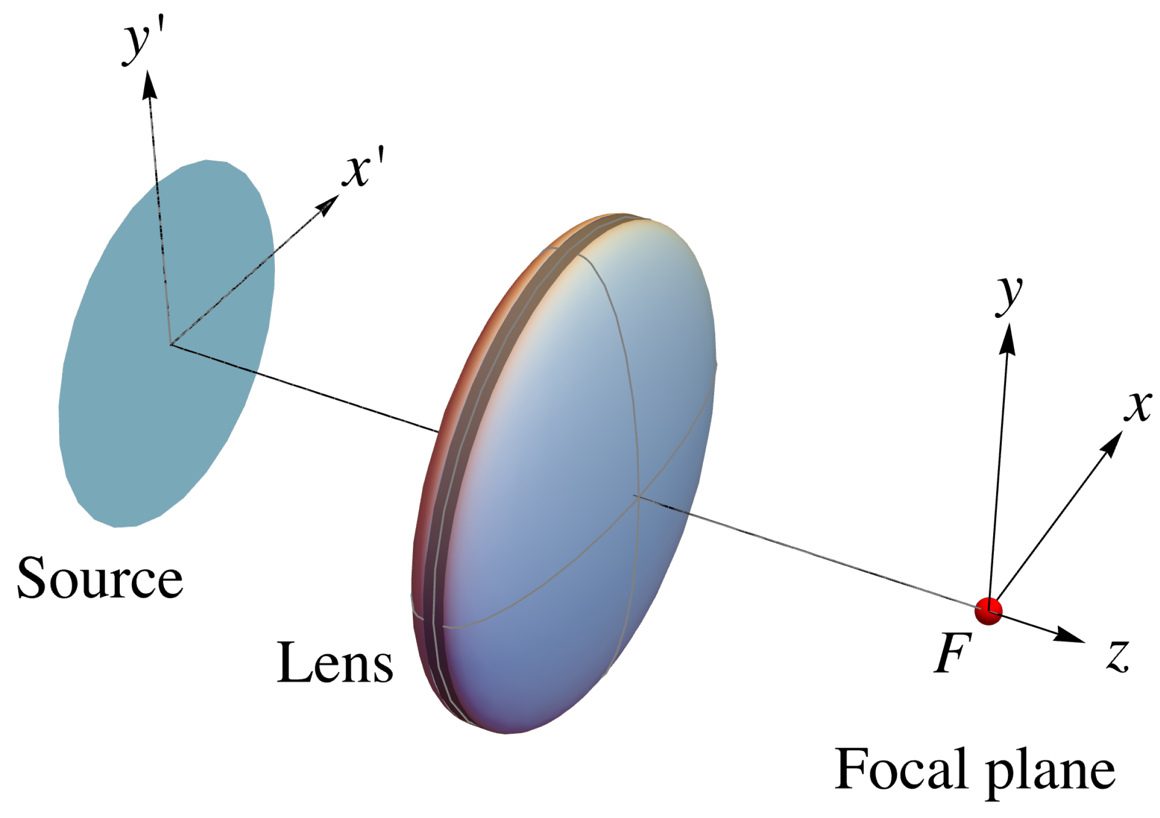
2. Focusing
3. The Scintillation Index
4. Gaussian Schell-Model Sources
- (1).
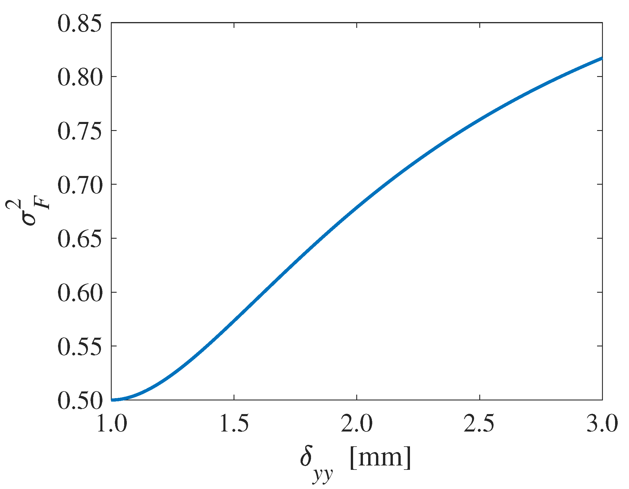
- For an unpolarized source, and . The index of the source then attains its minimum value , and, according to Equation (18), the scintillation index at focus equalsThe dependence of on the coherence radius is illustrated in Figure 2. It is seen that if is equal to , then . In all other cases the lens significantly increases the scintillation.
- (2).
- For a fully polarized source , and the scintillation index across the source takes on its maximum value . The constraint given by expression (12) implies that now . On using this in (13) it follows that , meaning that all coherence radii, and hence also all factors , are equal. In this case, the scintillation index at the geometrical focus also takes on its maximum value, i.e.,It is worth noting that any partially coherent, linearly polarized beam always produces a maximum scintillation index at focus , even when its spatial coherence is not Gaussian as is assumed in Equation (11). This can be seen as follows. Without loss of generality, we can take the direction of linear polarization to be along the x-axis. Then, is the only non-zero CSD matrix element of the field in the front focal plane. Consequently, is the only non-zero element at the geometrical focus. The application of Equation (8) then immediately yields that .
- (3).
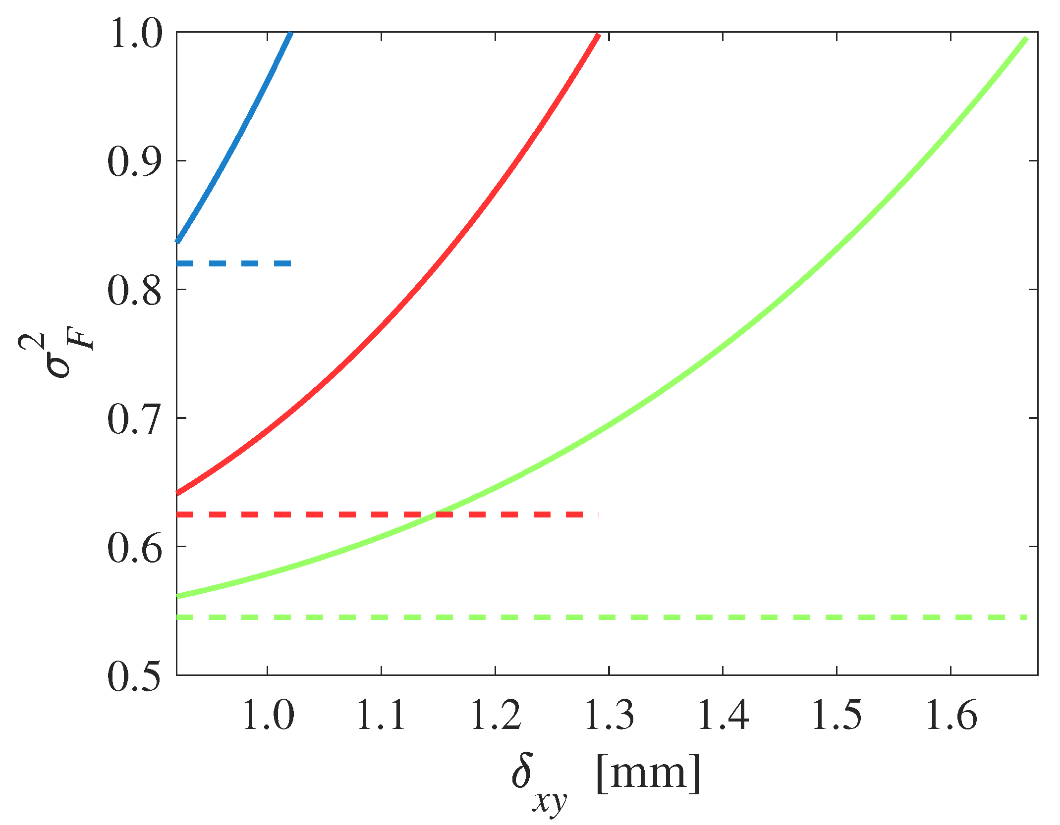
- For a partially polarized source with equal spectral densities of the two Cartesian field components , we find from Equations (17) and (18) thatAs an example, we set and let vary between its bounds given by (12), for three selected values of . The resulting scintillation index at focus is shown in Figure 3. In all three cases the scintillation index at focus is significantly larger than its counterpart in the front focal plane (dashed line). Furthermore, in all three cases, the index attains its maximum value of unity when reaches its upper bound.
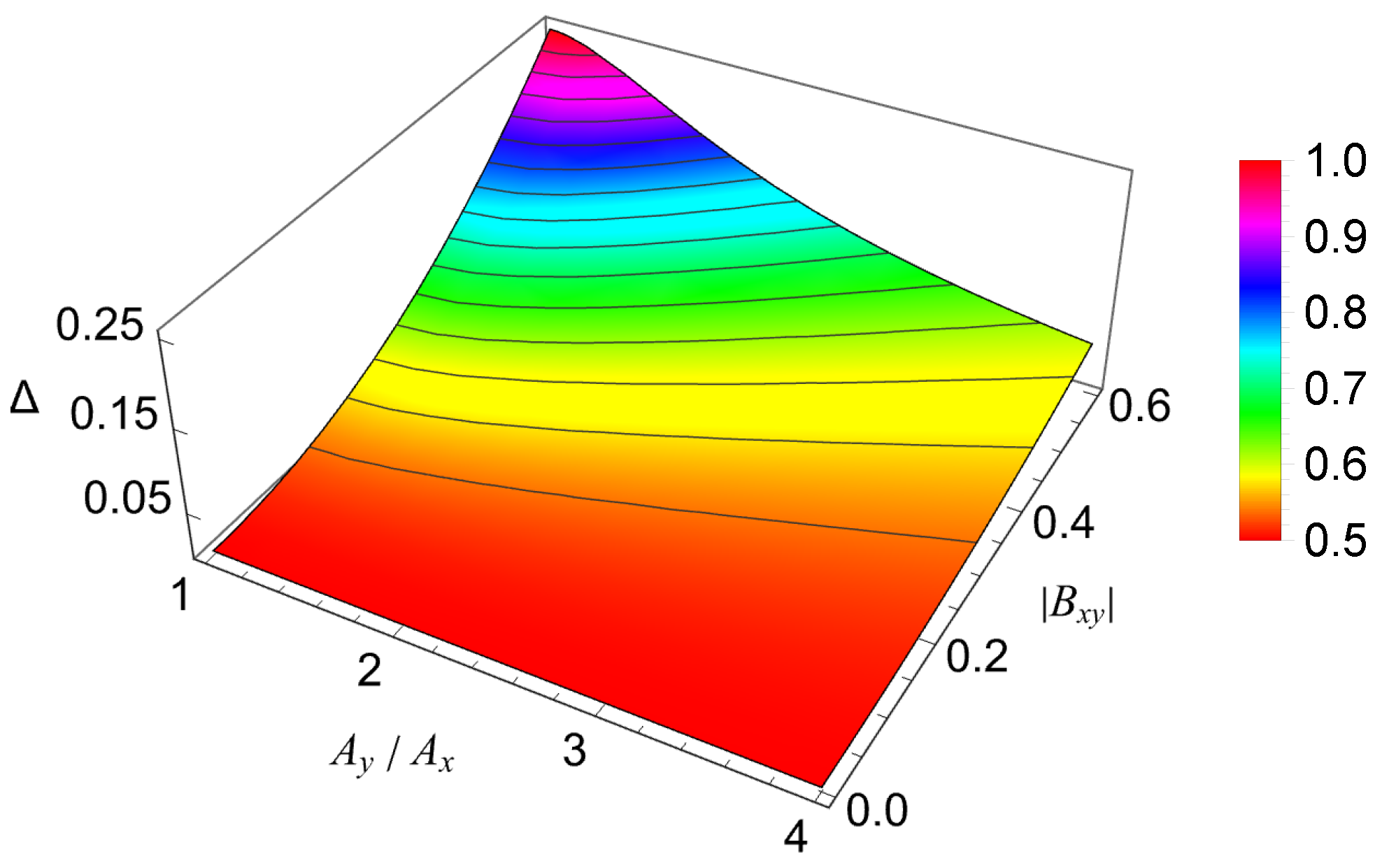
- (4).
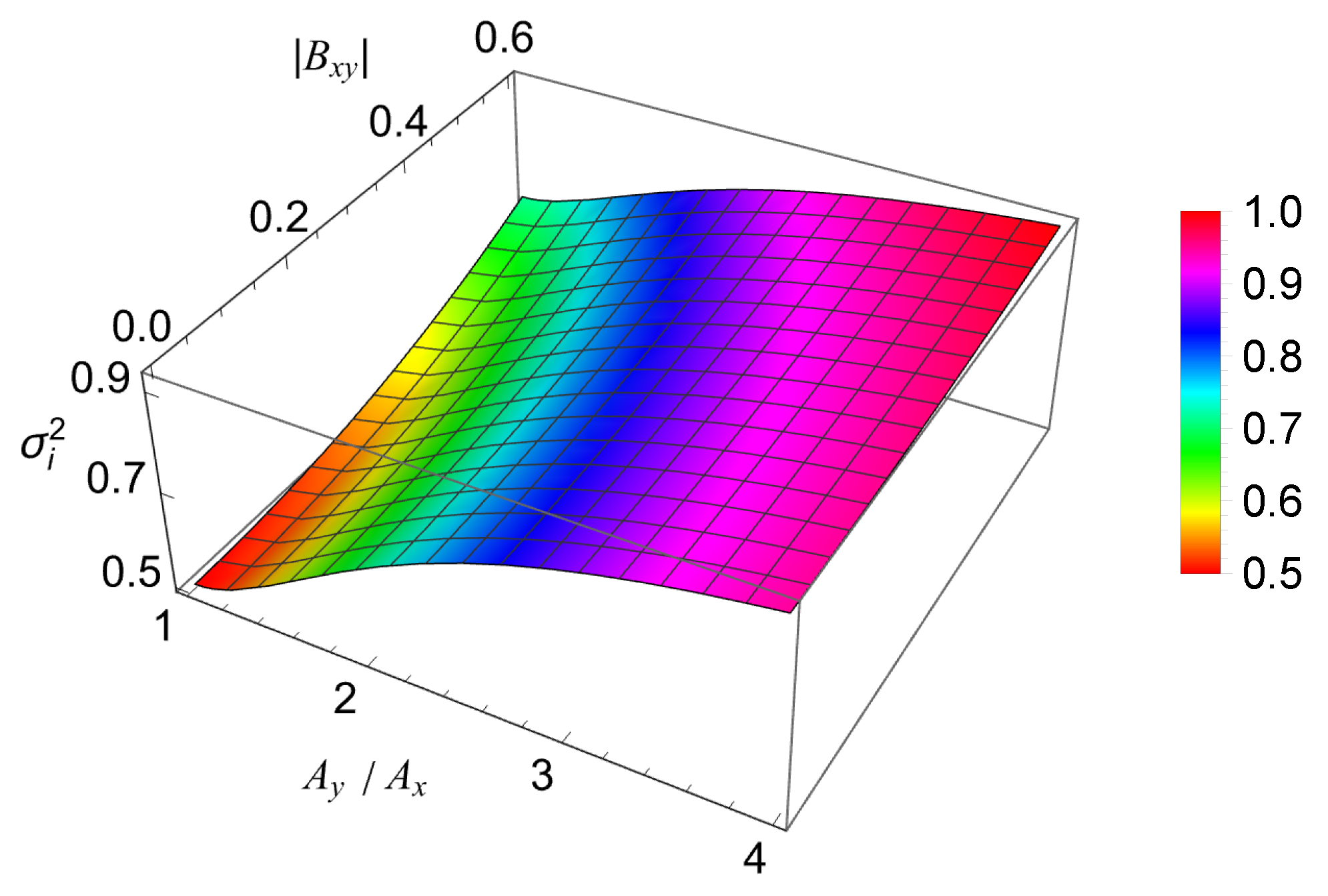
- When the amplitudes of the two field components are not equal , Equations (17) and (18) cannot be further simplified. The behavior of the uniform scintillation index in the front focal plane is illustrated in Figure 4. The three independent coherence radii are fixed, and is varied over its range given by the realizability conditions. It is seen that the index in the front focal plane grows with increasing ratio as well as with increasing . Clearly, the scintillation at focus also depends on these quantities. The difference between the two indices, , is plotted in Figure 5, and reaches its maximum when . In all cases, the scintillation at focus is larger than the scintillation in the front focal plane. The increase due to focusing can be as high as 0.25, which in that case is an increase of .
5. Conclusions
Author Contributions
Funding
Institutional Review Board Statement
Informed Consent Statement
Data Availability Statement
Conflicts of Interest
References
- Mandel, L.; Wolf, E. Optical Coherence and Quantum Optics; Cambridge University Press: Cambridge, UK, 1995. [Google Scholar]
- Wolf, E. Introduction to the Theory of Coherence and Polarization of Light; Cambridge University Press: Cambridge, UK, 2007. [Google Scholar]
- Yiqun, Z.; Mingfeng, X.; Mingbo, P.; Qiang, C.; Mengjie, Z.; Shuangcheng, C.; Kun, Q.; Ning, J.; Xiangang, L. Experimental demonstration of an 8-Gbit/s free-space secure optical communication link using all-optical chaos modulation. Opt. Lett. 2023, 48, 1470–1473. [Google Scholar]
- Andrews, L.C.; Phillips, R.L. Laser Beam Propagation through Random Media, 2nd ed.; SPIE: Bellingham, WA, USA, 2005. [Google Scholar]
- Kuebel, D.; Visser, T.D. Generalized Hanbury Brown-Twiss effect for Stokes parameters. JOSA A 2019, 36, 362–367. [Google Scholar] [CrossRef] [PubMed]
- Wu, G.; Kuebel, D.; Visser, T.D. Generalized Hanbury Brown-Twiss effect in partially coherent electromagnetic beams. Phys. Rev. A 2019, 99, 033846. [Google Scholar] [CrossRef]
- Goodman, J.W. Introduction to Fourier Optics, 2nd ed.; McGraw Hill: New York, NY, USA, 1996. [Google Scholar]
- Visser, T.D.; Agrawal, G.P.; Milonni, P.W. Fourier processing with partially coherent fields. Opt. Lett. 2017, 42, 4600–4602. [Google Scholar] [CrossRef] [PubMed]
- Wadood, S.A.; Nussbaum, B.E.; Visser, T.D.; Brown, T.G.; Agrawal, G.P.; Vamivakas, A.N. A Fourier processor for partially coherent fields. OSA Continuum. 2020, 3, 2843–2850. [Google Scholar] [CrossRef]
- Wang, Y.; Yan, S.; Kuebel, D.; Visser, T.D. Generalized Hanbury Brown–Twiss effect and Stokes scintillations in the focal plane of a lens. Phys. Rev. A 2019, 100, 023821. [Google Scholar] [CrossRef]
- Yonglei, L.; Zhen, D.; Yahong, C.; Yangjian, C. Research advances of partially coherent beams with novel coherence structures: Engineering and applications. Opto-Electron. Eng. 2022, 49, 220178. [Google Scholar]
- Xin, L.; Qian, C.; Jun, Z.; Yangjian, C.; Chuanhao, L. Measurement of optical coherence structures of random optical fields using generalized Arago spot experiment. Opto-Electron. Sci. 2023, 2, 220024. [Google Scholar]
- Wolf, E. Correlation between photons in partially polarized light beams. Proc. Phys. Soc. 1960, 76, 424–426. [Google Scholar] [CrossRef]
- Setälä, T.; Lindfors, K.; Kaivola, M.; Tervo, J.; Friberg, A.T. Intensity fluctuations and degree of polarization in three-dimensional thermal light fields. Opt. Lett. 2004, 29, 2587–2589. [Google Scholar] [CrossRef] [PubMed]
- Gori, F.; Santarsiero, M.; Borghi, R.; Ramírez-Sánchez, V. Realizability condition for electromagnetic Schell-model sources. JOSA A 2008, 25, 1016. [Google Scholar] [CrossRef] [PubMed]


Disclaimer/Publisher’s Note: The statements, opinions and data contained in all publications are solely those of the individual author(s) and contributor(s) and not of MDPI and/or the editor(s). MDPI and/or the editor(s) disclaim responsibility for any injury to people or property resulting from any ideas, methods, instructions or products referred to in the content. |
© 2023 by the authors. Licensee MDPI, Basel, Switzerland. This article is an open access article distributed under the terms and conditions of the Creative Commons Attribution (CC BY) license (https://creativecommons.org/licenses/by/4.0/).
Share and Cite
Xu, J.; Gao, Y.; Cai, Y.; Visser, T.D. Scintillation Increase Induced by Focusing (Invited). Photonics 2023, 10, 604. https://doi.org/10.3390/photonics10050604
Xu J, Gao Y, Cai Y, Visser TD. Scintillation Increase Induced by Focusing (Invited). Photonics. 2023; 10(5):604. https://doi.org/10.3390/photonics10050604
Chicago/Turabian StyleXu, Jia, Yaru Gao, Yangjian Cai, and Taco D. Visser. 2023. "Scintillation Increase Induced by Focusing (Invited)" Photonics 10, no. 5: 604. https://doi.org/10.3390/photonics10050604