1. Introduction
The Metaverse is one of the most popular concepts in the global technology scene nowadays, with virtual reality technology being at the core of the whole metaverse concept. Currently, major technology companies around the world are devoting a lot of resources to virtual reality technology in order to be able to integrate their products into the Metaverse. Virtual reality is the use of computers to generate a virtual three-dimensional world so that the user’s senses of touch, sight, and hearing can be experienced as if they were in the virtual world.
Virtual reality first emerged in 1956 when filmmaker Morton Heilig invented a movie-viewing device called Sensorama, equipped with a 3D display, an odor generator, a stereo sound box, a vibrating seat, and a head hair drier. This allowed the experience of using the equipment to watch a movie to be immersive, and the device was the world’s first virtual reality device [
1]. In 1968, MIT developed the Sword of Damocles head-mounted display, a complex device that required a robotic arm (manipulator) to suspend the device and the user to wear it on their head for operation. In 1985, NASA developed a virtual reality head-mounted display with an LCD display virtual reality headset. In recent years, international technology companies have also made significant investments in virtual reality technology and scientific development [
2,
3,
4,
5]. In 2014, Facebook’s entrepreneur Mark Zuckerberg purchased Oculus for USD 2 billion, a significant step that attracted the attention of the market. At present, Apple, Samsung, Sony, Microsoft, Google, and other international technology companies have their own virtual reality headset products [
6,
7].
The development of virtual reality technology in China has been relatively slow compared to international levels. In 2005, Zhao Qiuling et al., at Tianjin University, designed a virtual reality optical system with a field of view of 32 degrees and a distortion of less than 5% [
8]. In 2007, Dewen Cheng et al. of the Beijing Institute of Technology designed a virtual reality optical system with a large field of view using a free surface prism, which enabled the miniaturization and lightening of the device. In 2015, Rui-Wen Pan et al. of National Taiwan University employed a 7.8 mm OLED microdisplay as the image source to design a virtual reality optical system [
9,
10,
11]. In the same year, Xiangbo Lu et al., at the Shanghai Institute of Optical Precision Machinery, Chinese Academy of Sciences, used two optical plastics, PMMA and pc, to design a lightweight virtual reality optical system [
12]. Many technology companies in China are also currently developing virtual reality head-mounted displays, such as Tech Data (iflytek), Pico, HTC, and Xiaopai (pimax), all of which have released their own virtual reality head-mounted display products. Virtual reality technology has also evolved from its initial use in research to its existing use in the military, technology, medical, and educational fields.
There are several virtual reality products on the market at present, of which virtual reality head-mounted displays are the most representative. However, since virtual reality head-mounted displays require a series of components, such as monitors, optics, and headphones, in order for users to view the images and have a sense of immersion, the overall size and weight of the head-mounted display is large, and users may feel uncomfortable after wearing it for a long time [
13,
14]. To make virtual reality head-mounted displays small and lightweight, it is first necessary to optimize the structure of the optical system of the virtual reality head-mounted display. When optimising the optical system structure, it is important to understand the imaging principles of the human visual system. This study analyzes the human visual system and investigates the design of virtual reality headset displays based on the principles of the human visual system. It also summarizes the existing research on the optical system of virtual reality head-mounted displays, examines the basic principles of each design, compares and analyzes the performance parameters of each display, and provides some insight into the future development of virtual reality head-mounted displays.
2. Human Visual System
The biology eyeball system is a naturally evolved and highly perfect optical imaging system, and many optical systems are currently designed based on the principles of bionics, which imitate the biological eye system [
15,
16]. As human eyes are the most direct receiving system for information from the external environment, researchers refer to the principles of human eye vision and various parameters of the human eyes before designing optical systems for use with human eyes. Therefore, before studying virtual reality headset displays, it is necessary to first examine the imaging principle of human eye vision and evaluate the advantages and disadvantages of various virtual reality headset display design solutions by interpreting the principle of human eye stereo imaging.
The distribution of the field of view of the human eye is shown in
Figure 1. The field of ocellus-level view can reach a maximum of 156 degrees, the binocular-level view can reach a maximum of 188 degrees, and the binocular coincidence view is approximately 120 degrees. The vertical view of human eyes can be up to 140 degrees, with a maximum of 65 degrees upwards and 75 degrees downwards. The normal viewing angle of human eyes is approximately 60 degrees, and human eyes will only focus on things within the 60 degree range [
17,
18,
19]. As human eyes recognize and acquire external information through the binocular overlap area, the binocular overlap area is essential for stereo vision. In addition, the peripheral non-overlap area is for tasks such as viewing and balancing the overlap area. The distance between human binoculars is commonly 65 mm, and the minimum view angle that can be observed is approximately 0.5′, which corresponds to a visual acuity (Visual acuity) of 20/10 [
20]. Therefore, when developing a virtual reality headset display, the size of the headset display needs to satisfy the range of viewing angles of human eyes. Only by increasing the field of view and referring to the field of view of human eyes will the user be able to view a larger range of images and view the image material within the full range of the field of view of human eyes.
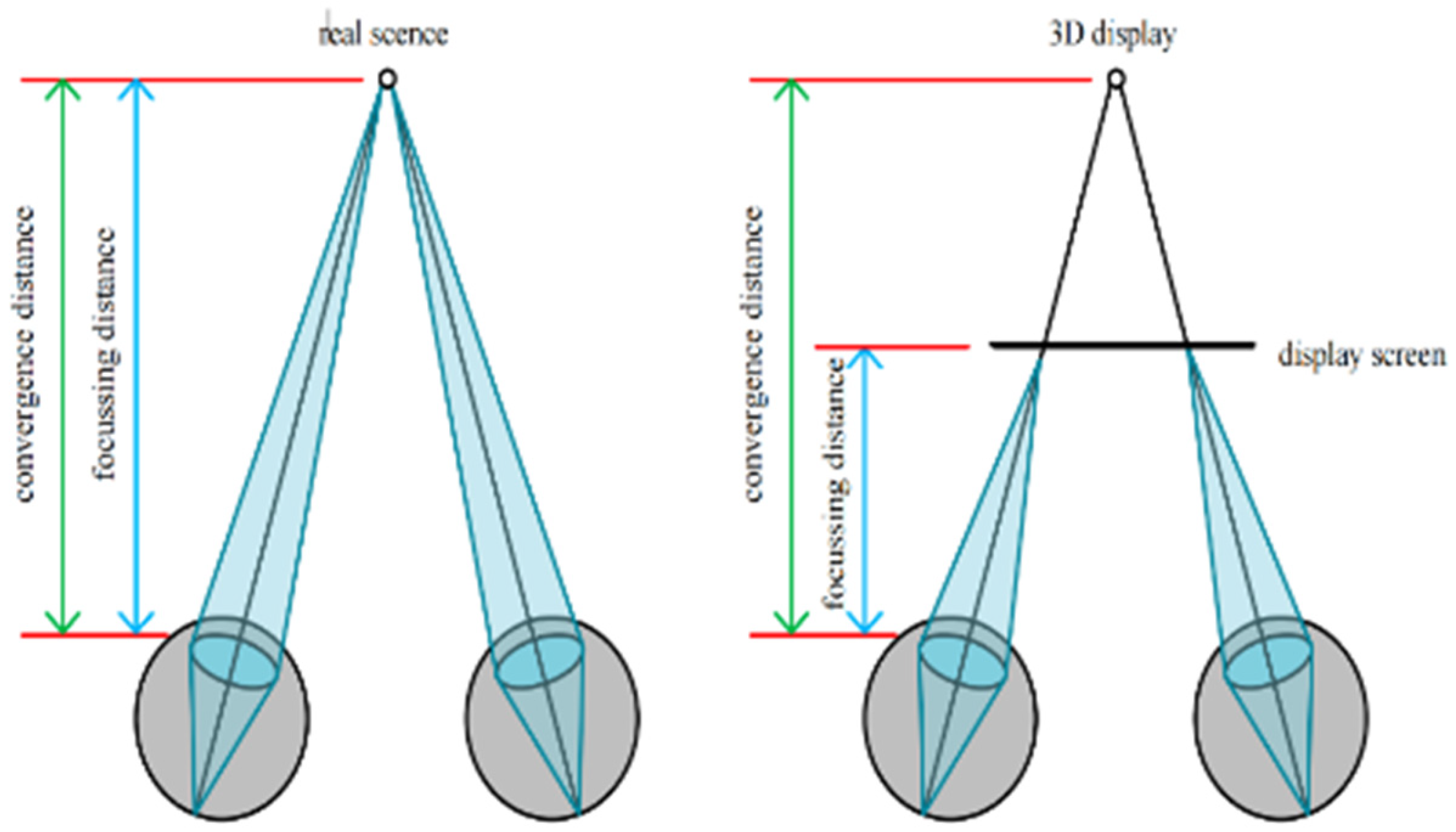
The virtual reality headset display provides the impression of immersion to the user because the image presented in the virtual reality headset display offers the users a stereoscopic impression. When using a virtual reality headset display, the focusing distance is the range between the human eyes and the monitor, and the convergence distance is the distance between the human eyes and the observed objects in the image [
21,
22,
23,
24], as shown in
Figure 1.
With the difference between 3D imaging and the conventional way of viewing the human eyes, visual fatigue and discomfort may occur when wearing a virtual reality headset display for long times. Therefore, reducing visual fatigue and vertigo is the primary issue that needs to be addressed in the optical design of virtual reality headset displays.
3. The Development of Research into Helmet-Based Virtual Reality Display Systems
A helmet display system (HMD) is a device that provides the users with visual information to create an immersive experience. It is worn on the user’s head and follows the movement and rotation of the user’s head. The software is specifically designed to allow the image to change as the user turns his or her head [
25]. A helmet display system (HMD) is a device that provides the users with visual information to create an immersive experience. It is worn on the user’s head and follows the movement and rotation of the user’s head. The software is specifically designed to allow the image to change as the user turns his or her head [
26]. The helmet display system can be divided into an eyepiece helmet display system and a non-imaging helmet display system based on the object–image relationship. The principle of the eyepiece helmet display system is that the image information produced by a low-profile display is passed through an optical system that distances the image from the human eyes and magnifies the size of the image. The image is usually stretched to a distance of 3–5 m in front of the human eyes. In addition, because there is a certain parallax between the image of the left and right eyes, the users will have a sense of depth [
27,
28,
29]. This paper focuses on the construction of the optical system in several eyepiece helmet display systems, namely, the construction of traditional sphere aspheric, the construction of freeform Fresnel lens, the construction of freeform prism, the construction of the lens array, and the construction of the Pancake lens. This section will introduce the working principles, main functions, and key performance indicators of several optical structures and compare the advantages and disadvantages of the designs.
3.1. Helmet Display with Conventional Lens Set
Virtual reality headset displays require optical structures to magnify and distort the images produced by the microdisplay. The initial optical system in virtual reality headset displays used multiple spherical or aspherical optical lens sets to magnify and distort the image while correcting for optical aberration [
30]. In 1971, Canon undertook the first mass production use of aspherical lenses in their lens products and since then, aspherical lenses have been used in various optical systems.
Virtual reality headset displays are large-field visual optical systems, and the initial virtual reality headset displays were transmittance coaxial visual optical systems [
31]. The main types of these optical systems are Huygens eyepiece, Ramsden eyepiece, RKE eyepiece, Kellner eyepiece, Erfle eyepiece, Symmetrical eyepiece, Fleur eyepiece, and Scidmore eyepiece. The structure and parameters of each eyepiece are shown in
Table 1 below.
The table shows that the larger number of lenses in the lens set, the larger the field of view of the eyepiece and the higher the imaging quality. The field of view of the eyepiece is enhanced when a glued lens is applied to the lens set and the initial aberration of the system is corrected with the addition of the glued lens.
However, when selecting the initial structure of a helmet display, not all of the above lenses fulfil the initial structure requirements. The Huygens eyepiece is not applicable to the initial structure of the helmet display optical system because the image surface of the eyepiece is located between the two lenses and the pupil distance is too short and the field of view is smaller. Kellner eyepieces are not compact since the distance between the glued mirror and the positive lens is larger and the exit pupil distance is smaller, requiring excessive parameters to be optimized when used as the initial structure of a helmet display, making them unsuitable as an initial structure. Symmetrical eyepieces, Erfle eyepieces, Fowler eyepieces, and Scidmore eyepieces are not quite well suited as initial structures for portable helmet displays due to their relatively greater number of lenses, the complexity of their optical structures, and their larger size and weight. Symmetrical eyepieces, Erfle eyepieces, Fowler eyepieces, and Scidmore eyepieces are not quite well-suited as initial structures for portable helmet displays due to their relatively greater number of lenses, the complexity of their optical structures, and their larger size and weight. The Ramsden and RKE eyepieces have a smaller number of lenses and a more compact optical structure, making them particularly well-suited as initial structures for portable helmet displays. The RKE eyepiece uses a double-glued lens set structure, which is able to rectify chromatic aberration and axial aberration, and the separation of the double-glued lens set increases the freedom of optimization, thus making it the preferred optical structure for portable helmet displays [
32,
33]. However, due to the large number and size of optical lenses employed in conventional lens-set helmet displays, which may cause discomfort to users after prolonged wear, mainstream virtual reality helmet displays are currently forgoing the use of conventional lens-set structures in favor of compact and lightweight optical systems.
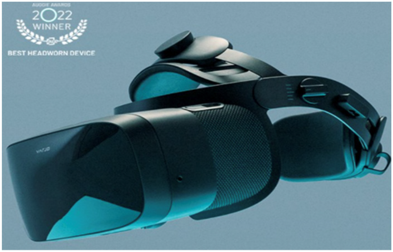
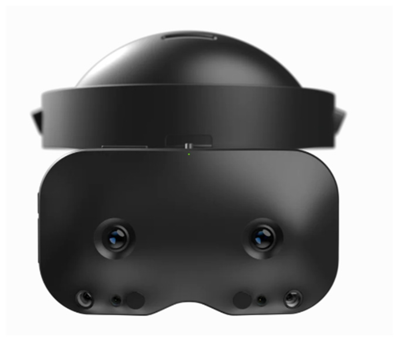
While most virtual reality headset display companies are now avoiding the use of traditional aspheric lenses for their products in order to be lightweight and compact, Varjo is still using aspheric lenses in its optical imaging system in order to achieve high definition and visual reality. In October 2021, Varjo will launch its virtual reality product, the Varjo Aero, which is shown in
Figure 2.
3.2. Free-Form Fresnel-Lens Helmet Displays
With the improvement of free-form design and manufacturing in recent years, the optical lenses available on the market have evolved from spherical lenses and aspheric lenses to the more frequent use of free-form lenses at present. However, a single free-form lens is unable to meet the requirements of different optical products for various performance indicators of optical lenses. Nowadays, researchers are working on the basis of the original free-form optical lens combined with the Fresnel lens to process a new type of combined optical lens.
Fresnel lenses were first introduced and used by Augustin Fresnel in 1822 in a lighthouse lens system. For virtual reality headset displays, researchers have designed and developed virtual reality headset displays based on free-form Fresnel lenses.
Free-form lenses are in fact aspherical lenses that are non-rotationally symmetric. In the process of designing aspheric lenses, the aspheric equation is generally used to describe the surface shape of the aspheric lens, and in the manufacture of aspheric lenses, the mirror surface is machined based on the aspheric equation. For the purpose of design and fabrication of free-form surfaces, the free-form surface shape is usually characterized by mathematical expressions. The following are several functions commonly used to characterize free-form surfaces [
34,
35,
36].
The equation of a double quadratic surface is
in the formula,
,
.
- 2.
(Secondary Zernike surface)
in the formula,
,
.
Compared to conventional spherical lenses and conventional aspheric lenses, free-form lenses can significantly improve image quality, reduce the thickness of the lens, and reduce the number of lenses used in the system. Furthermore, because the free-form surface is designed independently of the point of incidence of each beam, the free-form lens can be corrected for spherical aberration close to the diaphragm and for off-axis aberrations such as meridional coma, astigmatism, and aberration away from the diaphragm. Off-axis aberrations are corrected for. Therefore, free-form surfaces are now the mainstay of optical components in optical systems. However, researchers are not satisfied with the existing advantages offered by free-form surfaces, and with the advent of the Fresnel lens, the advantages of free-form surfaces have been further enhanced. Due to the thinner and lighter mass and thickness of the Fresnel lens, the overall mass can be reduced.
The Fresnel lens is based on the imaging principle of convex lenses and combines different effective refractive areas of different convex lenses to produce a Fresnel lens. A Fresnel lens consists of an infinite number of concentric rings with a spherical surface, with a spherical crown in the center and several rings with various inclination angles on the outside. Each ring band corresponds to a lens, and numerous lenses work together to produce the image. The diagram below shows how a Fresnel lens is formed.
According to the design requirements of the virtual reality headset display, the free-form Fresnel lens was designed using the optical design software, ZEMAX, based on the object–image relationship and aberration theory, and the results are shown in
Figure 3.
Due to the use of free-form Fresnel optics, the degree of freedom for optimization of the optical components is increased, and the free-form Fresnel lens surface shape can be designed according to any indicator requirements of the virtual reality headset display, allowing the virtual reality headset display to achieve effects that cannot be achieved with conventional headset displays; for example, by creating a headset display with a large field of view. The size and mass of the optical system of this solution is much smaller than that of a traditional helmet display. Moreover, virtual reality helmet displays have better imaging quality and reduce the feeling of vertigo due to the optical lens itself, which is more conducive to enhancing the user experience [
37]. Therefore, this design solution is currently used by mainstream virtual reality headset displays in China and other countries.
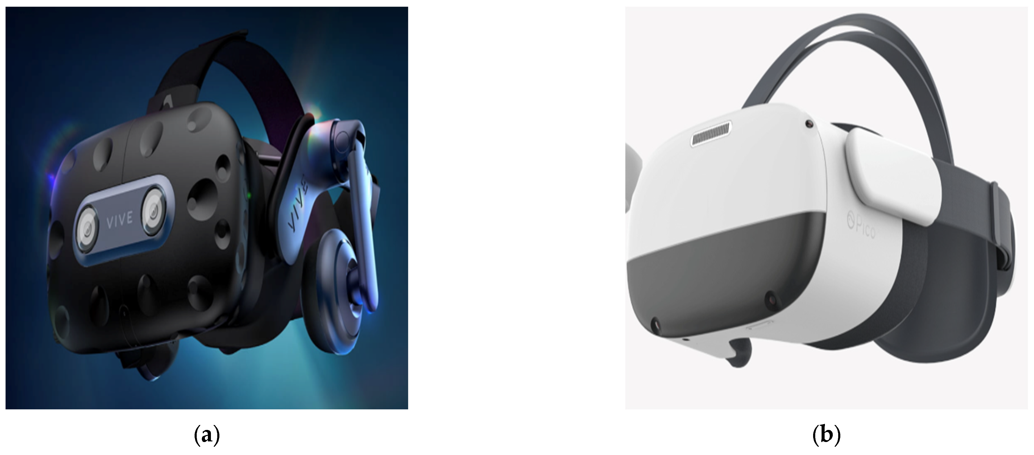
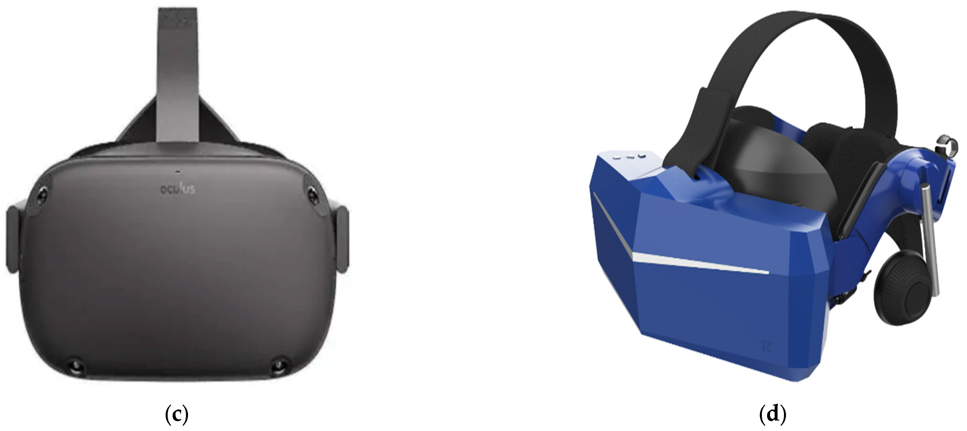
In 2015, HTC Corporation and Valve Corporation jointly developed and released the virtual reality head-mounted display, HTC Vive. In 2017, Pico delivered a new all-in-one Pico Neo series of virtual reality helmet displays. In 2019, Oculus released the flagship virtual reality helmet display, Oculus Quest1. In 2020, XiaoPai Technology released its flagship product, Pimax 8 kx. The optical lenses of the virtual reality head-mounted displays of the major companies above all use Fresnel lenses. The prototype diagram of the above-mentioned four kinds of virtual reality helmet is shown in
Figure 4.
3.3. Free-Form Prismatic Helmet-Mounted Display
In order to minimize the number of virtual reality helmet display lenses, the researchers optimized the design of the prism with the free-form surface lens as the design idea, made the original horizontal prism surface into a free-form surface, and developed a single free-form surface. The reduction of the number of lenses not only solves the problems pertaining to the large volume and high quality of virtual reality head-mounted displays, but also reduces the production cost [
38,
39].
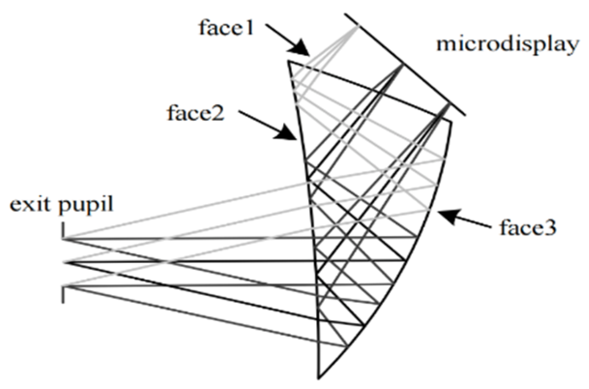
The optical part of the free-form prism HMD generally includes two parts: a free-form prism and a microdisplay. When the light reaches face 2 for the first time, the incident light reaches face 3 after total reflection, and the light reflected on face 3 strikes face 2 again. The incident light does not undergo total reflection this time and enters the human eye through face 2. The schematic diagram of an HMD optical system is shown in
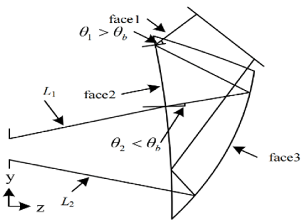
Figure 5, and
Figure 6 presents the schematic diagram of a free-form surface prism that satisfies the condition of total reflection.
To correct the aberrations in two different planes relatively and independently, non-rotationally symmetrical free-form surfaces are used for faces 2 and 3. Face 2 is a deformed aspheric surface with two different curvatures and conic section constants along the orthogonal direction, and the descriptive equation is Formula (2).
Face 3 is the polynomial surface, and the descriptive equation is as follows:
- 3.
(Extended polynomial coefficients)
In the equation,
C is the radius of curvature of the surface and is the
i-th term extended polynomial coefficients. Face 1 is a rotationally symmetric metasurface and the descriptive equation is as follows:
where
C is the radius of curvature,
k is the quadratic surface coefficient, and
ABC is the 468th order aspheric coefficient, respectively.
It can be seen from
Figure 5 that the number of optical lenses of the free-form optical element is smaller than that of the rotationally symmetric optical element, and the overall length of the optical system is greatly shortened. The mass and volume of the optical system has been drastically reduced.
In 1998, Okuyama and Yamazaki first proposed the use of free-form prisms in virtual reality HMDs. After years of research and development, the manufacturing technology of free-form prisms HMDs has matured. In 2007, the research group of the Beijing Institute of Technology designed and developed a free-form surface prism-based helmet-mounted display, which is suitable for scientific research and entertainment. The Lynx Mixed Reality company, led by Stan Larroque and others, has developed the Lynx-R1, a mixed reality (MR) headset display that combines virtual reality (VR) and augmented reality (AR) display capabilities, using a four-piece freeform prism assembly.
Figure 7 shows a prototype of the product.
3.4. Lens Array Helmet Displays
With the development of technology and the improvement of the quality of life, researchers and common users have increasingly high requirements for virtual reality headset displays, which not only need to have sharp imaging quality, but also need to be miniaturized and lightweight and to reduce the occurrence of vertigo after a long period of use. Therefore, the single use of free-form Fresnel lenses and free-form prisms to prepare virtual reality headset displays cannot satisfy the current requirements for virtual reality headset displays in various industries and fields [
40,
41,
42,
43]. In 1908, Lippmann of France proposed the concept of microlens arrays, and in 1978, Anderson of the United States first proposed the use of microlens arrays for optical system imaging. In 2021, Kiseung Bang et al. from Seoul National University designed a virtual reality headset display with a wide field of view of 102° × 102° using a lens array [
44]. The emergence of microlens arrays has led to a completely new design idea for the optical imaging system of virtual reality headset displays. With high diffraction efficiency, high filling factor and a wide working waveband, microlenses can meet the imaging requirements of optical components for virtual reality headset displays.
The use of microlens arrays to create the optical system of a virtual reality headset display is the use of the optical design software ZEMAX to develop microlens arrays. The design principle of microlens arrays is based on the refraction and transmission theory of optics, where each microlens in a planar lens array has exactly the same parameters and requires a single lens to be optimised for the design. Typical structural parameters for a single microlens include the radius of curvature
r1r2 on both surfaces, and thickness
d. The optical parameters are focal distance, entry pupil, field of view, and exit pupil distance. According to the basic theory of optical imaging, the focal distance is as follows:
The field of view of a microlens is related to the objective distance:
where
is the objective distance of the microlens. The back intercept of a microlens is
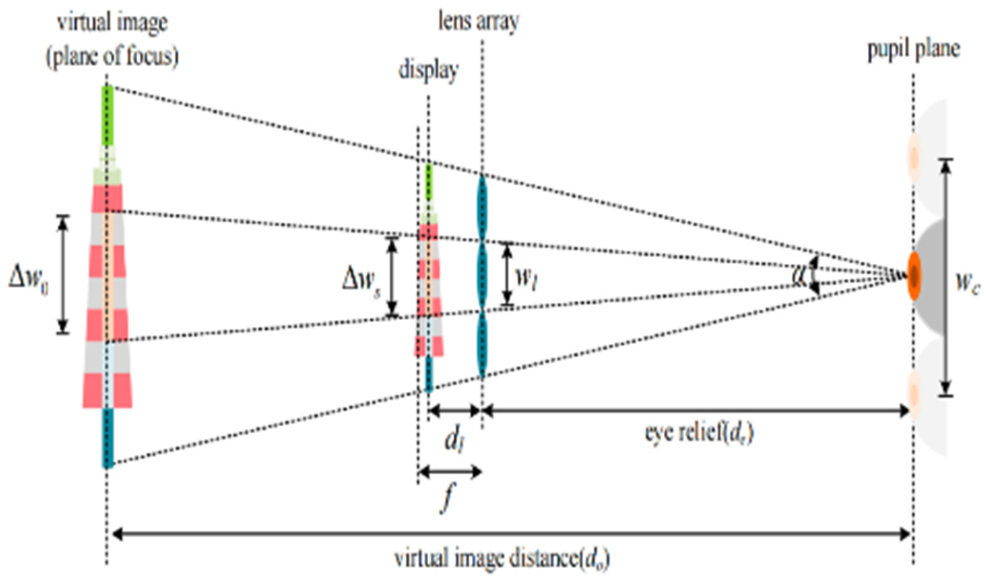
For the design of a microlens array structure applicable to a virtual reality headset display, multiple small magnifying lenses are actually inserted between the pupil of the human eye and the microdisplay to magnify the image of the microdisplay [
45,
46]. The relationship between the microdisplay, the microlens array, and the pupil of the human eye is shown in
Figure 8.
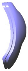
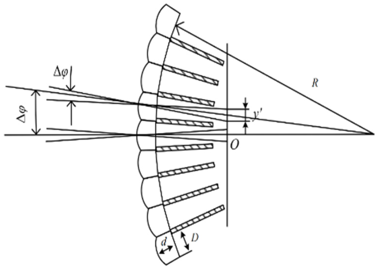
Furthermore, virtual reality headset displays with microlens arrays can adopt not only flat microdisplays, but also curved microlens arrays that can be devised for use with curved displays, allowing the field of view of the virtual reality headset display to be further improved. The structure of the curved microlens array is shown in
Figure 9.
In
Figure 9,
r is the radius of curvature, d is the outer diameter, f is the focal length, and the optical axis divides the object space into a number of fields of view at an angle of
, with each microlens converging the light to the receiver at a small specific angle
, where
However, the processing of microlens arrays for optical systems is complex and demanding on both the equipment and the technicians, and the surface structure of the microlens arrays makes them cumbersome to utilize and preserve, making them currently less suitable for use in virtual reality headset displays available to the average user.
3.5. Pancake Structural Helmet Displays
With the popularity of virtual reality headset displays, the demands of users for virtual reality headset displays are no longer limited to clear image quality and compactness and lightness. For the sake of portability, users are expecting a greater overall size of the virtual reality headset display [
47,
48]. However, the optical system itself has properties that require a long enough optical path distance for the light to travel through the overall optical system if the image of the microdisplay is to be magnified [
49,
50]. On this basis, if one wants to optimize the volume of the virtual reality headset display, one requires an increase in the number of light reflections in the optical system and an enhancement of the effective optical path distance of the light [
51,
52]. Therefore, based on this design concept, researchers have developed an optical folding scheme (Pancake lens) that combines refractive optics or polarization theory with a lens array. The Pancake optical scheme is based on this combination.
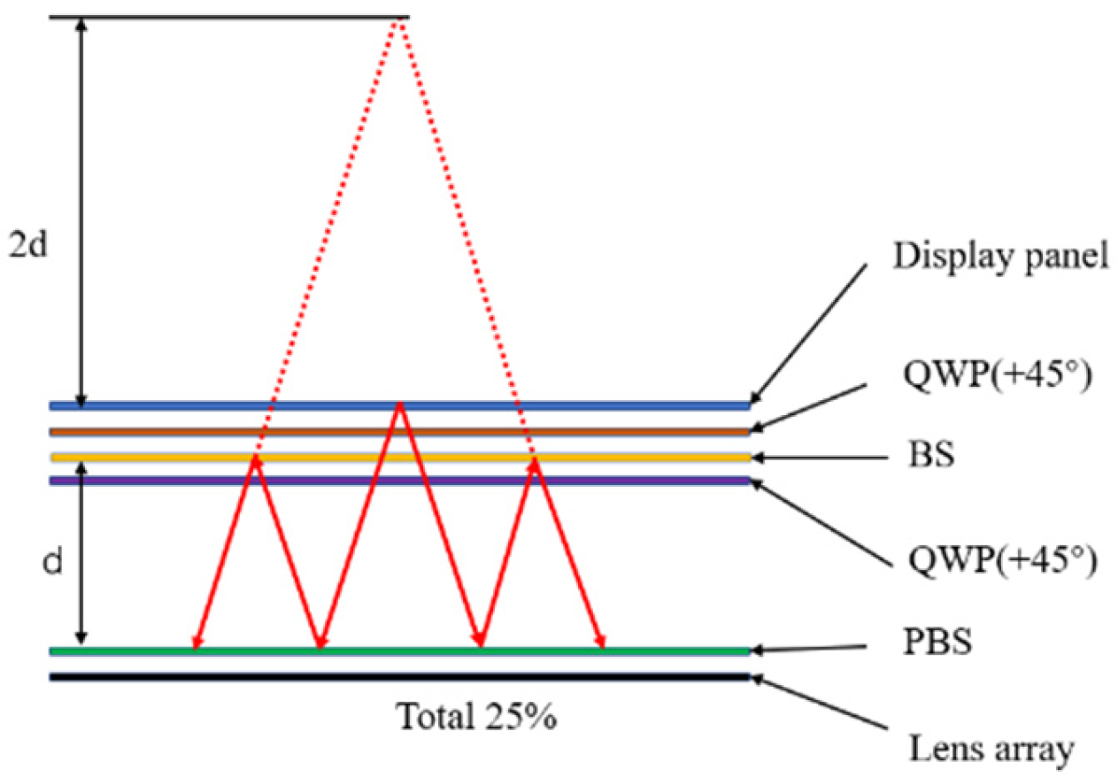
The structure of the Pancake lens system typically consists of four parts: a quarter-wave plate (QWP), a beam splitter (BS), another quarter-wave plate (QWP), and a polarizing beam splitter (PBS), in order of the microdisplay to the lens array. The structure is shown in
Figure 10.
First, the microdisplay emits linearly polarized light, which changes state of polarization to the initial linearly polarized light and is reflected by the PBS as the light passes through the QWP, BS, and another orthogonal polarizer to the QWP. Afterwards, the light is reflected by the BS and the light is incident on the PBS again. At the same time, the light passes through the single QWP twice and becomes orthogonally linearly polarized light. At this point, it passes through the PBS and propagates towards the lens array. Since the light from the panel is repeatedly propagated three times between the BS surface and the PBS surface, the light is optically equivalent to light from a much greater distance, twice the distance between them, and since the QWP is incredibly thin and the PBS and BS are closely connected to the microdisplay and lens array, we can obtain an effective light range three times longer than the physical system distance between the microdisplay and the lens array. As a result, the system distance required for a virtual reality headset display designed by using the Pancake structure can be reduced to 1/3 of the required optical system distance [
53]. However, such a design also has its drawbacks, as the Pancake system suffers from a shortfall in optical efficiency, with 50% of the light lost during both reflection and propagation of the BS, resulting in a theoretical total optical efficiency of only 25% [
54,
55]. Therefore, when a virtual reality headset display uses Pancake, the overall light intensity of the microdisplay must be enhanced so that the user does not have a bad experience with the virtual reality headset display with the Pancake system because of low light efficiency.
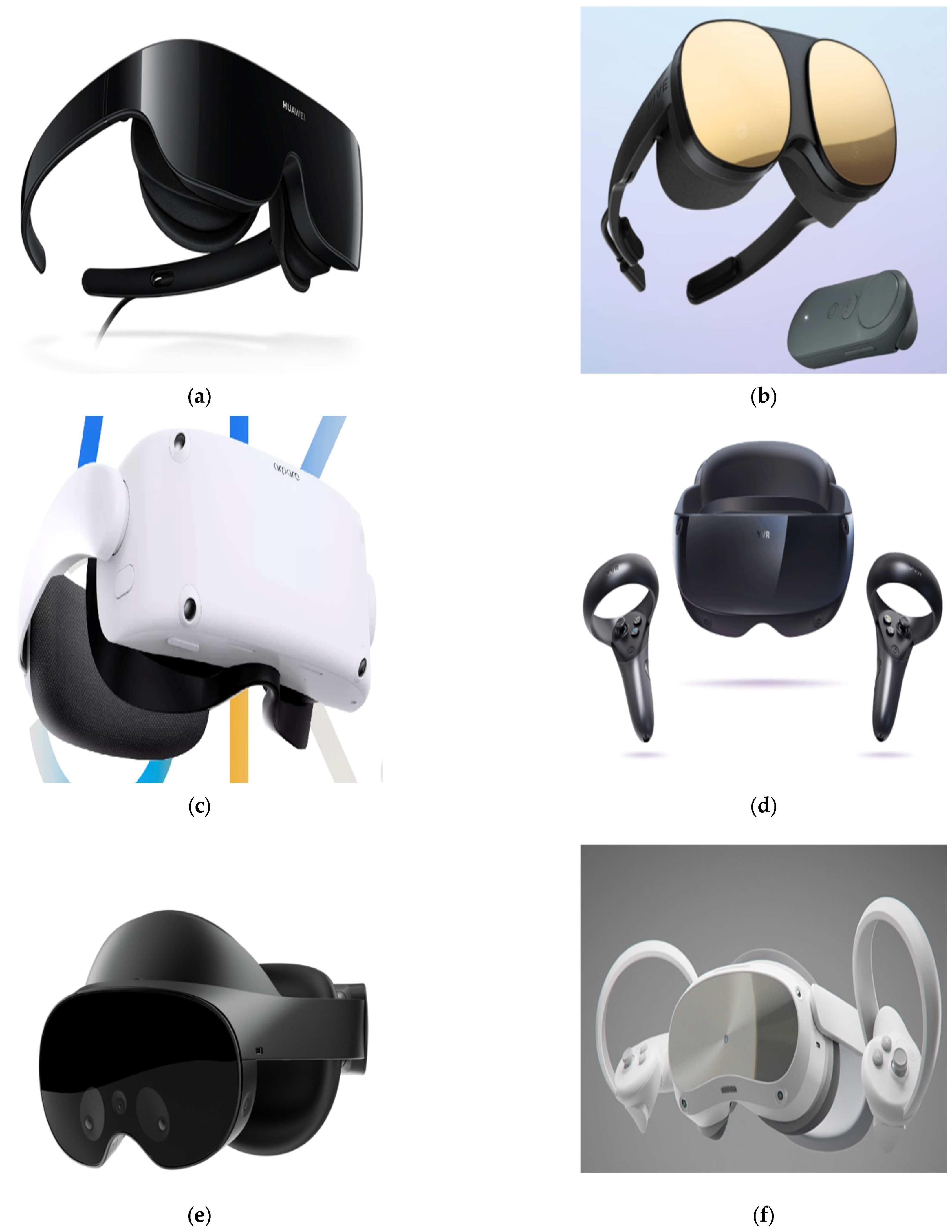
The vast majority of virtual reality headset display companies are now using the Pancake solution as the primary design solution for their successor products. In 2019, Huawei announced the Huawei VR glass with its Pancake solution. In 2021, the HTC Vive series launched the HTC ViveFlow with the Pancake solution. In May 2022, Arpara released the 5k VR all-in-one with Pancake combined with Micro-OLED. In July 2022, YVR releases a new generation of VR all-in-one machines with the Pancake solution. In 2022, Meta released the next generation of virtual reality headset display, Meta Quest Pro, which is equipped with eye-tracking modules. In 2023, ByteDance launched a brand-new headset display product, Pico 4 Pro, which uses the Pancake scheme.
Figure 11 shows a prototype of each product.
4. Conclusions and Discussion
With the rapid change of technology around the world, virtual reality technology has developed at a remarkable pace in recent years. Technology products such as smartphones and computers have grown from being accessible to a relatively small percentage of the population to widespread adoption, bringing technology products closer to the average user. Virtual reality products are trending towards general availability, and virtual reality headset displays are becoming more relevant to the lives of common users. In summary, this paper first provides the design criteria for virtual reality headset displays by introducing the visual system of the human eye, and also points out several issues that need to be addressed in virtual reality headset displays, such as field of view, resolution, display brightness, and volume size. Afterwards, several optical system parts for virtual reality headset displays with various design ideas are presented, which are currently some of the more popular design solutions. Through the analysis of the principles of these design solutions, the advantages and shortcomings of each solution are contrasted, and examples of products from several large international virtual display headset display companies are given.
5. Prospect
Virtual reality headset display technology is currently expanding beyond the visual experience of the user, and through the integration of innovative technologies with virtual reality techniques, a number of new headset displays have been developed that provide a diverse experience for the user. For example, by adding eye tracking technology to virtual reality headset displays, the user’s eye movements are captured, and through blinking and other actions, the virtual reality headset display can give a wide range of commands to the virtual reality headset device without the use of a handle, freeing up the user’s hands and enabling them to have a whole new experience. The combination of the virtual reality headset display with retinal projection technology, for instance, has led to a fundamental change in the imaging principle of the headset display. With the adoption of retinal projection technology, the original display can be completely replaced, and the size and weight of the virtual reality headset display reduced significantly. Furthermore, virtual reality headset displays are now becoming integrated, and by adding several cameras to the outside of the helmet and analyzing the images captured by the cameras, it is possible to remove the constraints of peripheral positioning devices and realize spatial positioning by simply applying displacement calculations to the user with the helmet display.
Currently, there are some shortcomings in virtual reality headset displays. The number of devices that have been added to the helmet is constantly increasing, making the overall number of devices inside the helmet greater, and resulting in increased volume and weight. Moreover, researchers now want to add more and more new technologies to virtual reality headsets. However, the limitations of the size of the virtual reality headset itself make it challenging to implement the new technologies that are currently being added to the virtual reality headset to the level intended. Instead of bringing an enhanced user experience, the immature technology that has been forcibly integrated into the virtual reality headset has greatly diminished the user experience.
Virtual reality headset displays are now seen in a variety of fields and industries, and virtual reality technology has become one of the most popular technologies in the world. Virtual reality headset displays are in their initial stages, and in the future, virtual reality headset displays will grow in the direction of being more lightweight and intelligent. At present, virtual reality technology has been fully merged with augmented reality technology. In the future, these two technologies will be further integrated to create new products with the rapidly developing 5G/6G technology. At this point in time, virtual reality headset displays only deliver a visually immersive experience to the user. In future, virtual reality headset displays will be able to enhance the senses of hearing, smell, and touch, providing the ultimate user experience in all aspects. Virtual reality headset displays will become widely popular, bringing improved convenience and a more comfortable user experience.
Author Contributions
Conceptualization, Z.R. and X.F.; methodology, Z.R.; software, Z.R.; validation, Z.R., Y.L. and J.Z.; formal analysis, X.F.; investigation, K.D.; resources, Z.R., Y.L. and J.Z.; data curation, Y.L. and J.Z.; writing—original draft preparation, Z.R.; writing—review and editing, X.F.; visualization, Z.R.; supervision, K.D.; project administration, Z.R.; funding acquisition, K.D. All authors have read and agreed to the published version of the manuscript.
Funding
This research received no external funding.
Institutional Review Board Statement
Not applicable.
Informed Consent Statement
Not applicable.
Data Availability Statement
The data used in this research are available from the corresponding author upon reasonable request.
Conflicts of Interest
The authors declare no conflict of interest.
References
- Li, L.; Escuti, M.J. Super achromatic wide-angle quarter-wave plates using multi-twist retarders. Opt. Express 2021, 29, 7464–7478. [Google Scholar] [CrossRef] [PubMed]
- Zhang, Z.; Li, Y.; Guo, J.; Weng, D.; Liu, Y.; Wang, Y. Vision-tangible interactive display method for mixed and virtual reality: Toward the human-centered editable reality. J. Soc. Inf. Disp. 2019, 27, 72–84. [Google Scholar] [CrossRef]
- Elliott, E.; Norton, K.; Humlhreys, M. FREEFORM OPTICS DESIGN Optical design challenges in virtual, and augmented reality. Laser Focus World 2018, 54, 45–48. [Google Scholar]
- Lungu, A.J.; Swinkels, W.; Claesen, L.; Tu, P.; Egger, J.; Chen, X. A review of the development of application scenarios based on 5G VR technology. Mech. Res. Appl. 2021, 34, 203–206. [Google Scholar]
- Zhang, H.; Jin, Y.; Liu, Y.X.; Niu, L. A Review of Virtual Reality (VR) Technology and Development Research. Inf. Comput. 2019, 31, 126–128. [Google Scholar]
- Davidson, T.J.; Sanderson, P.M. A review of the effects of head-worn displays on teamwork for emergency response. Ergonomics 2022, 65, 188–218. [Google Scholar] [CrossRef]
- Li, H.; Zhang, X.; Shi, G.; Qu, H.; Wu, Y.; Zhang, J. Review and analysis of avionic helmet-mounted displays. Opt. Eng. 2013, 52, 110901. [Google Scholar] [CrossRef]
- An, Y.F.; Zhu, Y.W.; Zhu, R.; Wang, J.; Luo, H. Design and Research of Portable Air Defense Missile Simulation Training System Based on HTC VIVE. Aeronaut. Missile 2018, 15, 61–65. [Google Scholar] [CrossRef]
- Ma, H.K.; Cao, X.; Chu, D.Z.; Wu, N.; Ma, R.; Zhang, S.W.; Shi, Q. Design of underwater zoom lens for marine monitoring. Adv. Lasers Optoelectron. 2017, 54, 68–73. [Google Scholar]
- Gao, Y.; Liu, Y.; Cheng, D.; Wang, Y. A review of the development of helmet-mounted displays. J. Comput. Aided Des. Graph. 2016, 28, 896–904. [Google Scholar]
- Zhu, Y.; Liu, H.G.; Shang, G.H.; Huang, Q.; Dai, Y.P. Military Application of Virtual Display Helmet. Optoelectron. Technol. 2006, 3, 172–176. [Google Scholar] [CrossRef]
- Li, X.D.; Peng, B. A review of the development of virtual reality technology. Technol. Innov. Manag. 2004, 6, 10–14. [Google Scholar]
- Barreiros, J.; Claure, H.; Peele, B.; Shapira, O.; Spjut, J.; Luebke, D.; Jung, M.; Shepherd, R. Fluidic Elastomer Actuators for Haptic Interactions in Virtual Reality. IEEE Robot. Autom. Lett. 2019, 4, 277–284. [Google Scholar] [CrossRef]
- Choi, S.; Gopakumar, M.; Peng, Y.; Kim, J.; Wtzstein, G. Neural 3D Holography: Learning Accurate Wave Propagation Models for 3D Holographic Virtual and Augmented Reality Displays. ACM Trans. Graph. 2021, 40, 1–12. [Google Scholar] [CrossRef]
- Durgin, F.H.; Li, Z. Controlled interaction: Strategies for using virtual reality to study perception. Behav. Res. Methods 2010, 42, 414–420. [Google Scholar] [CrossRef]
- Engel, D.; Schuetz, A.; Krala, M.; Bremmer, F. Body Sway Induced by Oscillatory Optic Flow in Virtual Reality. Perception 2019, 48, 119. [Google Scholar]
- Meng, X.X. Research on the Optical System of Large Field of View Virtual Reality HMD; Graduate School of Chinese Academy of Sciences, Changchun Institute of Optics, Fine Mechanics and Physics: Changchun, China, 2015. [Google Scholar]
- Xu, Y. Research on the Optical System of Immersive Virtual Reality Helmet Display; Suzhou University of Science and Technology: Suzhou, China, 2019. [Google Scholar]
- Cao, F. Overview of VR technology research and development at home and abroad. China Sci. Technol. Inf. 2019, 5, 36–37. [Google Scholar]
- Wu, J.L. Analysis of virtual reality technology and its application. Commun. World 2019, 26, 103–104. [Google Scholar]
- Li, Y.; Yang, Q.; Xiong, J.; Yin, K.; Wu, S.T. 3D displays in augmented and virtual realities with holographic optical elements Invited. Opt. Express 2021, 29, 42696–42712. [Google Scholar] [CrossRef]
- Choi, S.; Jung, K.; Noh, S.D. Virtual reality applications in manufacturing industries: Past research, present findings, and future directions. Concurr. Eng. Res. Appl. 2015, 23, 40–63. [Google Scholar] [CrossRef]
- Danyluk, K.; Ulusoy, T.; Wei, W.; Willett, W. Touch and Beyond: Comparing Physical and Virtual Reality Visualizations. IEEE Trans. Vis. Comput. Graph. 2022, 28, 1930–1940. [Google Scholar] [CrossRef] [PubMed]
- Putze, F.; Vourvopoulos, A.; Lécuyer, A.; Krusienski, D.; Bermúdez Badia, S.I.; Mullen, T.; Herff, C. Editorial: Brain-Computer Interfaces and Augmented/Virtual Reality. Front. Hum. Neurosci. 2020, 14, 144. [Google Scholar] [CrossRef] [PubMed]
- Yao, Y.; Du, Z.; Huang, X.; Li, R. Derivation and simulation verification of the relationship between world coordinates and local coordinates under virtual reality engine. Virtual Real. 2020, 24, 263–269. [Google Scholar] [CrossRef]
- Cheng, D.; Duan, J.; Chen, H.; Wang, H.; Li, D.; Wang, Q.; Hou, Q.; Yang, T.; Hou, W.; Wang, D.; et al. Freeform OST-HMD system with large exit pupil diameter and vision correction capability. Photonics Res. 2022, 10, 21–32. [Google Scholar] [CrossRef]
- Arthur, J.T.J., III; Bailey, R.E.; Williams, S.P.; Prinzel, L.J., III; Shelton, K.J.; Jones, D.R.; Houston, V.E. Review of head-worn displays for the Next Generation Air Transportation System. Opt. Eng. 2017, 56, 051405. [Google Scholar] [CrossRef]
- Bal, M.; Benders, J.; Dhondt, S.; Vermeerbergen, L. Head-worn displays and job content: A systematic literature review. Appl. Ergon. 2021, 91, 103285. [Google Scholar] [CrossRef] [PubMed]
- Patterson, R.; Winterbottom, M.; Pierce, B.; Fox, R. Binocular rivalry and head-worn displays. Hum. Factors 2007, 49, 1083–1096. [Google Scholar] [CrossRef] [PubMed]
- Zhou, X.P.; Zhao, Y.M.; Chang, Y. Li Optical System Design of Axial Reflection Dual-Channel Helmet Display. Laser J. 2018, 39, 98–102. [Google Scholar]
- Chen, J.K. Based on the Human Eye Design of Virtual Reality Optical System with Characteristic; Soochow University: Taipei, Taiwan, 2018. [Google Scholar]
- Zhou, L.; Kang, M.W.; Li, X.X.; Li, W.Q. Optical system design of a compact catadioptric helmet. Electro-Opt. Control. 2013, 20, 65–68. [Google Scholar]
- Bao, P.; Sun, D.H.; Wang, Y.J. Overview of VR technology. Electromech. Technol. 2003, 66–68. [Google Scholar]
- Gallagher, M.; Choi, R.; Ferre, E.R. Multisensory Interactions in Virtual Reality: Optic Flow Reduces Vestibular Sensitivity, but Only for Congruent Planes of Motion. Multisens. Res. 2020, 33, 625–644. [Google Scholar] [CrossRef]
- Hong, H. A measurement method of the focal distance of the virtual image in an augmented reality or virtual reality device. J. Soc. Inf. Disp. 2021, 29, 230–236. [Google Scholar] [CrossRef]
- Li, Z.; Lin, P.; Huang, Y.W.; Park, J.S.; Chen, W.T.; Shi, Z.; Qiu, C.W.; Cheng, J.X.; Capasso, F. Meta-optics achieves RGB-achromatic focusing for virtual reality. Sci. Adv. 2021, 7, eabe4458. [Google Scholar] [CrossRef] [PubMed]
- Zhuang, Y.B.; Zhu, X.B.; Liu, J.; Li, P.F. Optical structure design of large field of view virtual reality head-mounted display. Laser Technol. 2022, 46, 486–491. [Google Scholar]
- Li, P.F.; Zhu, X.B.; Chen, Z.Z. Optical design of light and small head-mounted displays. Laser Technol. 2021, 45, 202–207. [Google Scholar]
- Chen, Z.Z.; Zhu, B.; Gong, M.Y.; Zhu, X.B. Optical system design of immersive head-mounted display. Laser Technol. 2021, 45, 470–474. [Google Scholar]
- Li, P.F.; Zhu, X.B.; Chen, J. Optical structure design of virtual reality head-mounted display. China Light. Electr. Appl. 2019, 16–20. [Google Scholar]
- Zhang, F.J.; Dai, G.Z.; Peng, X.L. Review of Human-Computer Interaction in Virtual Reality. Sci. China Inf. Sci. 2016, 46, 1711–1736. [Google Scholar]
- Jiang, Y.; Sun, Q.; Gu, L.S.; Liu, Y.; Li, C.; Wang, J. Optical system design of fold/derivative hybrid free-form head-mounted display. Opt. Precis. Eng. 2011, 19, 508–514. [Google Scholar] [CrossRef]
- Li, M.; Han, F. Overview of Virtual Reality Technology. Softw. Guide 2010, 9, 142–144. [Google Scholar]
- Bang, K.; Jo, Y.; Minseok, C.; Byoungho, L. Lenslet VR: Thin, flat and wide-FOV virtual reality display using fresnel lens and lenslet array. IEEE Trans. Vis. Comput. Graph. 2021, 27, 2545–2554. [Google Scholar] [CrossRef] [PubMed]
- Zhang, Z.L.; Luo, C.Y.; He, W. Overview of Virtual Reality Technology. Comput. Simul. 2005, 22, 1–3+7. [Google Scholar]
- Zou, Y.; Deng, S.X. Optical Design of New Autostereoscopic Display Backlight. Opt. Optoelectron. Technol. 2004, 2, 51–54. [Google Scholar]
- Feng, X.Y.; Lu, L.; Oleg, Y.; Philip, B. Closer look at transmissive polarization volume holograms: Geometry, physics, and experimental validation. Appl. Opt. 2021, 60, 580–592. [Google Scholar] [CrossRef] [PubMed]
- Peng, F.L.; Geng, Y.; Wang, J.R.; Lu, L.; Zhao, Y.; Andrew, M.; Gao, W.C.; Huang, Y.G.; Jacques, G.; Barry, S. Liquid Crystals for Virtual Reality (VR). In SID Symposium Digest of Technical Papers; Wiley: Hoboken, NJ, USA, 2021; Volume 52, pp. 427–430. [Google Scholar]
- Maimone, A.; Wang, J.R. Holographic optics for thin and lightweight virtual reality. ACM Trans. Graph. (TOG) 2020, 39, 67–71. [Google Scholar] [CrossRef]
- Yin, K.; He, Z.Q.; Li, Y.; Wu, S.-T. Foveated imaging by polarization multiplexing for compact near-eye displays. J. Soc. Inf. Disp. 2022, 30, 381–386. [Google Scholar] [CrossRef]
- Li, Z.; Pestourie, R.; Park, J.S.; Huang, Y.W.; Johnson, S.G.; Capasso, F. Inverse design enables large-scale high-performance meta-optics reshaping virtual reality. Nat. Commun. 2022, 13, 2409. [Google Scholar] [CrossRef]
- Zeng, Z.; Ma, X.; Zhang, F.; Zhu, J.; Syarhei, A.; Huang, H. Miniaturization design of head-mounted display optical system based on double threshold method for virtual reality. Optik 2019, 183, 1066–1074. [Google Scholar] [CrossRef]
- Wang, R.C.; Chen, D.W.; Gu, X. Research on virtual reality technology and its realization. Comput. Eng. 2000, 12, 1–3+115. [Google Scholar]
- Wang, S.M.; Cheng, D.W.; Huang, Y.F.; Wang, Y.T. Design of high-resolution optical splicing helmet-mounted display with large field of view. Adv. Lasers Optoelectron. 2018, 55, 370–375. [Google Scholar]
- Wang, Y.T.; Cheng, D.W.; Xu, C. Virtual Reality Optical Display Technology. Sci. China Inf. Sci. 2016, 46, 1694–1710. [Google Scholar]
| Disclaimer/Publisher’s Note: The statements, opinions and data contained in all publications are solely those of the individual author(s) and contributor(s) and not of MDPI and/or the editor(s). MDPI and/or the editor(s) disclaim responsibility for any injury to people or property resulting from any ideas, methods, instructions or products referred to in the content. |
© 2023 by the authors. Licensee MDPI, Basel, Switzerland. This article is an open access article distributed under the terms and conditions of the Creative Commons Attribution (CC BY) license (https://creativecommons.org/licenses/by/4.0/).


