1. Introduction
The increasing number of internet users and applications have been migrated to the cloud. This requires improving the quality and availability of cloud services. Service providers are forced to replicate the contents of data centers (DCs) between geographically dispersed data centers. Transmissions related to cloud services utilize inter DC connection networks, established using interconnection services (e.g., Internet Protocol (IP)-over-lightpaths in multi-layer networks) over telecommunications carrier networks [
1]. This becomes a significant challenge to provide enough resources for huge transmissions. On the other hand, traffic fluctuations may occur unexpectedly and occasionally. For long-term fluctuations, topologies at particular layers are reconfigured. To increase bandwidth, new routes are added in the IP layer, and/or the amount of physical resources is increased in the optical layer. Nevertheless, reconfiguration may be inefficient for short-term fluctuations. For example, when a traffic burst is ended, network resources may be over-provisioned.
Multi-layer networks become popular infrastructures for network operators. A multi-layer network consists of IP over the optical layer. The optical layer is responsible for carrying IP traffic by setting optical connections (lightpaths). Since then, the optical layer is essential to handling a massive traffic load. Currently, in the optical layer, Dense Wavelength Division Multiplexing (DWDM) is usually utilized. DWDM follows the ITU-T frequency grid with 50 GHz channel spacing [
2]. In DWDM, data transmission requires the allocation of a full wavelength. This fact clearly leads to inefficient spectral resource utilization—when transmission uses only a portion of the capacity of the wavelength, the rest of the capacity is wasted. Moreover, when a single transmission needs more than one wavelength, a channel spacing between the wavelengths needs to be introduced. To overcome DWDM drawbacks, the Elastic Optical Network (EON) was proposed [
3]. The EON offers more efficient utilization of the spectral resources thanks to the flexible (finer spectrum granularity than the ITU-T grid of DWDM networks) spectrum allocation and the rate adaptation [
4]. This flexible and heterogeneous network overcomes the tremendous traffic growth. Moreover, it can be expected that future optical networks will utilize spectral resources with additional spatial degrees of freedom [
5].
To balance resource utilization in IP and optical layers, cooperation between these layers is needed [
6]. Centralized architectures, such as Software-Defined Networking (SDN), are the most promising candidates to meet those requirements. SDN has recently emerged as a relevant network architecture enabling the direct programmability of forwarding functions and the effective abstraction of the underlying infrastructure. The concept of SDN is based on the idea of decoupling control and data planes [
7]. At the control plane, the central controller decides where packets should be sent to the data plane. With advances in software control, new opportunities for the effective utilization of multi-layer resources have appeared. One may consider the diversification of optical resources to increase network efficiency and handle unexpected traffic fluctuations as proposed in [
8]. It means that some part of the optical resources is reserved for traffic growth in emergency situations. Then, the SDN controller may decide to set up additional lightpaths when needed and utilize reserved resources.
In this paper, we propose the SDN-based diversification of EON resources to deal with congestion that appears between data centers. The algorithm sends traffic through the single shortest path in the virtual layer which is preestablished and fixed. When congestion occurs, it replaces the old path with the alternate best route with minimum link cost that has the shortest distance. Our contribution is to introduce the diversification of resources by considering Automatic Hidden Lightpaths (AHLs) to improve blocking probability in SDN-based IP-over-EON (IPoEON) architectures. The proposed mechanisms are investigated for inter-DC traffic to meet the requirement of the growing traffic needs. The proposed solution is effective and scalable and allows service providers to use the existing IP and optical network resources intelligently and efficiently.
This paper delivers an in-depth investigation that focuses on the diversification of resources for multi-layer networks. It has a twofold goal: (i) provide the reader with background on the problem of handling traffic in IPoEON architecture and aspects related to the EON layer, and (ii) dissect the relevant issues of the diversification of resources, implementation of hidden lightpaths, and future research directions. The main specific contributions in this paper are summarized as follows:
We formulate a problem that covers congestion problems in multi-layer networks considered for interdata center traffic.
We design and propose how to implement the solution dedicated to solving congestion problems in multi-layer networks.
We evaluate the performance of AHLs and check the efficiency of proposed algorithms in comparison to reference ones.
The research challenges and open issues with AHLs are addressed.
The remainder of the paper is organized as follows.
Section 2 describes the existing mechanisms providing hidden resources in multi-layer networks.
Section 3 presents the main components of analyzed network architecture, including an architecture of multi-layer networks, the SDN concept, and the EON layer. The notation used in this paper is in
Section 4. To establish lightpaths in multi-layer networks, the RSA/RMSA problem should be solved, especially for setting AHLs; hence,
Section 5 presents the problem of setting lightpaths in the EON layer.
Section 6 describes the AHL concept and common scenario. The term diversification of optical spectrum is explained and steps of the AHL algorithm are given in detail. After the AHL concept is introduced,
Section 7 describes the simulation tools, research methodology, and parameters used in simulation runs, and defines the performance metric of mechanisms.
Section 8 shows an analysis performed in the OMNeT++ simulator to show the usefulness of AHLs in IPoEONs. The analysis is divided into two parts which show the results of two examined scenarios under multiple configurations. Based on the obtained results, AHLs improve the network performance and bring benefits with respect to the indicator measured in simulations. Finally,
Section 9 and
Section 10 discuss and conclude the paper, respectively.
2. Related Work
To position this work, we present related works, especially those focusing on the diversification of multi-layer resources. To the best of our knowledge, there are only a few works that are directly focused on dealing with traffic utilizing hidden resources in multi-layer networks.
In [
8], traffic can be sent through a different path than the one established by the Open Shortest Path First (OSPF) protocol in the IP layer. To increase efficiency in optical networks, additional lightpaths can be used. The mechanism (proposed in [
8]) first tries to accommodate demands at the IP layer. Only in the case of congestion, the algorithm tries to set up paths utilizing hidden optical resources. Lightpaths established on demand are transparent to the IP layer, which is not aware of their existence. Lightpaths are torn down when transmission through them finishes. Moreover, decisions of changes in the optical layer do not imply updating routing information. Reliability mechanisms for the diversification of resources have been presented in [
9]. The proposed solution utilizes the SDN concept to minimize the possibility of traffic loss by serving traffic in a survivability-aware manner in multi-layer architecture. Nevertheless, the authors of papers [
8,
9] assume that DWDM technology in the optical layer means that fixed grid-based wavelengths are considered lightpaths.
In [
10,
11,
12,
13], the diversification of EON resources is explored to offload traffic fluctuations. Papers [
10,
11] focus on a path selection policy to offload traffic from congested links, whereas [
12] combines AHLs with multi-path in the virtual layer to minimize energy. In [
13], the authors present a solution for high- and low-priority traffic. When congestions occur, resources for AHLs are selected based on traffic priority. High-priority traffic always obtains the shortest lightpaths in terms of physical distance, which minimizes delay in networks. Nevertheless, there is still a need to investigate AHLs in various networks to provide a complete performance analysis. In this work, we focus on investigation according to the improvement of AHL-based solutions. The aim of our solution is to minimize the possibility of rejecting traffic under the assumption that the amount of all resources does not increase. This work provides an efficient solution that may be implemented easily in modern complex networks.
3. Background
The problem of congestion is analyzed in the multi-layer network with an SDN controller. In this section, we describe the multi-layer network architecture and the concept of SDN. Finally, the EON layer is described.
3.1. Network Architecture
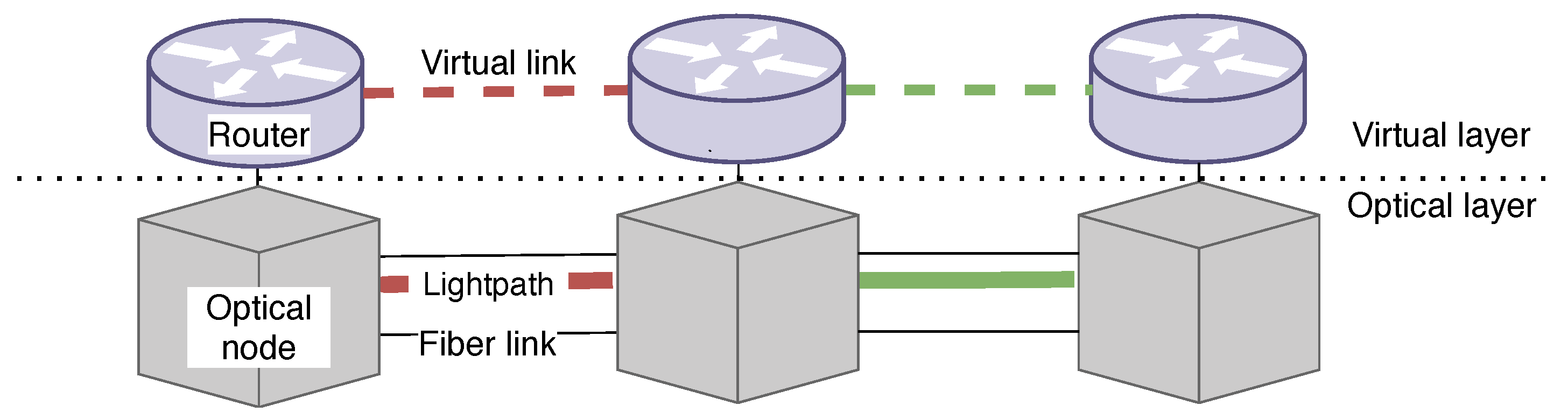
At the beginning, a basic concept of the multi-layer network is introduced. Let us consider a simple multi-layer network architecture comprising two layers: IP (virtual), where all high-capacity IP routers are located, and optical, where optical nodes (cross-connects) are physically connected by fiber links [
14].
Figure 1 illustrates a multi-layer architecture.
The IP layer represents the virtual topology; it is composed of routers connected to each other by virtual (logical) links. Routers are able to groom traffic in the electric domain. Each virtual link is associated with a lightpath. For instance, two lightpaths and corresponding virtual links are shown in
Figure 1. The IP layer aggregates data traffic arriving from the access and metro networks, then routes this traffic over the virtual topology. Since the process of traffic aggregation is a complex problem, it should be investigated separately. This problem is beyond the scope of this paper. However, it is assumed that the volume of traffic in the experiments is a result of traffic aggregation. The main problem assumed in IP is how to route traffic through the virtual topology. Further, it can be seen that routers are associated with optical nodes (see
Figure 1). Considering IPoEON architecture, each IP router port is connected to bandwidth–variable transponders or sliceable bandwidth–variable transponders bound to particular bandwidth–variable optical cross-connects [
15]. Transponders are able to groom multiple traffic streams in the optical domain and perform the add and drop functions [
16]. Furthermore, transponders allow for changing the transmission bandwidth as well as the modulation format. Each one generates independent optical channels. Optical cross-connects are responsible for switching optical channels through the network and setting lightpaths. The problem of setting elastic lightpaths is addressed later.
To provide optical resources in the considered architecture, there are two main approaches; namely, visible (available) resources and invisible (hidden) resources for the IP layer. More specifically, a lightpath that occupies resources visible for IP is called a virtual link, whereas a lightpath that occupies hidden resources is called a bypass. Hence, the optical layer is responsible for setting lightpaths representing virtual links and on-demand bypasses. It is important to mention here that most of the research assumes that the optical resources are fully available in the IP layer. Contrary, in this paper it is assumed that only a part of the physical resources are available for the IP layer. Finally, to manage multi-layer resources, reflect the dynamic changes of the infrastructure, as well as handle incoming network requests, the SDN concept is utilized. SDN uses programmable switches; hence, reconfigurable devices [
17] are assumed in the paper. In the next section, more details according to the SDN concept are given.
3.2. SDN Concept
As the solution proposed in this paper utilizes SDN, we explain some basics about SDN for the facility of the readers. SDN enables a dynamic configuration according to the network conditions; hence, it becomes a more and more popular solution for the implementation of the control plane. In the traditional network (without SDN), each network device has its own control plane. Based on the information gathered from the neighboring devices, each device makes decisions about the forwarding of incoming traffic. It may increase the complexity and unpredictability of the entire network. Contrary, in SDN, network intelligence is (logically) centralized in the SDN controller, which maintains a global view of the network. With the introduction of SDN and its separation of the controlling software from the forwarding hardware, one can easily develop and test a new logic software [
18].
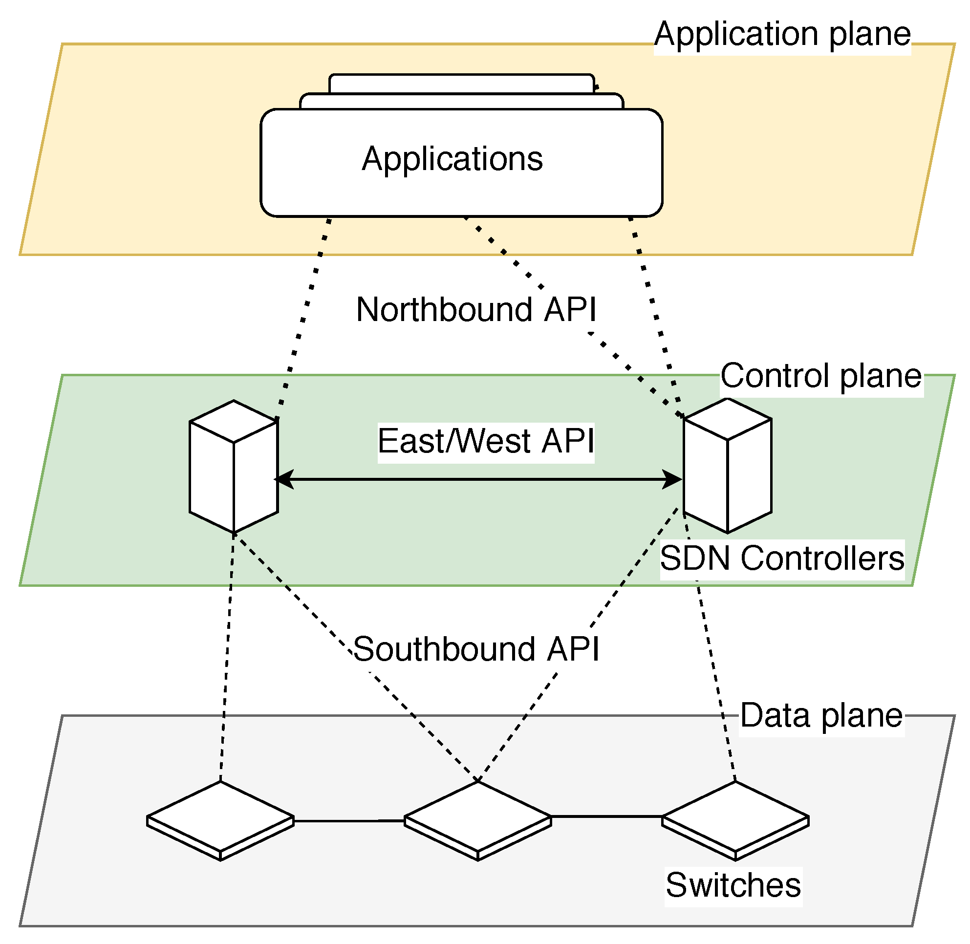
In principle, the SDN concept is based on three major planes: application, control, and data [
19]. An application plane designs rules and policies, which are implemented in programs. These programs make requests for network functions from the control plane and the data plane. The application plane can build an abstracted view of the network and current traffic statistics. A control plane implements rules on data plane devices. This plane is realized by the SDN controller, e.g., the OpenDaylight controller. Finally, a data plane contains physical network elements and elements that form the data path. Communication between both planes is established by using application programmable interfaces (APIs).
Figure 2 presents planes and APIs of SDN [
20].
The following APIs can be identified: northbound API (representational state transfer), east-/westbound API, and southbound API between the control plane and the data plane. Southbound API provides the information of data plane devices to the control plane as well as the instructions or rules from the control plane to data plane devices. For example, the OpenFlow protocol allows direct access and manipulation of the forwarding plane on network devices such as virtual or physical switches and routers.
Generally, the SDN controller maintains a global view of the multi-layer network. More precisely, the controller obtains information about the current utilization of virtual links from the network devices installed in the IP layer and the current utilization of optical links from the network devices installed in the optical layer. It may, therefore, optimize paths for traffic and assign the required resources for transmission. One should note that a problem of resource allocation depends on applied optical transmission [
3]. The next section presents details of the optical layer considered in this paper.
3.3. EON Layer
As mentioned in
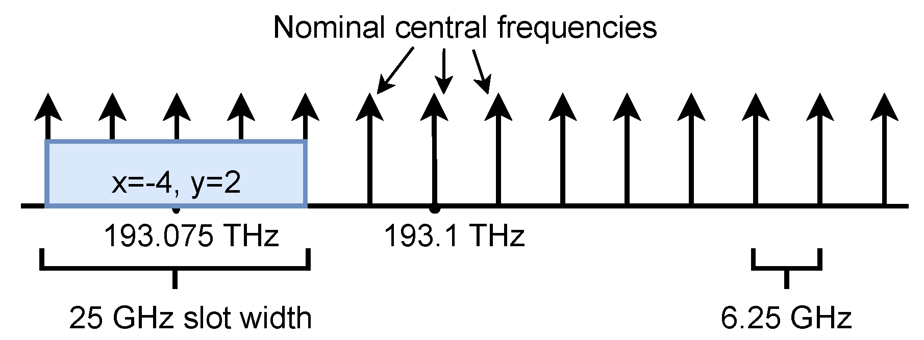
Section 3.1, optical networks are responsible for carrying IP traffic. The following section provides descriptions of the EON layer, which provides resources for multi-layer networks investigated in this paper. In 2012, a flexible grid was introduced as the frequency grid [
2]. The recommendation defines a nominal central frequency granularity of 6.25 GHz and a slot width granularity of 12.5 GHz. The term frequency slot defines a frequency range that can be occupied by a lightpath. Thus, a slot is described by its nominal central frequency and its slot width. The nominal central frequency is equal to
THz, where 193.1 THz is the ITU-T reference frequency for transmission over the C band and
x is the number of 6.25 GHz (positive, negative, or 0). Slot width is constrained to be
GHz, where
y is a positive integer greater than or equal to 1 and 12.5 GHz describes a slot width granularity. An example of a flexible grid with a slot is depicted in
Figure 3.
According to the figure, a slot is described by a nominal central frequency equal to 193.075 THz and a slot width equal to 25 GHz, and x and y are equal to and 2, respectively. It can be assumed that the frequency slot is a set of contiguous slices (the property called the spectrum contiguity constraint).
The width of a slice corresponds to the bandwidth of an orthogonal frequency division multiplexing (OFDM) sub-carrier [
21]. This technology enables the formation of super-channels, which are based on multiple sub-carriers (sub-channels) overlapped in an optical domain. Varying the number of sub-carriers results in changing the transmission bandwidth. Simultaneously, different modulation formats can be used based on linear and non-linear impairment factors. Each modulation format may be characterized by spectral efficiency (expressed in [bit/s/Hz]), which informs about the amount of information ([bit]) that can be sent in a unit of time ([s]) within a unit of bandwidth ([Hz]). The higher the value of spectral efficiency, the more efficient a modulation format. Accordingly, the high value of spectral efficiency means that fewer resources are occupied; however, the maximum distance range supported for modulation format is shorter. As shown in [
22], the modulation format may be chosen based on transmission distance; hence, a low-bit rate modulation format is used for longer transmission distances, whereas a high-bit rate modulation format is preferred for shorter transmission distances.
Summarizing above, it can be seen that optical connections in the EON layer occupy such an amount (a set of contiguous slices) of the spectrum as needed at a required bit rate restricted to transmission requirements.
4. Notation
In general, a network topology can be modeled as a graph with possible additional constraints, such as a number of slices or a link capacity. Specifically, the topology of the network is defined by , where is the set of nodes and is the set of links, e.g., fiber links and virtual links. The request d is defined by , where s is the source node of the request and t is the destination node of the request. represents the requested bandwidth (bit rate) between end nodes s and t. It should be noticed that d in the virtual layer denotes the requirement for bandwidth, whereas d in the EON layer is the request for setting the lightpath. Each lightpath represents path p and optical spectrum with a width equal to the number of slices . The width depends on the requested bandwidth, applied to the transmission model. The transmission model can be considered as the set of possible modulation formats , each being characterized by the spectral efficiency and corresponding maximum transmission distance range for the assumed width of slice . The request d is defined by , where s is the source router of the request and t is the destination router of the request. represents the required bandwidth (bit-rate) between nodes s and t.
5. Elastic Optical Lightpaths
To provide optical transmission between end nodes according to a flexible grid and utilizing multi-carrier modulation formats, an optical connection (a lightpath) should be set up. This requires the allocation of optical resources (in terms of a number of adjacent slices) along links composing an end-to-end path. However, possible solutions to set up lightpaths named routing and wavelength assignment (RWA) algorithms, used in WDM networks, are no longer valid in EON [
23]. It is because RWA solutions do not consider the contiguous allocation constraint and different modulation formats. Therefore, new algorithms are introduced; namely, routing and spectrum allocation (RSA) algorithms [
24,
25]. Additionally, when an RSA algorithm considers the selection of different modulation formats, then this is called a routing modulation format and spectrum allocation (RMSA) algorithm.
Algorithm 1 shows a pseudocode describing the RMSA strategy. It is assumed that the actual state of the EON layer is given. The considered algorithm first finds a feasible path with a determined modulation format and then allocates a required number of slices. The algorithm is called a two-step strategy [
26]. Routing is realized using fixed path sets, containing
k shortest paths.
| Algorithm 1 Pseudocode for describing the RMSA algorithm |
Input: New ;
- 1:
- 2:
for do - 3:
- 4:
if then - 5:
- 6:
if then - 7:
- 8:
- 9:
return // Successful allocation - 10:
end if - 11:
end if - 12:
end for - 13:
return // Blocked request
|
When a new demand
d requesting
arrives, the set of
k candidate paths
for
d is computed. Then, candidate paths
are sorted based on a path selection policy (line 1). Starting from the first of the paths, candidate paths proceed to verify if the allocation is possible. For a particular path, the modulation format
m is tried to determine (line 3). If the modulation format is chosen (line 4) for that modulation format, the number
of free slices required for allocation is calculated (line 5). To determine modulation format
for a particular path
p, expected path length
and the maximum distance range of each modulation format
are compared. This means that the sum of link lengths
(composing the path) cannot exceed the transmission distance of modulation
selected for this path
. Without a loss of generality, it is assumed that the more spectrally efficient the modulation format is, the higher the spectral efficiency achieved. Since spectrum utilization is minimized, the most spectrally efficient format suitable for distance is chosen. After determining modulation format
m, the number of adjacent slices (
) required to handle bandwidth demand
between two nodes
s and
t along considered physical path
p is calculated similarly as presented in [
27,
28]. The
is calculated as:
, where
[Gbit/s] denotes requested bandwidth;
[bit/s/Hz] is the spectral efficiency of
m utilized on
p;
[GHz] denotes the width of frequency slice;
is the number of slices for guard band needed to separate adjacent optical transmissions. Next, the analysis of the path covers the search for an available set of
slices. The set of slices must satisfy continuity, contiguity, and non-overlapping constraints along links composing a path. If the allocation is possible on a particular candidate (line 6), then the spectrum allocation procedure is executed (lines 7 and 8).
Since more than one such set can exist, the spectrum allocation policy answers the question of how to allocate slices across specific links (see [
29]). Spectrum allocation policy selects (indicates first slice in the set) a set of
contiguous slices along determined path
p (line 7) and allocates it (line 8). This means that, starting from selected
, contiguous slices are allocated along a determined path. Then, the RMSA strategy ends success, and
is returned (line 9). If all candidate paths were examined and there is no feasible path, the request is blocked (rejected) and the solution returns
(line 13). Obviously, if the available path for allocation does not exist, the spectrum allocation step is not performed. Note that the presented algorithm does not consider regeneration in a network.
6. Automatic Hidden Lightpaths
Considering the IPoEON architecture and dynamic network scenario, the main problem is to find resources to provision requests. Moreover, a key challenge is to develop a simple solution for a multi-layer network. In this section, we explain a concept of diversification of resources and then propose AHLs. Based on an example, we explain the AHLs in IPoEONs in detail. Finally, we describe a common scenario (denoted as reference one).
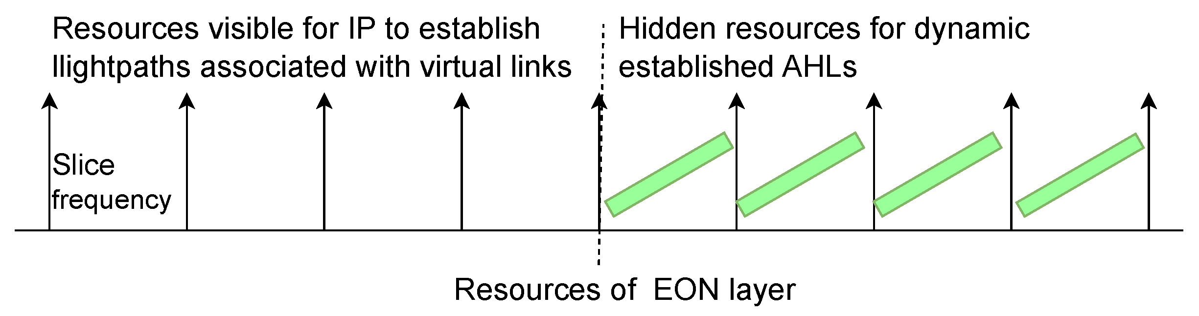
A significant difference introduced in the paper is to reveal to the IP layer only selected optical resources (in terms of the number of slices). The remaining spectrum, denoted as hidden resources, can be used when congestions occur.
Figure 4 shows the diversification of resources. It is assumed that the amount of hidden resources might be at most equal to the amount of resources visible for the IP layer.
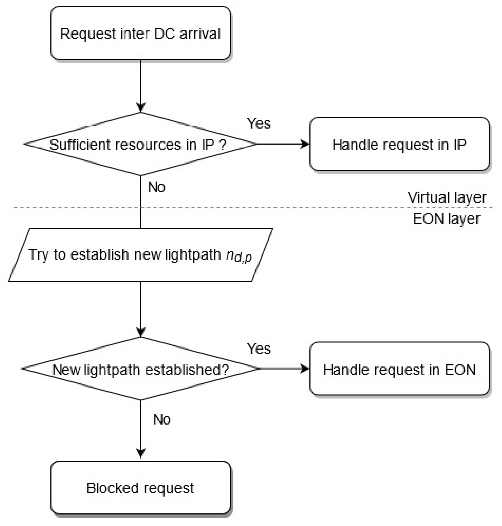
In the following, we introduce the AHL aimed at utilizing resources effectively and reducing rejected traffic. The proposed AHLs are fully compatible with the SDN concept. The algorithm starts on a new demand (request)
d arrival. The network topology and the current state of the network are known by the controller. The controller verifies if sufficient resources are available. Firstly, the SDN controller estimates resources in IP. The rationale is to maximize the utilization of resources available at the virtual layer (as is well-documented in [
30]). To solve routing in the IP (to route traffic between
s and
t), the single shortest path is determined. If sufficient resources are available, then the request is served in that layer and the algorithm ends. If requested bandwidth cannot be guaranteed in an IP layer, then the SDN controller tries to utilize the EON layer [
3]. In the EON layer, hidden resources are expected to handle the new demand. What is important, the RSA/RMSA method is implemented in this layer. For the purpose of traffic provisioning, the requested bit rate
is translated to the number of frequency slices
. If the setting of an AHL is possible, then hidden resources are allocated and the strategy ends. When the EON layer also fails to handle the demand, the request is blocked.
Figure 5 shows the steps of the AHL algorithm.
Once again, it should be stressed that all presented algorithms are fully compatible with the SDN concept regarding the network control architecture. When a request appears in a network, the network controller checks the possibilities of allocation and makes the decision about it.
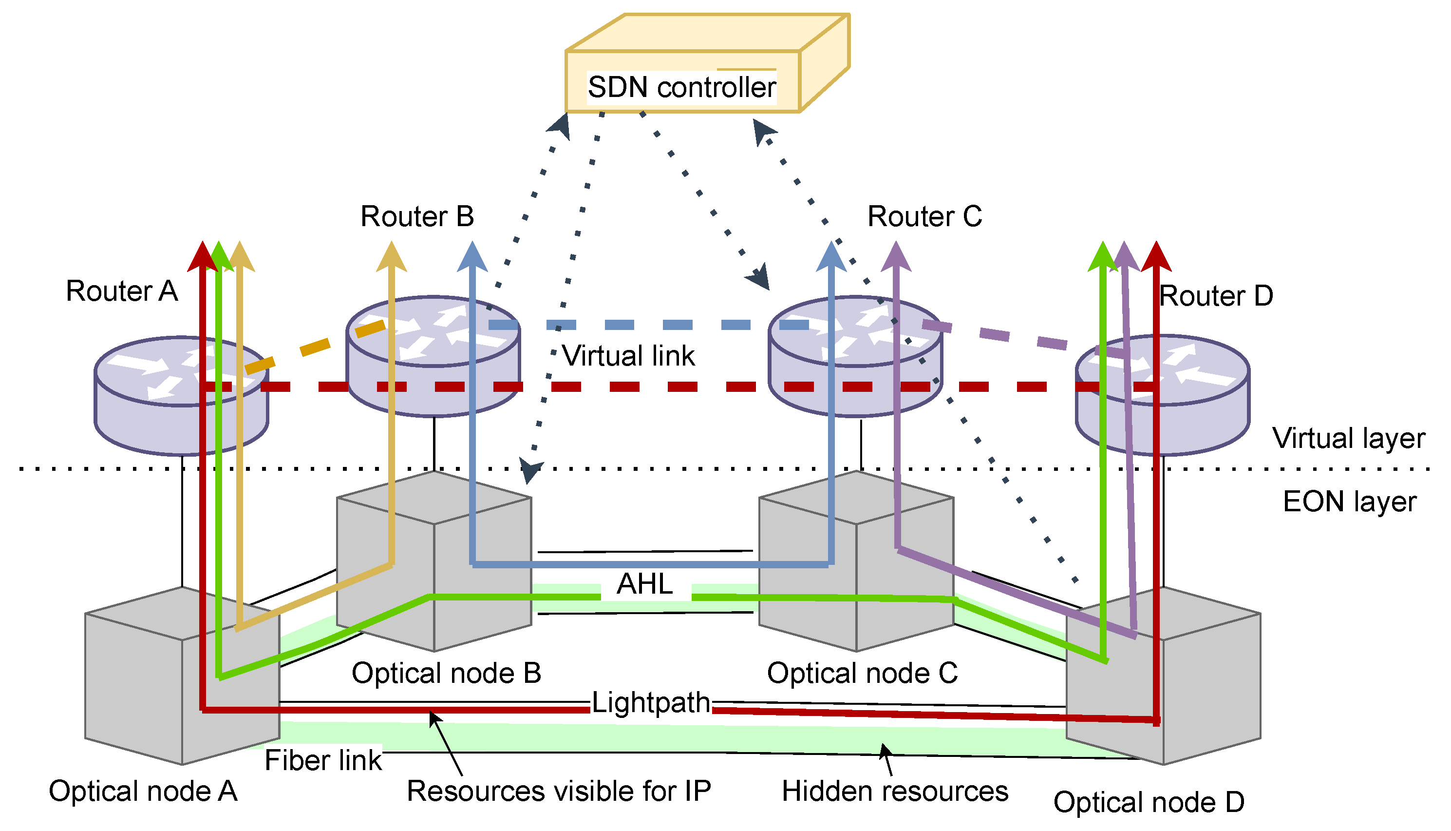
Figure 6 shows a simple network architecture of SDN-based IPoEON with AHL established.
This figure explains the difference between lightpaths associated with virtual links and AHLs. The diversification of resources is introduced for each fiber link, and the white and green colors of resources denote resources available for IP and hidden resources, respectively. As can be seen, lightpaths utilizing resources visible for the IP layer are reported as virtual links between routers, e.g., lightpaths between nodes A–B (solid yellow line), B–C (solid blue line) handle virtual links between routers A–B (dotted yellow line), B–C (dotted blue line), respectively. A lightpath between nodes A–D through B and C (solid green line) is an AHL since it allocates a hidden spectrum. For example, in case of congestion in the IP layer on virtual link A-B, an AHL A-D-C-B may be established to offload the new traffic (incoming request). Such an AHL is established to offload traffic, but a new virtual link is not reported in the IP layer. When transmission handled by the AHL ends, resources are released.
Figure 5.
Diagram of the proposed AHL algorithm.
Figure 5.
Diagram of the proposed AHL algorithm.
Figure 6.
Example of lightpaths associated with virtual links and AHLs.
Figure 6.
Example of lightpaths associated with virtual links and AHLs.
Finally, it should be highlighted that proposed solutions not only deal with optical resource computations and their technology constraints (e.g., spectrum continuity and contiguity) but also consider the packet network topology. Established flexigrid optical connections derive virtual (packet) links that inherit attributes (e.g., available bandwidth and accumulated delay) from their underlying (optical) connections.
6.1. SPF FF-Based AHLs
To set up AHLs, we adapted the Shortest Path First (SPF) First Fit (FF) spectrum allocation based on
k set paths to the RMSA. It means that the sets of
k candidate paths are fixed for each node pair of nodes in a network. The candidate paths are calculated using the
k-shortest path algorithm with a link length (given in kilometers) and paths
are sorted in ascending order based on physical length. Algorithm 2 presents pseudocode describing the SPF. For each path, length
is calculated (lines 1 and 2). Next, all paths in the set are sorted in ascending order based on physical length. As a result, each path
meets condition
(line 4). Then, the set of sorted paths might proceed in the next stages of RMSA (see Algorithm 1 in
Section 5). Along the selected path, the spectrum is assigned according to the first fit policy. This policy allocates a request in the first feasible, available set of frequency slices along a path [
31].
| Algorithm 2 Pseudocode for describing the SPF |
Input:
- 1:
for each do - 2:
- 3:
end for - 4:
∧
|
6.2. Common Scenario
Finally, it can be noticed that in a common scenario, all resources are visible for IP and used to provide virtual links. Each lightpath is then abstracted in the IP layer as a virtual link and traffic is routed through the virtual layer. Typically, network operators implement a single path in the virtual layer.
7. Materials and Methods
Since traffic sent between DCs is an important issue that puts pressure on network operators, such traffic should be investigated. Simulations are a perfect tool to increase knowledge of the studied system. Therefore, there is no need to execute the simulation in real time. To provide insight into the performance of AHLs, many simulations were performed. Following the description of simulation tools, topology networks are provided. We present details for the optical layer and then the virtual layer, which is set up under the optical layer. Finally, we present a traffic scenario prepared for simulations and a metric proposed to asses AHLs.
7.1. Simulation Details
The simulations were performed with OMNeT++ [
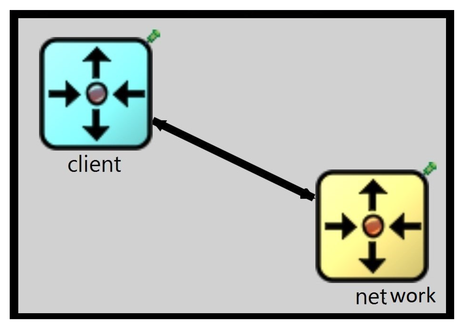
32]. OMNeT++ is an object-oriented modular discrete event simulation framework, and it was used in order to create a simulator of the problem studied in this paper. OMNeT++ was selected because it is an OpenSource software and provides very good API allowing the creation of scalable discrete event simulations. The simulation cases and architectures have been developed in the OMNeT++ version 5.7 Academic Edition, under Academic Public License, using C++11 with BGL 1.53.0 and Xerces-C++ 3.1.1 libraries. The simulator is organized into a number of modules representing either logical or physical elements. Particularly, the simulator consists of modules representing “client” and “network” linked in a bidirectional way.
Figure 7 shows a screen printed from OMNeT++.
The modules were written in the internal OMNeT++ language NED. The “client” module generates connection requests and determines when the transmission is ended. The “network” module stores information about the topology, network resources, and paths. It is responsible for processing the requests in the network; it releases and allocates resources and implements algorithms to service requests. These algorithms were written in C++. Firstly, we implemented RMSA in the EON layer, and secondly, we focused on the implementation of the IP layer. Finally, IP and EON were joined in a multi-layer network. All the simulation runs were provided with stable and fully implemented versions of IPoEON.
Figure 7.
Model of client network.
Figure 7.
Model of client network.
7.2. Network Topology
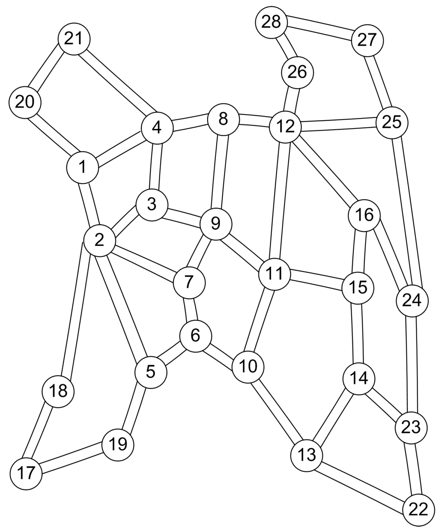
We performed simulations in the Euro28 network (28 nodes, 82 directed links), which is described in detail in [
33];
Figure 8 shows the Euro network.
Figure 8.
The Euro28 network.
Figure 8.
The Euro28 network.
Table 1 provides detailed parameters of network topology; namely, the number of nodes, the number of links, minimum, maximum, and average node degree, and average link length of network topology. It can be noticed that in the Euro28 the average nodal degree is equal to 2.9 and the average link length is 625.365 km.
The localization of designated nodes in the network was determined according to the topological method (based on information about physical network topology). Particularly, two methods were considered; namely, the nodal degree and length of the shortest path to any other network node [
34]. The former associates nodes with nodes of the highest nodal degree
. The latter associates nodes with the lowest value of the average length of the shortest path to any other network nodes
. The following nodes were selected in simulations:
for ;
for .
For the Euro28 network used in simulations, the sets of
k candidate paths were calculated and nodes to generate dynamic requests were selected. The candidate paths for each node pair were calculated using the
k-shortest path algorithm with a link length (given in kilometers). Paths were ordered in increasing value of their length and the first
k paths were used for simulations. To set up AHLs, we adapted to the RMSA SPF FF based on
k set paths (see
Section 6.1). This means that the sets of
k candidate paths are fixed for each pair of nodes in the network. The candidate paths were calculated using the
k-shortest path algorithm with a link length (given in kilometers). Paths were ordered in increasing value of their length and first
k paths were used for simulations. We investigated
to set up lightpaths.
7.3. Optical Layer
In the optical layer, we utilized a flexible-grid optical spectrum and different modulation formats. The following parameters in the EON layer were set up. The optical spectrum of each link was divided into 320 frequency slices, each having a width of 12.5 GHz [
2]. To separate neighbor connections, one slice was used as a guard band. The transmission model assumed in simulations was based on the “half-distance law” presented in [
35]. Particularly, four modulation formats: BPSK (binary phase-shift keying), QPSK (quadrature phase-shift keying), 8QAM (8-quadrature amplitude modulation), and 16QAM (16-quadrature amplitude modulation) were considered. The supported transmission distances and spectral efficiency for BPSK, QPSK, 8QAM, and 16-QAM, were 9600 km and 1 bit/s/Hz 4800 km and 2 bit/s/Hz, 2400 km and 3 bit/s/Hz, 1200 km, and 4bit/s/Hz, respectively.
Table 2 describes parameters for modulation formats including transmission range, spectral efficiency, and bit rate per slice for each modulation format.
The same assumptions are taken in [
28,
36,
37]. It should be noted that the applied transmission ranges of modulation formats allow us to set up long lightpaths without regeneration in the networks. For a given path length, the most spectrally efficient modulation format was chosen. Then, path selection and spectrum allocation policies were utilized to set up lightpaths.
7.4. Network Layer
In the network layer, routers are able to groom traffic in the electric layer. Simultaneously, full flexibility is assumed in a sense that each router port is connected to a sliceable transponder able to groom multiple traffic streams in the optical domain [
38]. The topology of the virtual layer was established. Each directed virtual link was created by the lightpath which occupied resources visible for IP. The topology of the virtual layer was the same as the physical topology. The virtual topology was static and did not change during simulations. It was known in advance which lightpaths were needed. Based on the assumed transmission model (see
Table 2) and physical parameters of topology (such as length of links), the 16QAM modulation format was utilized/chosen along with 76 lightpaths and 8QAM for 6 lightpaths which occupied resources visible for IP. The capacity of virtual links
comprising
slices was calculated as:
, where
is the number of slices for guard band,
[bit/s/Hz] is the spectral efficiency of
m utilized on lightpath;
[GHz] denotes the width of frequency slice. In a common (reference) scenario, virtual links were associated with lightpaths which occupied 320 of the slices (all optical resources were visible for IP). In cases of AHLs, virtual links were associated with lightpaths which occupied 160 slices (160 slices were visible for IP, whereas 160 slices were hidden for IP and available for AHLs). The selection of 160 slices as hidden slices was based on the results of numerous simulations presented in [
10,
11].
In the IP layer, the OSPF protocol was used for routing purposes. This routing protocol uses Dijkstra’s algorithm to find the shortest path from a source node to a destination node. To avoid the saturation of links, the congestion threshold th was introduced. If the usage of a particular virtual link’s capacity is below or equal to th, then the virtual layer handles arriving demands. A value for the threshold th was selected based on the extensive analysis of the results obtained under different values of those thresholds. For the selected values of th, results obtained for the AHLs always provide a significant improvement in comparison to the reference approach. The best results were achieved when th was set to 0.7.
7.5. Traffic Scenarios
We prepared a scenario assuming long-lived traffic, referred to as background traffic, and dynamic requests generated between designed nodes in the network referred to as dynamic requests. In other words, two types of traffic were assumed. The first traffic type was long-lived background traffic between each pair of nodes with a bitrate equal to 50 Gbit/s. The amount of traffic was selected in such a way as to ensure that a link was close to congestion. For example, when 160 slices were used to establish virtual links, the most loaded link in IP utilized approximately 67% of link capacity in the EURO28 network. This allowed us to analyze AHLs in a near-real environment. Background traffic was always served in the virtual layer utilizing OSPF. This traffic was sent over virtual links allocating 320 slices for the common scenario, or 160 slices for AHLs. The second traffic type was dynamic requests (traffic bursts), generated by nodes designated in the network according to the topology-based methods [
34]. The efficiency of the proposed AHLs was validated throughout numerous simulations performed for two networks under scenarios with traffic bursts generated between selected nodes. It was reasonable to investigate such scenarios since popular services are based on communication with special servers that are mostly located in selected nodes. For each pair of designed nodes, requests were uniformly distributed between 50 Gbit/s and 1 Tbit/s with a 50 Gbit/s step (with average value of 525 Gbit/s) [
39].
Dynamic requests arrived one by one to the network with an exponentially distributed inter-arrival time and mean value
and an exponentially distributed holding time
. Therefore, the traffic load was computed as
Erlangs. In order to simulate different network conditions, the mean value of
was changed in a step manner whereas
remained constant. For each value of traffic load, the first 5000 requests were ignored to achieve steady-state. After that, another
requests were evaluated [
40]. The simulations have been performed in the OMNeT++ simulator.
7.6. Metrics
Various parameters were collected during each simulation. The performance indicators of AHLs were bandwidth blocking probability (BBP) and overall spectrum occupation. The metrics were calculated with respect to requests generated dynamically. The BBP is defined as the total bandwidth of all blocked demands divided by the total bandwidth of all demands (accepted or rejected).
8. Results
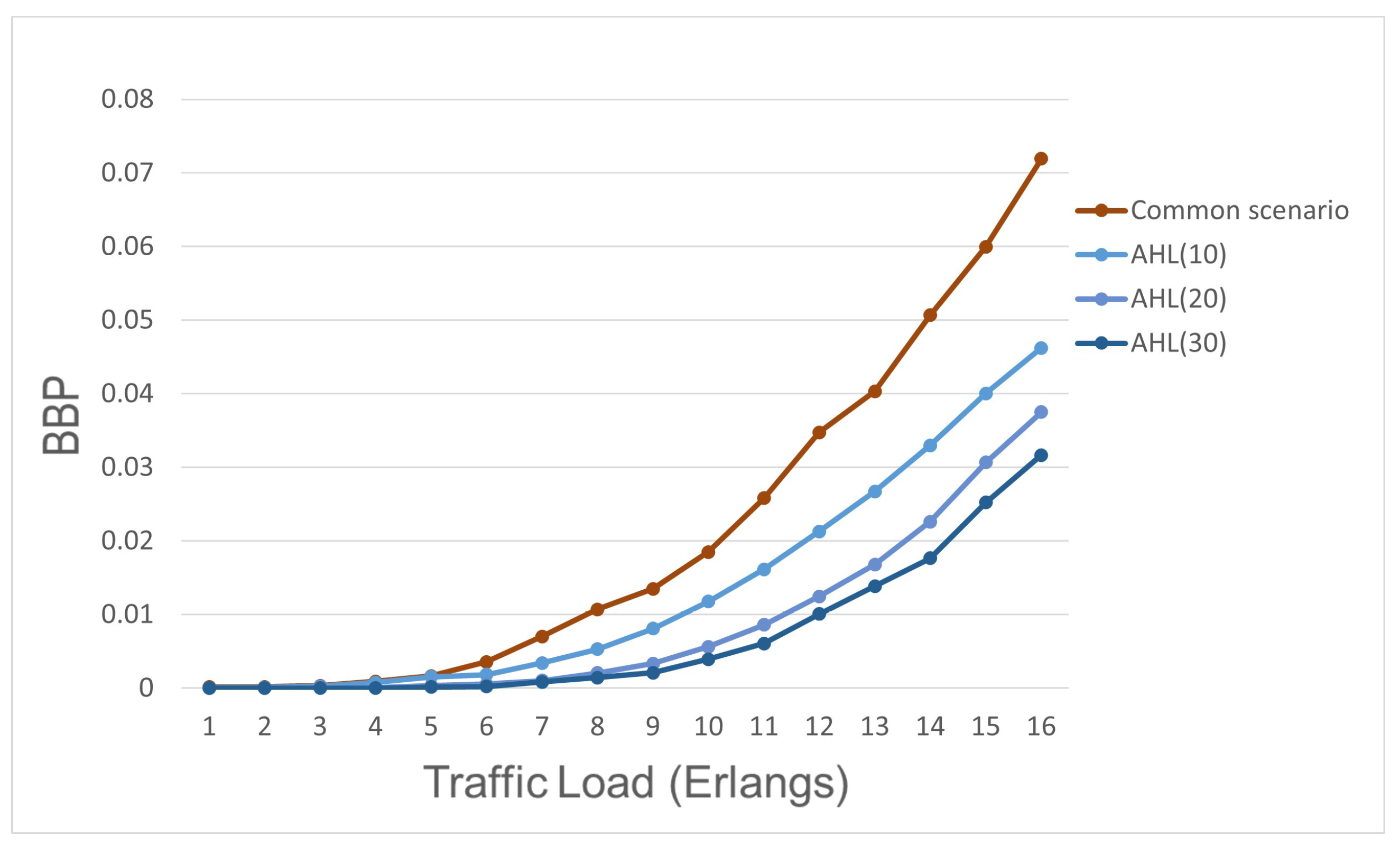
Results of simulation experiments that show the usefulness of the proposed solution for dynamic inter-DC traffic in multi-layer networks are presented in this section. The mechanisms are separately analyzed in the Euro28 network for a particular DC placement scenario. The goal of the numerical experiments reported in this section is to assess the performance of AHLs in the SDN-based multi-layer network. Particularly, the performance of AHLs for different k sets of candidate paths was analyzed. AHLs were evaluated and experiments were made for k = 10, k = 20, and k = 30 candidate paths. The main goal of numerical experiments was to compare the performance of AHLs against the common scenario (all resources visible for IP, and AHLs were not utilized at all). Moreover, the performance of AHLs for various numbers of candidate paths was investigated.
Figure 9 presents performance indicator (BBP) for all of the strategies in function of the traffic load under scenario
.
Based on this figure, the following conclusions can be drawn. The common scenario (all resources were visible for IP) provides the worst performance in terms of BBP when compared to all AHLs. That is because the reference case assumes all resources for IP and these resources are utilized by only a single path in the virtual layer. Therefore, there is no possibility to provide additional resources when congestions occur. According to the results obtained for the AHL(10), AHL(20), and AHL(30), it can be noticed that the increasing number of candidate paths improves the performance of the AHL approach. When the number of candidate paths increases, more lightpaths can be established. Consequently, more AHLs can be provided to omit congested links in the IP layer. Thus, AHLs for case 30 of candidate paths achieve the best reduction in BBP. However, as the number of candidate paths increases, the complexity and execution time of the algorithm might increase. Especially, it is important if a large network is analyzed.
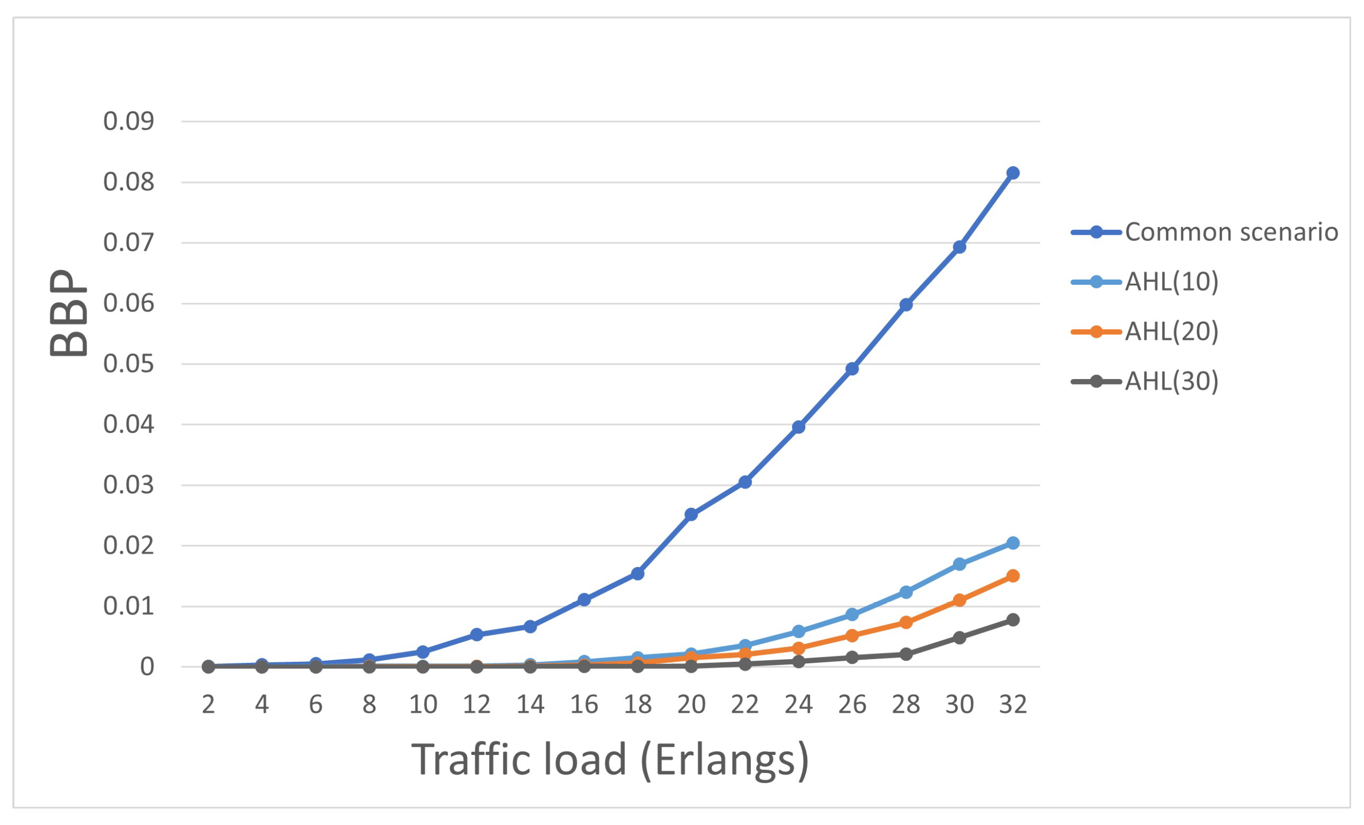
Figure 10 presents performance indicator (BBP) for all of the strategies in function of the traffic load under scenario
.
Based on the figure, the first clear conclusion is that all AHLs provide lower BBP compared to the case when all resources are visible for IP (denoted as a common scenario). This results from the fact that the AHL approaches give the opportunity to consider various paths for sending traffic between nodes in the network. Analyzing results for consecutive cases—10, 20, and 30—candidate paths, it can be seen that BBP reduction gain is higher when more candidate paths are utilized for AHL, regardless of the load. When the number of candidate paths increases, more lightpaths can be established and BBP decreases. An increasing number of paths allows for utilizing links not previously used and the network load is distributed over the network evenly. Consequently, the AHL(30) approach achieves a better reduction in BBP when compared to the AHL(10) and AHL(20) approaches. This confirms previous findings. The next sections provide a discussion and conclusions of our findings presented in this paper.
Figure 10.
BBP in function of the traffic load under scenario .
Figure 10.
BBP in function of the traffic load under scenario .
9. Discussion
The concept of AHLs includes stages corresponding to each layer. The network layer handles demands using resources available in the virtual layer. Alternatively, in case of resource depletion, hidden resources are used to handle demands. In the virtual layer, single-path routing (OSPF protocol) was used; simultaneously, the two-step RMSA solution was adapted to set up AHLs. The solution comprises a path selection policy and selection of the most spectrally efficient modulation format suitable for a distance and FF spectrum allocation policy. To select paths (in terms of links) for AHLs we used the SPF-based path selection policy as one of the most popular policies. Various candidate paths were considered for SPF FF-based AHLs. AHLs were also compared to common scenarios in which optical resources were fully visible for the IP layer and AHLs were not utilized at all. Simulation results indicate that all AHL approaches provide improvements in terms of bandwidth blocking probability in comparison to the reference approach. In addition, the AHL(30) approach achieves better reduction in BBP compared to AHL(10) and AHL(20) approaches. In conclusion, AHLs can absorb unexpected traffic load fluctuations and deal with congestion when resources in the network layer are not sufficient to service requests. Simultaneously, AHLs in multi-layer networks provide resource savings. By minimizing the possibility of discarding traffic, the amount of all resources used does not actually increase.
There are some limitations that we consider for future works. For example, different node selection scenarios for dynamic traffic generation. In this paper, we consider only two scenarios of the selection of nodes to generate dynamic traffic. It covers only some parts of the network. The results would vary if a different set of nodes would be selected. Furthermore, several more issues can be addressed in future studies. Firstly, planning strategies to optimize virtual topology can be designed. Secondly, existing traffic can be rerouted and sent through newly established AHLs to retrieve the capacity of virtual links. Thirdly, the scenario of recovery disaster can be considered and crucial traffic should be routed through lightpaths utilizing hidden resources. Eventually, spatial–spectral resources might be hidden and then utilized to establish offloading lightpaths.
10. Conclusions
In cases of network congestion, efficient resource allocation in IPoEONs is significantly challenging compared to fixed-grid DWDM networks due to increased flexibility in IPoEON architectures. In this paper, we developed a new method to provide additional resources for emergency situations in IPoEON networks. Modern telecommunication networks are expected to ensure additional resources to handle traffic spikes originating from emergency circumstances. Hence, the AHL-based solution may be used by network operators to avoid link congestion as well as to save resources. Moreover, AHLs are transparent to the network layer since the diversification of resources is introduced. Therefore, the routing tables in routers do not need to be updated when new AHLs are created. It makes our solution more attractive for network operators. The results obtained by us by conducting carefully selected simulation experiments confirm that AHLs improve bandwidth blocking probability in a network. It is important for operators and end users because the network is able to handle more traffic with satisfactory quality. It is especially important in cases when something unexpected occurs and it is necessary to send more traffic (more than usual) in a short time. Finally, our solution is fully compatible with the SDN concept; thus, it can be implemented in the SDN control plane to effectively utilize the resources of multi-layer networks.


