1. Introduction
Ashkin blazed the trail in exhibiting the successful laser trapping of micrometer-sized dielectric particles through the deployment of two counter-propagating beams [
1]. This approach proposes that a strongly focused laser beam can create a stable 3D trap, referred to as optical tweezers [
2], which have revolutionized the field of optical trapping. Optical tweezers have been employed for a vast array of purposes, such as non-invasive handling of filaments and organelles within living cells [
3,
4], examination of bacterial trapping [
5], biomolecular systems, and investigation of molecular motors such as kinesin [
6] and myosin [
7]. Nevertheless, the issue of trapping particles smaller than the wavelength of light persists due to the light diffraction limit.
A surface plasmon polariton (SPP) as an electromagnetic field existing at the interface between a metal and a dielectric material has the characteristics of surface limitation and sub-wavelength. These characteristics make the SPP promising in areas involving environment, energy, biology, and medicine [
8]. Plasmonic tweezers have recently arisen as a possible means of downsizing conventional optical trapping to the subwavelength domain. Recently, research has been attracted to the potential of plasmonic optical trapping and its applications [
9]. For example, plasmonic nano-antennas were used to trap 200 nm polystyrene particles using only 300 mW/μm
2 of illumination power [
10]. Similarly, 110 nm polystyrene beads were trapped and rotated using plasmonic nanopillars with an illumination intensity of just 10 mW/μm
2 [
11]. A new form of photonic crystal nano-tweezer was used to trap and release 22 nm polymer particles with a laser power ∼11 mW [
12]. A plasmonic nanocavity was even utilized to trap 20 nm polystyrene particles through a self-induced back-action mechanism while keeping the illumination power low at below 10 mW [
13]. In the realm of biosciences, individual bacteria were trapped by optical tweezers based on photonic crystal cavities [
14], streptavidin molecules were trapped by a single coaxial aperture with a laser power as low as 4.7 mW [
15], and even a single DNA molecule was trapped by a circular nanohole created on a Au substrate with an incident power 7.8 mW [
16] and by a double-nanohole in a Au film using a low laser power of 3.5 mW [
17]. Although previous studies have demonstrated the potential of SPP tweezers for trapping small particles with high optical forces at low illumination power, most SPP tweezers suffer from high thermal effects that could undermine biological samples. Dielectric configurations and waveguides are alternative options [
18,
19,
20] that can mitigate the thermal effect, but they often come at the cost of reduced optical force [
18], or increased device volume [
19,
20]. Therefore, the effective and simple manipulation of tiny nanoparticles with SPP configuration remains highly significant.
At present, a variety of micro-nano structures are used to generate plasma optical tweezers for nano-particle capture and manipulation, such as C-shaped nano aperture [
21], T-shaped [
22], and bowtie shaped [
23] nano-antennas, non-concentric nano-rings [
24], nanopillars [
25], Archimedean spirals [
26], and plasmonic metamaterials [
27,
28]. Compared with these complex structures, annular slits can also be used for the excitation and focusing of SPPs, which are simpler to design and prepare [
15,
29], and the flat metal substrate facilitates heat dissipation and reduces thermal effects. Therefore, it is an alternative to complex micro/nano structures to form optical tweezers. In addition, the annular slit has rotational symmetry and is suitable for excitation by a variety of vector light fields, including one or more sets of symmetrical linearly polarized beams and radially polarized beams. Upon being stimulated by vector light fields, the annular slit structure enables various particle trapping techniques, such as trapping, moving, and rotating particles, and ease of control through phase manipulation facilitated by a liquid crystal spatial light modulator (SLM), without requiring any changes in wavelength.
This study examines the particle trapping performance of the metal annular slit when excited by linearly polarized beams and radially polarized beams. These two vector light fields were chosen for their compatibility with the annular slit and ability to effectively excite surface plasmons, providing the flexibility to regulate and enhance particle trapping. When excited by a set of linearly polarized beams, the annular slit can provide flexibility performance in particle regulation. The rotation and movement of captured objects can be controlled by changing the position and phase difference of the incident beams. When excited by a radially polarized beam, the annular slit provides a higher intensity SPP focus compared to linear structures of the same size [
30,
31,
32], resulting in enhanced trapping stability. These properties make the annular slit useful for a wide range of applications, such as particle screening, biopharmaceutical applications, medical manipulation, and so on.
Finally, both the optical force and trapping potential are evaluated quantitatively based on the electric and magnetic field obtained by finite difference time domain (FDTD) simulation to demonstrate the validity of the proposed technique.
2. Calculation of Optical Forces in the Surface Plasmon Polariton Field
The Lorentz force method is widely used in the calculation of optical forces when the dipole approximation is valid. This method is known for its remarkable efficiency. If a particle is much smaller than both the wavelength of light and the characteristic length of the electromagnetic field, it satisfies the conditions for Rayleigh scattering, and the optical forces can be estimated by treating the particle as a point dipole [
33]. Metal particles exhibit strong light scattering and light absorption, making them susceptible to gradient force, scattering force, and absorption force in the surface plasmon polariton (SPP) fields. The gradient force for a Rayleigh metal particle with a radius of “
a” can be represented by the following equation [
33,
34]:
where
is the dielectric constant of the free space,
is the polarizability of the metallic particles given by
, with
and
representing the dielectric constants of the metallic particle and the ambient, respectively. The scattering force and absorption force can be written as
where
is the refractive index of the ambient,
is the time-averaged Poynting vector,
and
are the scattering and absorption cross-section, respectively, where
is the wave number of the ambient, and c is the speed of light [
35]. The radiation pressure including scattering force and absorption force can be expressed as
Typically, the interaction between radiation pressure and gradient force determines the outcome of optical trapping [
2]. The gradient force is proportional to the intensity gradient of the electromagnetic field, while the radiation force points in the direction of light propagation. However, in the surface plasmon polariton (SPP) fields, the SPP waves are restricted to a nano-scale region in the vertical direction and propagate toward the center of the SPP focus in the horizontal direction [
36]. As a result, the SPP focus not only exerts a strong vertical gradient force on the particle attracting it to the metal surface, but also a horizontal resultant force of strong gradient force and weak radiation force pulling the particle toward its center.
The trapping potential in the optical field determines the stability of the trap, which refers to the energy needed to move particles from the optical trap to the infinite. Thus, the trapping potential of a particle located at ‘
r0’ from the center of the optical well can be obtained from the force distribution, by the expression [
37]
where
is the radial optical force and is the result of the gradient force and the radiant force. Theoretically, the particle delocalization caused by Brownian motion can be overcome when the trapping potential reaches 1 k
BT. However, to achieve stable capture, the potential well is revquired to reach 10 k
BT [
2,
37], where kB is the Boltzmann constant (1 k
B = 1.3806488 × 10
−23 J/K) and T is the absolute temperature in the trap, which is 300 K at room temperature. Here, it is worth noting that Equation (5) is only valid for conservative forces. For non-conservative forces, Helmholtz–Hodge decomposition needs to be used to formulate the potential [
38].
3. Simulation, Results, and Discussion
In this section, the particle trapping abilities of the annular slit when excited by various vector light fields are analyzed. The simulation study was completed by a commercial Lumerical FDTD software. The electromagnetic fields of the nanostructure were computed using the finite difference time domain (FDTD) method and the optical forces generated by the electromagnetic field were calculated through the dipole approximation method. The target particle was a gold particle with a radius of 35 nm (having a dielectric constant of εAu = −4.29002 + 1.64259i) surrounded by water with a refractive index of 1.338.
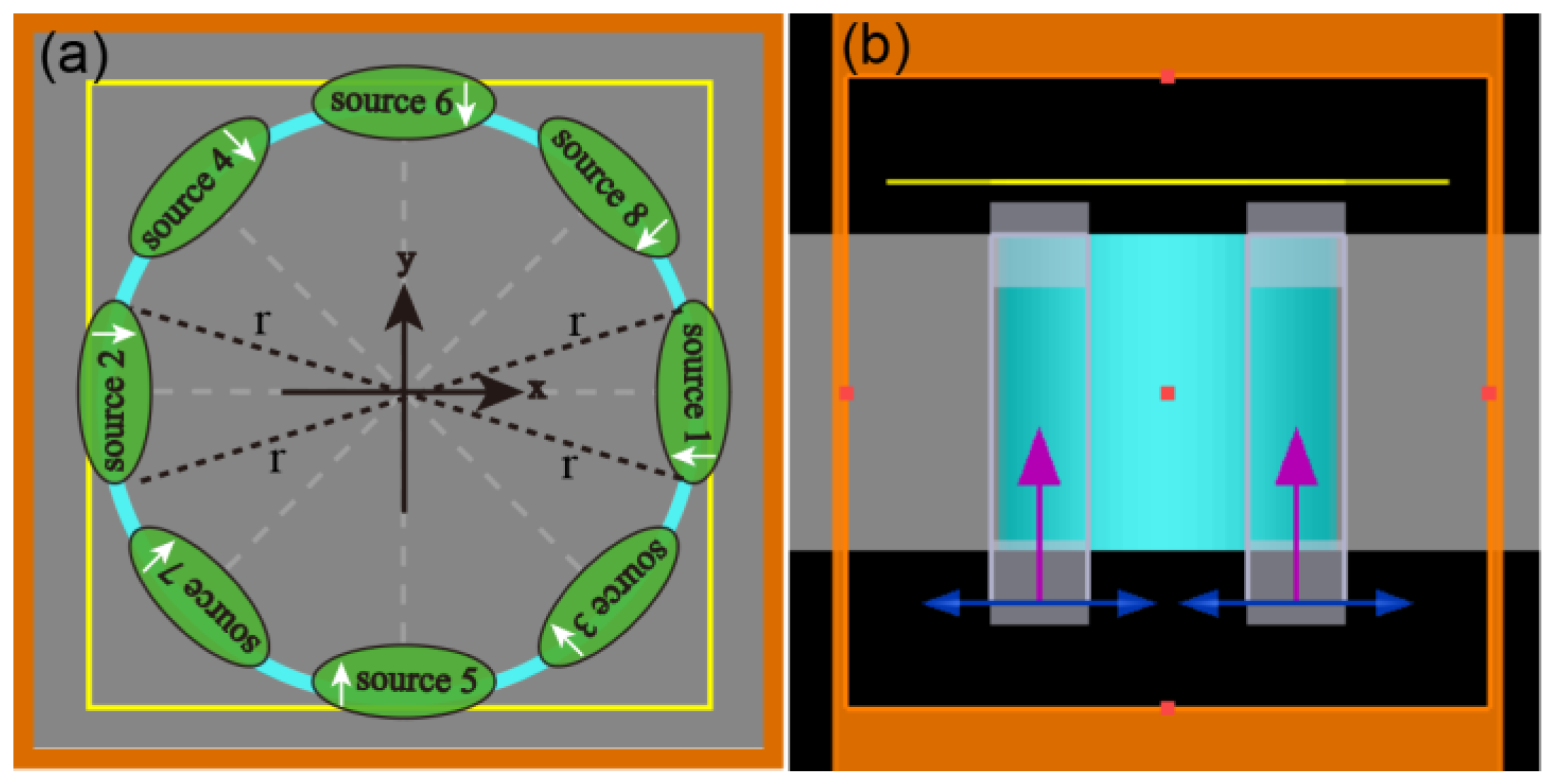
Figure 1 illustrates a schematic diagram of an annular slit that is excited by multiple sets of linearly polarized beams with the polarization direction oriented toward the center. The annular slit, with an inner radius of 2 µm and a width of 100 nm, is fabricated in a 120 nm Ag film. “Total-field scattered-fields” with a wavelength of 532 nm were used as the incident beams, which were used to illuminate the structure from the back side normally. As per the vector field generation method [
39], any number of multifocal arrays can be created by designing the phase loading on the SLMs, and the position, phase, polarization, and other parameters of the multifocal arrays can be independently controlled. The Frequency-domain field and power monitors were placed 20 nm above the silver surface. The mesh tape used in the simulation was auto non-uniform, the mesh size was 0.1 um, the symmetric boundary conditions were used in the X and Y directions, and a perfectly matched layer (PML) boundary condition was used in the Z direction. In an experimental implementation, a vector light field generator with the assistance of two liquid crystal spatial light modulators (LC-SLMs) can be used to generate multiple beams and control their phase difference [
39,
40].
3.1. Capture Performance of the Annular Slit Excited by a Set of Symmetric Linearly Polarized Beams
Figure 2 and
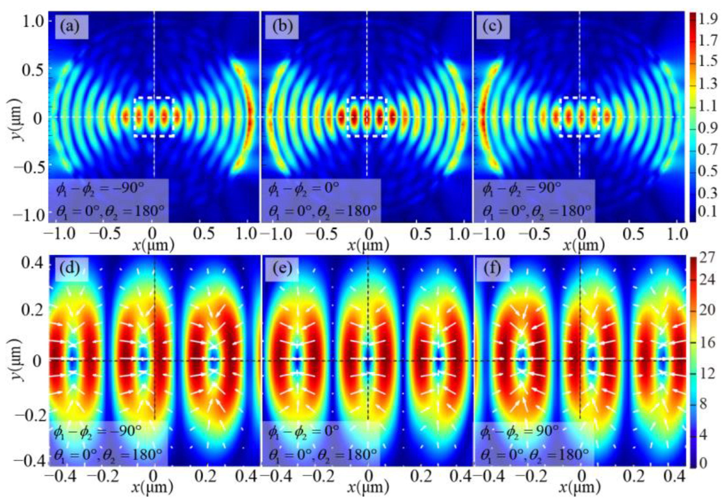
Figure 3 present the distribution of the electric field and optical force when two symmetric linear polarized beams are utilized as the excitation source. Figures in the first row exhibit the distributions of the SPP electric field, while the figures in the second row depict the distributions of optical force corresponding to the white dotted box area in the first row. The color change in the figure symbolizes the intensity, and the white arrow denotes the direction.
ϕ1 and
ϕ2 are phase of source 1 and source 2 in
Figure 1a, respectively,
θ1 and
θ2 are their corresponding azimuth angles.
Figure 2 demonstrates the effect of changing the phase difference between two incident beams. It can be seen that the SPP focus can be moved by changing the phase difference of two incident beams. When
ϕ1 −
ϕ2 = 0°, as shown in
Figure 2b,e, the electric field is symmetrically distributed along the
y-axis, and the SPP focus appears at the center. The direction of the optical force is pointing toward the maximum intensity of the SPP focus, so particles can be captured to the center. On the other hand, when
ϕ1 −
ϕ2 = −90°, as shown in
Figure 2a,d, the SPP focus shifts to the left, but the direction of the electric field vector and optical force remains unchanged. Conversely, when
ϕ1 −
ϕ2 = 90°, the SPP focus shifts to the right, as shown in
Figure 2c,f. It can be inferred that these SPP foci are capable of not only capturing particles but also moving them by adjusting the phase difference between the two excitation beams.
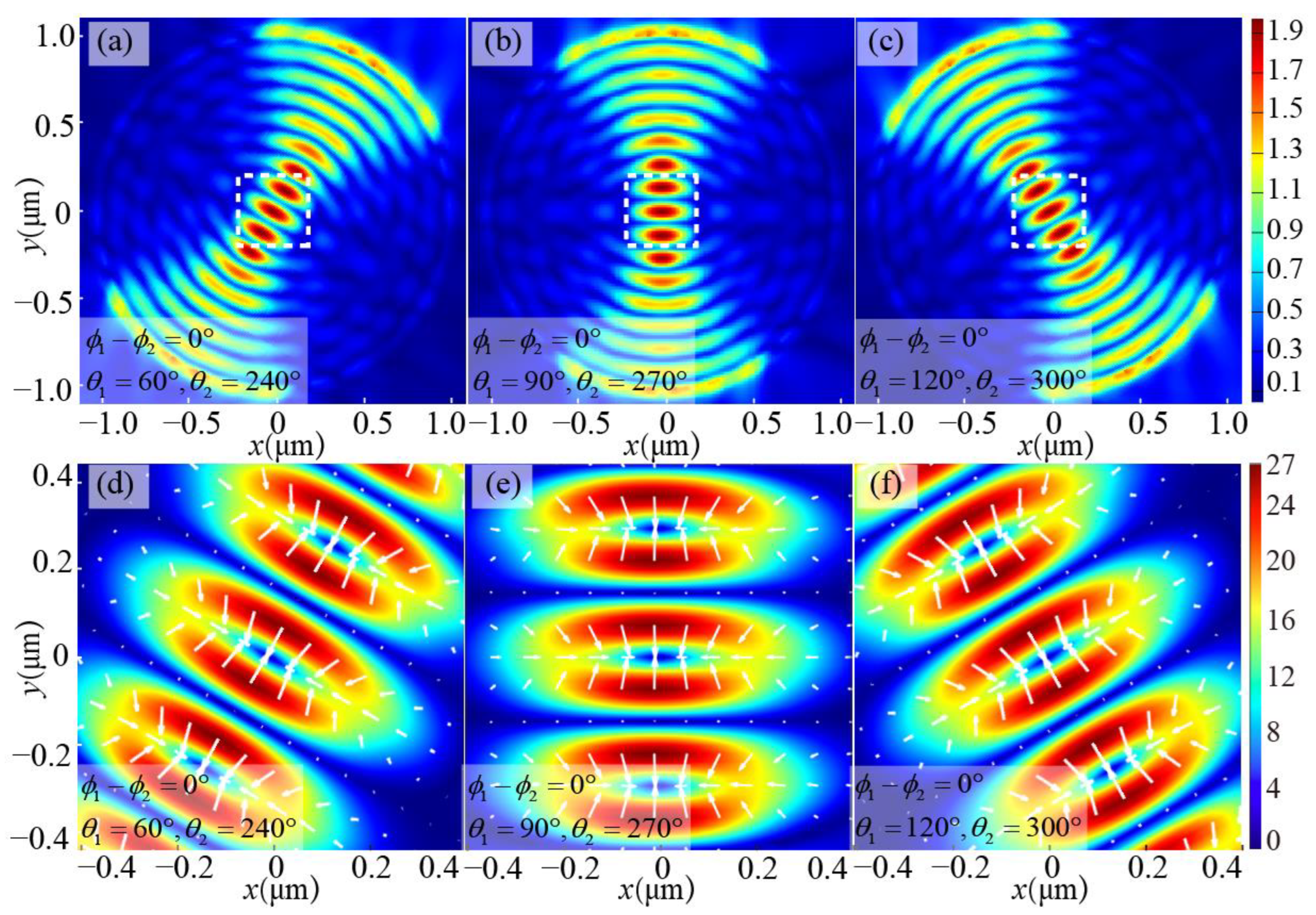
Additionally, as demonstrated in
Figure 3, the SPP focus can be rotated by rotating the azimuth angles of incident beams when the incident beams are rotated to various angles, resulting in the corresponding rotation of the electric field and optical force distribution. For instance, as the incident beams are at 60° and 240°, the electric field and optical force distributions are shown in
Figure 3a,d; then when the incident beams rotate 30° counterclockwise, it corresponds to a vertical position,
Figure 3b,e shows the distribution of the generated electric field and optical force; and when the excitation beams continue to rotate at 30° counterclockwise, it corresponds to
Figure 3c,f. This shows that the captured target can be rotated with the rotation of the incident beams when the annular slit is excited by the double beams. Moreover, the phase difference between the two incident beams can be adjusted simultaneously when they rotate in different directions so that the captured particles can not only rotate 360° but also travel along the diameter of any angle. Finally, the rotation of the double beams can be clockwise or counterclockwise, and the rotation of the captured particles will follow suit.
The above findings demonstrate that by utilizing a single set of beams as the excitation source for the annular slit, the generated SPP field is capable of capturing spherical metal particles. Furthermore, these SPP fields can not only move the particles by adjusting the phase difference between the two incident beams but also rotate them by rotating the incident beams. As a result, the captured particles can be moved in any desired direction inside the annular slit.
3.2. Focus and Capture Performance of the Annular Slit Excited by the Radially Polarized Beam
The annular slit can also be excited by multiple sets of symmetrical beams. When multiple sets of linearly polarized beams are used to excite the annular slit, the SPP field is similar to that produced by the four-arc slit in the previous study [
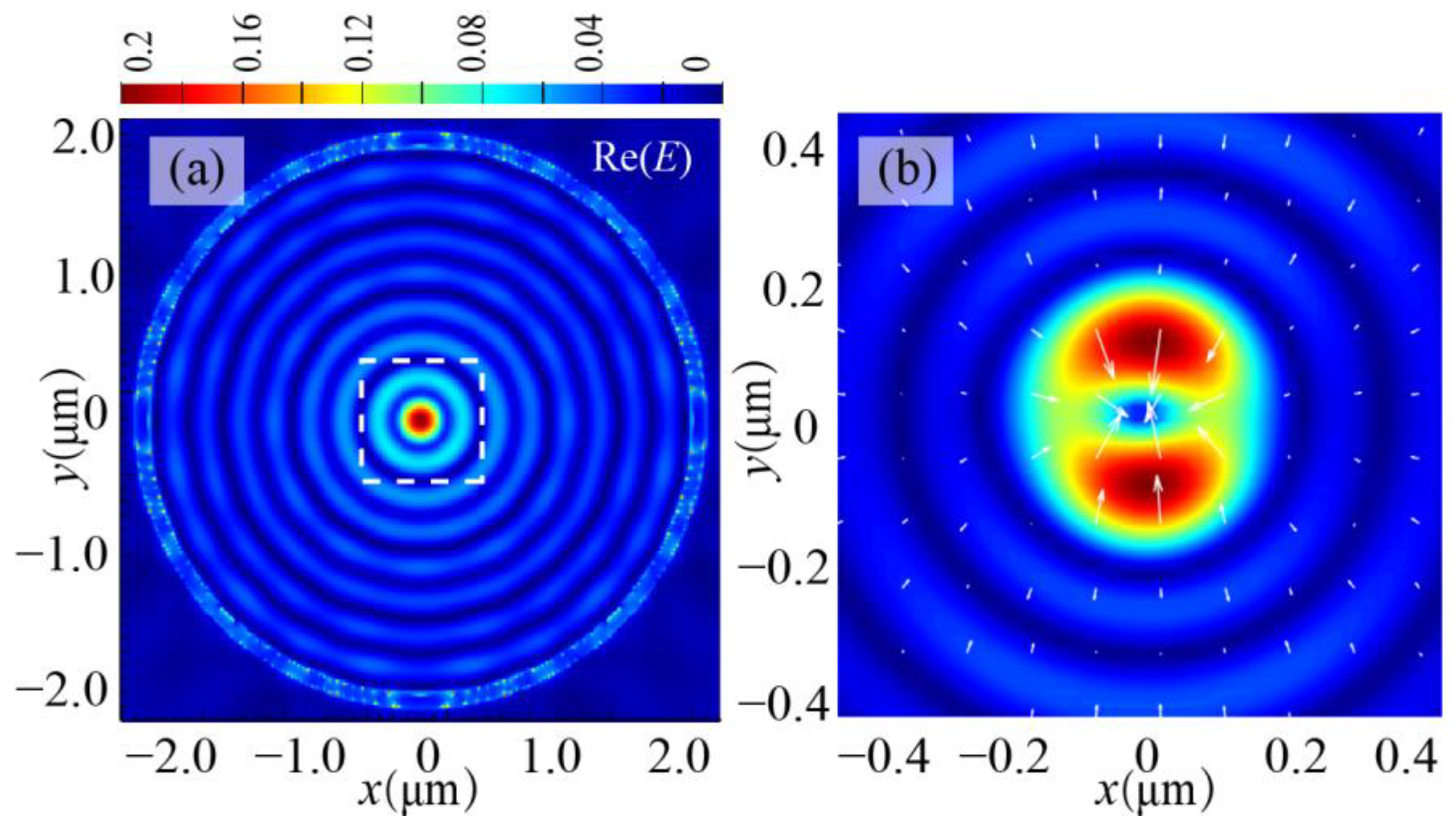
29], namely a single circular SPP focus is generated. Its optical capture performance will not be analyzed repeatedly. It should be noted that when the number of excitation beams is higher, the greater the intensity of SPP focus due to the convergence effect, the more stable the capture is. Let us look at an extreme case. When the number of excitation beams is very large, the excitation source can approximate the radially polarized beam. The distribution of the electric field and optical force in an annular slit is shown in
Figure 4. As shown in
Figure 4a, the SPP is perpendicular to the annular slit and propagates to the center, forming a series of concentric rings and an SPP focus at the center.
Figure 4b shows that the optical force points to the center and increases as it approaches the center, ultimately yielding a zero resultant force at the center.
Subsequently, the examination of the optical force and the trapping potential of particles in the SPP field is conducted. In the vertical direction, due to the exponential decay of SPPs, the particle is drawn toward the silver surface by the strong vertical gradient force. On the other hand, in the horizontal direction, as the annular slit is at 360° rotationally symmetric, the analysis is limited to the optical force along the radial direction.
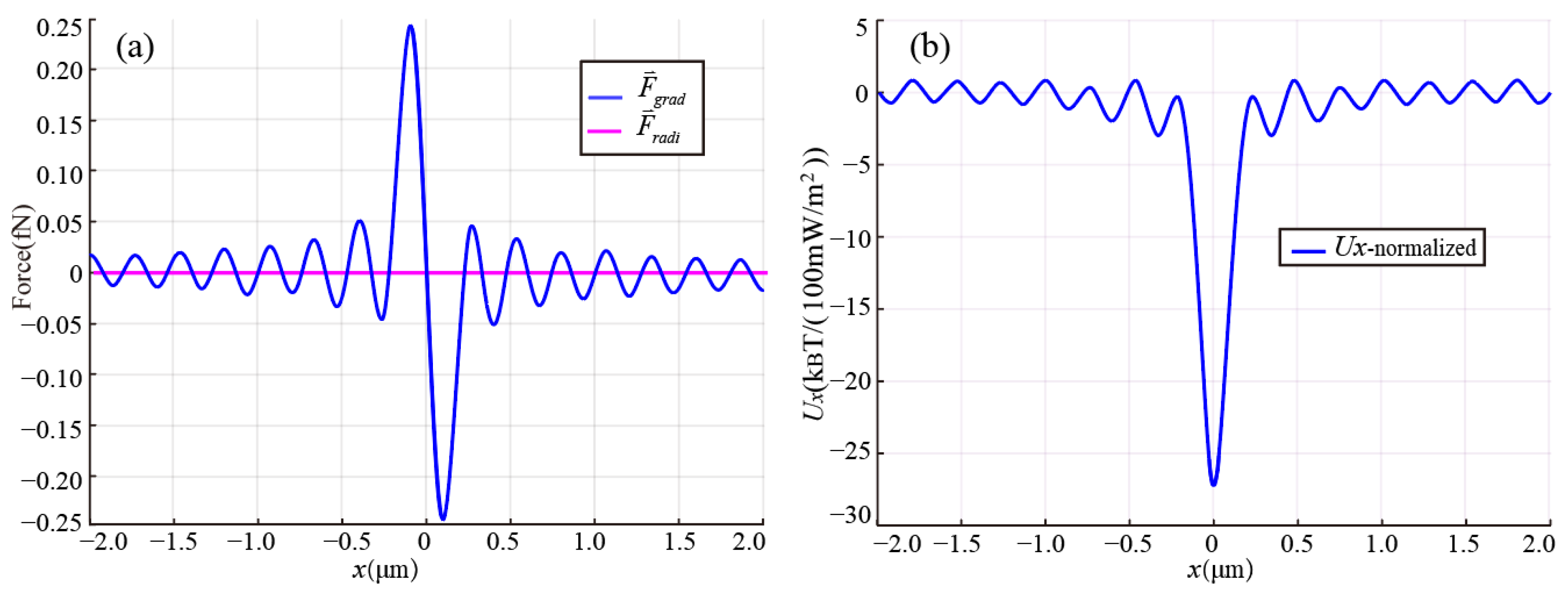
Figure 5a illustrates the radial force distribution of a gold particle with a radius of 35 nm in the SPP field, under an average power density of the excitation beam of 0.083 mW/m
2. Firstly, it can be observed that the radial scattering force is significantly smaller compared to the gradient force, implying that the gradient force plays a predominant role in optical capture. Secondly, there are multiple points in the gradient force curve where the force magnitude is zero, which indicates that particles will be trapped in the high-intensity SPP rings and SPP focus.
To assess the stability of particle capture, we computed the horizontal trapping potential, normalizing it to an average incident light power density of 100 mW/m
2, using Equation (5). As depicted in
Figure 5b, potential wells are regularly distributed from the center to the periphery. In theory, these potential wells would attract nearby particles and confine them to the center. However, due to the influence of Brownian motion, particles will escape when the potential well is shallow. Hence, as an additional sufficient capture condition, the depth of the potential well at the SPP focus is required to reach 10 k
BT to ensure a stable capture [
2,
37].
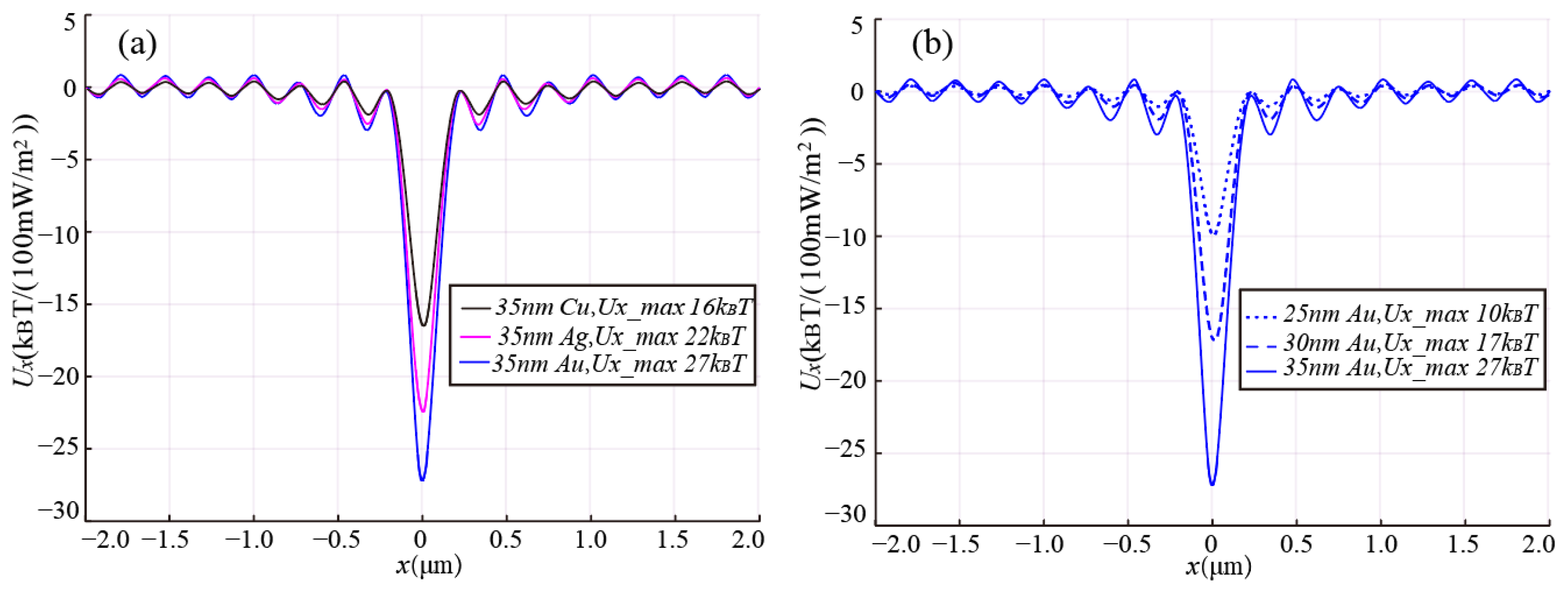
To demonstrate the stability of particle capture by the annular slit when excited by a radially polarized beam, we evaluated the optical trapping potential of particles of various materials and sizes, as illustrated in
Figure 6.
Firstly, it is apparent from
Figure 6a that the trapping potential energy for particles with the same radius of 35 nm, but composed of different materials, varies. The trapping potential for the gold ball is the greatest, followed by the silver ball (ε
Ag = −10.1972 + 0.826151i), while that of the copper ball (ε
Cu = −5.58968 + 5.52022i) demonstrates the lowest. This disparity is mainly due to their distinct dielectric constants. Nonetheless, the trapping potential of all these three balls surpasses 10 k
BT, which ensures stable capture [
2,
37].
Secondly,
Figure 6b shows that, for the same material, a reduction in particle size will lead to a reduction in capture potential energy. This implies that when capturing particles with a smaller radius, they may escape due to insufficient capture potential energy, and their trapping difficulty will increase. A particle with a capture potential energy of 10 k
BT is considered the smallest particle that can be stably captured. Therefore, it can be seen from
Figure 6a that the smallest gold sphere that can be stably captured is about 25 nm. In addition, the calculation results show that the smallest radii for silver and copper spheres are 27 nm and 30 nm, respectively.
In summary, when the annular slit is excited by a radially polarized beam, a single strong focus is generated that can be used to capture small particles. The trapping potential energy varies for particles of different materials, and it becomes increasingly challenging to capture particles with a smaller radius for particles of the same material.
3.3. Comparison of Optical Capture Performance between a Set of Symmetric Linearly Polarized Beams Excitation and Radially Polarized Beam Excitation
The SPP fields generated by exciting the annular slit with linearly polarized beams and the radially polarized beam are significantly different, leading to changes in optical trapping performance. First, the SPP field excited by a set of symmetric linearly polarized beams has multiple SPP foci, which makes it possible to achieve the parallel capture of multiple optical traps. On the contrary, the radially polarized beam excitation produces a single SPP focus, so there is only one optical trap. Secondly, the SPP focus excited by a single set of linearly polarized beams is elliptical, while the SPP focus excited by the radially polarized beam is circular, which shows that it is evident that the circular focus can achieve a more accurate location of the particle. Finally, the SPP optical trap excited by linearly polarized beams can achieve the rotation and movement of particles by adjusting the position and phase difference of the incident beams. Conversely, the use of a radially polarized beam results in a more stable localization of the particle within the SPP optical trap. In short, the distribution characteristics of the SPP fields generated by the excitation of linearly polarized beams and radially polarized beams are different, thus achieving different particle capture capabilities.
4. Conclusions
This study sheds light on the particle capture performance of an annular slit excited by vector light fields. The SPP fields and their particle capture performance produced by linear polarized beams and radially polarized beams are verified and compared. The results indicate that, in a set of symmetrically linearly polarized beam excitations, the rotation and movement of the particles can be enabled by rotating the incident beams and changing their phase difference. On the other hand, in the radially polarized light excitation, the high-intensity SPP focus can achieve the stable capture of particles with varying radii and materials. Although both excitation modes confirm the excellent particle trapping performance of annular slits, it is undeniable that they also have their own limitations. For the dual-beams excitation, the radial motion distance of the particles is limited due to the convergence of the annular slit limiting the SPP focus range. On the other hand, stable particle capture can be achieved with radially polarized light excitation, albeit at the cost of inhibiting particle motion. Indeed, the different capture performance depends on the SPP field distribution which in turn depends on different incident beams; thus, different vector light fields can be selected as excitation sources as per the needs of practical applications to achieve different particle trapping performances.


