Article

Study on the Expansion Kinetics of Plasma and Absorption Wave Induced by Millisecond-Nanosecond Combined Pulse Lasers in Fused Quartz

1
Jilin Key Laboratory of Solid-State Laser Technology and Application, School of Physics, Changchun University of Science and Technology, Changchun 130022, China
2
Chongqing Research Institute, Changchun University of Science and Technology, Chongqing 401135, China
*
Author to whom correspondence should be addressed.
Photonics 2023, 10(4), 411; https://doi.org/10.3390/photonics10040411
Submission received: 6 November 2022 / Revised: 31 December 2022 / Accepted: 19 January 2023 / Published: 6 April 2023

Abstract

:
The transient temperature field, the velocity and pressure of plasma, and the absorption wave of fused quartz induced by millisecond-nanosecond combined pulse lasers are simulated. The theoretical model of plasma and absorption wave produced by fused quartz irradiated by a millisecond-nanosecond pulsed laser is established, in which pulse delay and laser energy are essential variables. The results show that the damaged effect of the millisecond-nanosecond combined pulse laser is different under the damaged effect of different pulse delay conditions. When the energy densities of millisecond-nanosecond combined pulse lasers are 800 J/cm2 and 20 J/cm2, respectively, the range of pulse delay is 0 ms <   Δ t   ≤ 3 ms, and the energy coupling efficiency is the highest when Δ t = 1 ms. The addition of a nanosecond pulsed laser causes more obvious thermal damage and optical breakdown to fused quartz. The high pressure is concentrated at the plasma expansion interface or the shock wave front. The results can optimize the simulation parameters and be applied to laser plasma processing technology.

1. Introduction

With the development of high-power and high-energy laser systems, the damage that an intense laser induces to optical components has hindered the sustainable development of large laser systems. Fused quartz is widely used as a visual element in the solid-state laser system. Laser-supported plasma and the combustion wave produced by fused quartz irradiated by high-power lasers are some of the main reasons for damage. The damage mechanism of high-energy and high-power lasers to fused quartz is different. For a high-energy laser of millisecond magnitude, the action time is relatively long. The heat can be transferred from the surface to the interior of fused quartz. Fused quartz has a considerable depth of laser absorption, resulting in a temperature gradient in the material, and the damage is mainly caused by thermal melting damage. For a high-power laser of nanosecond magnitude, the pulse width is minimal and the power density is very high, so the thermal damage usually occurs only on the material’s surface. Force damage is caused by nonlinear effects caused by laser electric fields, such as nonlinear absorption, nonlinear refractive index, and the self-focusing effect. The damage caused by force on the material is mainly explosion. A nanosecond pulse laser mainly produces plasma via a non-heating mode, while a millisecond pulse laser mainly produces plasma by heat transfer. Some things could be improved in the application of both. Although the peak power of a nanosecond pulsed laser is large and it is easy for it to generate plasma, the plasma produced is short due to its insufficient energy and quick action time. The plasma produced by millisecond pulsed lasers has a small intensity, but the plasma produced by its high energy lasts longer. Through the suitable combination of milliseconds and nanoseconds, the problems of short duration and low power of plasma generated by a single pulse laser can be solved. Compared with a single pulse laser, the damage effect of fused quartz by combined pulse lasers is more prominent, which can effectively improve the efficiency of laser coupling. Among these types of lasers, the combination mode of a millisecond-nanosecond pulse laser can make full use of the thermal effect of a millisecond pulse laser and the mechanical impact of a nanosecond pulse laser, effectively improving the efficiency of laser action and improving the interaction quality between the laser and material. However, there are few studies on the interaction between combined pulse lasers and matter, so the research on the effect, law, and mechanism of millisecond-nanosecond combined pulse lasers needs further improvement [1,2,3,4,5,6].
Over the years, researchers at home and abroad have carried out extensive theoretical, simulation, and experimental research on the interaction process between lasers and fused quartz. They mainly discussed the effects of different laser parameters, different film properties of materials, and different production processes on the damage of fused quartz and made significant progress. The current research shows many studies on the interaction between a single pulse laser and fused quartz optical elements, most of which are short-pulse lasers. Still, there are relatively few reports about combined pulse lasers. In addition, the damage mechanism of plasma and absorbing waves induced by a millisecond-nanosecond pulsed laser in fused quartz is still unclear, and further research is still needed. Laser-supported plasma has been used in the field of laser shock strengthening technology. That is, the thermodynamic effect of the laser-induced plasma and shock wave on the target is used to achieve the purpose of target performance improvement, target composition analysis, and target movements, such as laser shock strengthening, laser plasma spectral analysis, and laser propulsion. As the processing technology of the laser-supported plasma and shock wave is well-known by more and more people, laser propulsion has become a hot spot of current research [7,8,9]. Laser-supported absorption waves have been used in the field of laser propulsion. They can act on the flying body, promote the movement of the flying body, and realize laser propulsion, which can obtain a higher specific impulse than traditional chemical propulsion. Laser propulsion can be widely used in aerospace and weapon technology. The energy conversion of laser propulsion is mainly realized by a laser-supported absorption wave, so the study of laser-supported absorption waves is of great significance to laser propulsion technology. In recent years, Y A May and others established a self-consistent finite element model of laser-induced plasma plume, quantified the transient dynamics of a steam plume under different laser incident intensities, and analyzed the gas flow patterns, such as the mushroom-shaped structure of a steam plume [10]. M. F. Gilljohann and others used femtosecond lasers to accelerate the generation of a plasma wake field by an electron beam, capturing the dynamics of plasma induced by the beam [11]. HALEY KERRIGAN et al. studied the laser–plasma interaction during the ablation of materials by femtosecond filaments superimposed by low-intensity nanosecond pulses, indicating that the interaction between secondary pulses and pre-existing plasma plays a crucial role in enhancing material removal [12]. Li, J.Y., Yang, Z.F., Cao, S.Q., Lv, X.M. studied the effects of different combinations of laser parameters on plasma and absorbed waves [13,14,15,16,17,18].
Although some researchers have researched combined pulse lasers, there are few studies on the combination of millisecond-nanosecond long and short pulses. Therefore, based on the theory of gas dynamics, this paper establishes a simulation model of the effect of pulse delay and nanosecond laser energy density on the temperature change of fused quartz and the evolution of plasma and absorbing wave velocities. The results can optimize the simulation parameters and study the mechanism of a laser plasma absorbing wave. These results can be used in laser plasma processing technology to improve the performance of targets, plasma spectral analysis, and laser propulsion.

2. Theory

In the process of interaction between a laser and fused quartz, the state of the fused quartz changes from a solid state to a molten state and then to gaseous state. When the laser interacts with the ejected target steam, the target vapor ionizes and breaks down, producing high-temperature and high-pressure plasma and forming a plasma absorption zone. The plasma will continue to absorb the energy of the follow-up laser in a short time, and the temperature will rise rapidly. When the temperature of the plasma reaches a critical value, it will expand outward and compress the surrounding air to form the shock wave. The shock wave has a recoil pressure on the surrounding gas, which ionizes the gas to produce free electrons. The free electrons on the side close to the laser source absorb laser energy through inverse Bremsstrahlung to form a new plasma absorption layer. This layer shields the absorption of laser energy by the plasma layer behind, and it forms a laser-supported absorption wave in the incident direction of the reverse laser beam. Among them, laser-supported absorption waves include combustion waves propagating at subsonic speeds and detonation waves bearing at supersonic speeds [19,20,21,22].
Figure 1 shows the simulation diagram of plasma and absorption waves produced by laser-induced fused quartz. The laser beam is parallel and incident vertically on the fused quartz substrate. The solution region is rectangular with an axial length R = 50 mm and radial length Z = 50 mm.
In the process of laser-supported absorption wave propagation, it is assumed that the plasma is an incompressible fluid, the target vapor is in local thermodynamic equilibrium, its turbulence effect is ignored, and the air flow is in the form of laminar flow. The dynamic characteristics of plasma are related to temperature, velocity, and pressure, mainly considering the effects of the inverse Bremsstrahlung process, thermal radiation process, heat conduction process, and thermal convection process on the whole transport process. The hydrodynamic model is as follows [23,24,25,26,27]:
Mass conservation equation
ρ t + ( ρ v ) = 0
Regarding the substrate as an incompressible fluid, the mass conservation equation can be simplified as follows:
( ρ v ) = 0
Let the volume surrounded by any surface area S be V, and the mass of the fluid flowing out of V per unit of time satisfies
d dt V ρ vdV = V ρ t dV
v = {   v m   t < Δ t   v m + v n   t Δ t
In the formula, ρ is the density, v is the airflow velocity produced by the combined pulsed lasers, and v m and v n are the airflow velocities produced by millisecond pulsed laser and nanosecond pulsed laser, respectively.
Navier–Stokes equation
ρ ( v · ) v = ( p + 2 3 η · v ) + · ( η ( v + v ˜ ) ) + ( ρ 0 ρ ) g
Energy conservation equation
ρ c p T t + ρ c p v T = ( λ T ) + m = 1 N m c χ m ( U m U eq , m ) + μ I τ exp ( r 2 r 0 2 ) exp ( 0 z μ dz )
In the formula, ν is the gas velocity, T is the temperature, p is the deviation of the actual pressure, g is the gravitational acceleration, C p , η , and λ are the specific heat capacity, viscosity coefficient, and thermal conductivity, respectively, and μ is the inverse Bremsstrahlung absorption coefficient of the plasma to the laser energy.
Solve the transient heat conduction equation in the air and substrate region:
ρ i c p , i T t + ρ i c p , i ( v T ) = ( k i T )
In the formula, c p , i , k i   , and ρ i are the specific heat, thermal conductivity, and density of the fluid, respectively; v is the phase transition velocity of the fluid, T is the temperature of the fluid, and i = 1 , 2 , 3 7 represents the dielectric materials of each layer in the model.
The laser heat flux lost by evaporation on the substrate surface is as follows:
P = P n + P m m ˙ L v
Millisecond pulse laser power:
P m = J m τ m f ( r ) g ( t )
Nanosecond pulse laser power:
P n = J n τ n f ( r ) g ( t )
The Gaussian spatial distribution f ( r ) of the pulsed laser is
f ( r ) = exp ( 2 r 2 R 0 2 )
The time distribution g m ( t ) of the millisecond pulse laser is
g m ( t ) = {   1 ,   Δ t m t Δ t m + τ m   0 ,   t Δ t m   or   t Δ t m + τ m
The time distribution g n ( t ) of nanosecond pulse laser is
g n ( t ) = {   1 ,   Δ t n t Δ t n + τ n 0 ,   t Δ t n   or   t Δ t n + τ n
Among them, the initial time of fused quartz by the millisecond-nanosecond pulse laser is t 0 , the initial time of the fused quartz by the millisecond pulse laser is   t m , and the initial time of the fused quartz by the nanosecond pulse laser is t n . The delay of the millisecond pulse laser t m relative to the initial time t 0 is Δ t m , and the delay of the nanosecond pulse laser   t n relative to the initial time t 0 is Δ t n .The delay of the nanosecond pulse laser relative to the millisecond pulse laser is counted as Δ t = Δ   t n Δ t m , where τ m is the millisecond pulse width and τ n is the nanosecond pulse width.
Compared with the evaporation loss, the radiation loss is negligible, and the convection loss is taken into account in the modeling, because the air flow is solved near the material and gas interface. In addition, it is assumed that there is thermal continuity on the liquid–gas interface:
T gas = T substrate
The ablation rate is obtained by recording the mass, momentum, and energy conservation of the entire Knudsen layer, which is usually expressed by the Hertz–Langmuir relationship:
m ˙ H L = ( 1 β R ) M 2 π RT P sat ( T )
In the formula, β R is the inverse diffusion coefficient (the fraction of vaporized particles re-condensed when interacting with the surrounding particles), M is the molar mass of evaporated matter, and P sat is the saturated vapor pressure.
The saturated vapor pressure P sat is calculated according to the Claμsiμs–Clapeyron law:
P sat ( T ) = P atm exp [ ML v RT V ( 1 T V T ) ]
where P atm is the atmospheric pressure and T V is the boiling point at atmospheric pressure.
The recoil pressure P rec is
P rec = 1 2 ( 1 + β R ) P sat ( T ) k
The laser-supported absorption wave can be regarded as a mathematical discontinuity with no width, on which the laser energy is completely absorbed. The law of conservation of mass, momentum, and energy is applied to the wavefront without considering heat conduction and viscosity. The spreading velocity of the absorbing wavefront can be calculated.
Mass conservation equation:
ρ 0 ( D u 0 ) = ρ ( D u )
Momentum conservation equation:
ρ 0 ( D u 0 ) ( u u 0 ) = P P 0
Energy conservation equation:
A = Δ E k + Δ E
In unit volume and unit area, the kinetic energy, internal energy, and work conducted by the medium with mass ρ 0 ( D u 0 ) in front of the wave array are
Δ E k = 1 2 ρ 0 ( D u 0 ) ( ( D u ) 2 ( D u 0 ) 2 )
Δ E = ρ 0 ( D u 0 ) ( ε ε 0 )
A = p 0 ( D u 0 ) p ( D u )
The pressure of the laser-supported detonation wavefront is
P = ρ 0 D 2 γ + 1
The plasma density behind the detonation wavefront is
ρ = ρ 0 ( 1 + 1 γ )
The temperature of the detonation wavefront is
T = p / R ρ
In the formula, D is the detonation wave velocity, γ is the gas adiabatic index, ρ 0 is the density when the air is undisturbed, and R is the air gas constant.

3. Simulation Results and Analysis

The parameters of the simulation are as follows in Table 1 and Table 2.

3.1. Temperature and Velocity Variations under Different Pulse Delay Conditions

When the energy density of the millisecond pulsed laser is 800 J/cm2 and the energy density of the nanosecond pulsed laser is 20 J/cm2, the simulation results of the temperature of fused quartz center irradiated by combined pulsed lasers with different pulse delays are shown in Figure 2. When the nanosecond pulse laser is used, the temperature at the center of the fused quartz shows a sharp rise. With the change in ∆t, the peak temperature is constantly changing. Due to the high peak power density of the nanosecond pulse laser, the target is vaporized and ionized to form a plasma under the irradiation of the nanosecond pulse laser. The plasma completely absorbs the laser energy and leaves the target. In addition, the temperature evolution induced by the nanosecond pulsed laser lasts only about 30 μs. When 0 ms < ∆t ≤ 1 ms, the nanosecond pulse laser acts in the early stage of millisecond pulse laser irradiation, and the pre-irradiation of the millisecond pulse laser has relatively little effect on the temperature rise of the nanosecond pulse laser irradiated target. When 1 ms < ∆t ≤ 3 ms, the nanosecond pulsed laser acts after the millisecond laser stops irradiation. It can be seen that the effect of the nanosecond pulse laser slows down the temperature, and the temperature drops rapidly to a slightly higher temperature than that before the action after the end of the nanosecond laser action. Due to the low power of the millisecond pulse laser, the fused quartz does not reach the melting point (2123 K) and does not produce plasma, but plays a preheating role, which makes it easy to make plasma under the action of the subsequent nanosecond laser.
Figure 2 shows the relationship between the temperature of the center point and the pulse delay when the energy density of the nanosecond laser is 20 J/cm2. Figure 3 shows the relationship between the peak temperature of fused quartz and the plasma expansion velocity when the nanosecond laser energy density is 20 J/cm2 and 30 J/cm2, and the pulse delay is ∆t = 0.2–3.0 ms. As can be seen from the graph, when 0 ms < ∆t ≤ 1 ms. The peak temperature on the surface of the fused quartz and the peak expansion velocity of plasma increase with the increase in ∆t. This is mainly due to the fact that the larger the ∆t is, the more pronounced the temperature accumulation effect of the millisecond pulse laser is, and the higher the initial temperature of the nanosecond pulse laser is, the higher the surface peak temperature of the fused quartz is, and the higher the peak velocity of plasma is. When the temperature at 1 ms < ∆t ≤ 3 ms, the peak temperature and peak velocity decrease with the increase in pulse ∆t, because the temperature of the fused quartz begins to decrease after the millisecond pulse laser stops irradiation, and the peak temperature and peak velocity decrease with the increase in pulse ∆t. Under the above conditions of laser energy and pulse delay, the energy coupling efficiency of the millisecond pulse laser and nanosecond pulse laser is the highest at ∆t = 1 ms.

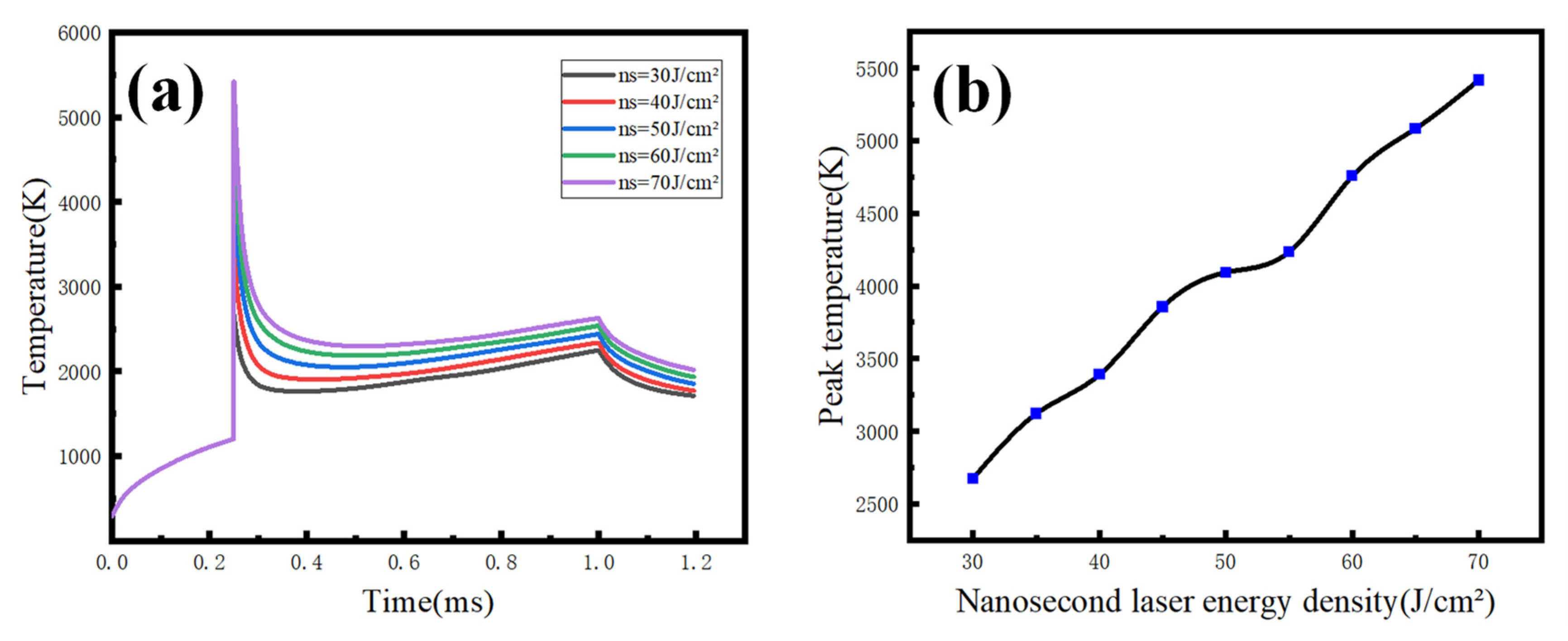
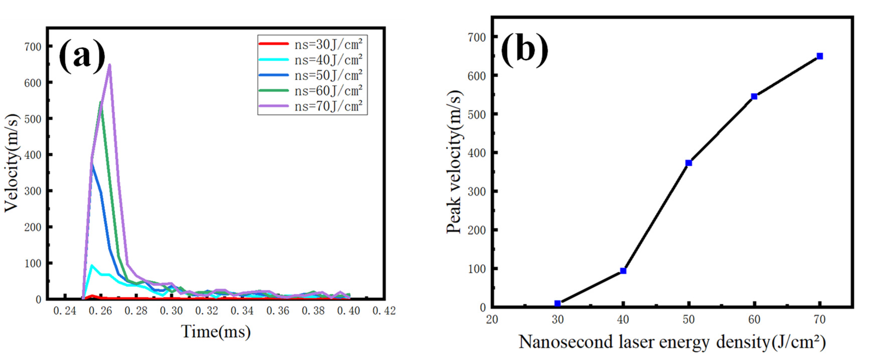
3.2. Temperature and Velocity Changes under Different Nanosecond Pulse Laser Energy Density

Figure 4 shows the temperature change curve of the fused quartz surface center point irradiated by the millisecond-nanosecond combined pulse lasers under the condition of ∆t = 0.25 ms, millisecond pulse energy density of 800 J/cm2, and nanosecond pulse energy density of 30–70 J/cm2. The blue point on the right is the peak temperature when the energy density of the nanosecond pulse laser is 30–70 J/cm2(The energy density interval is 5 J/cm2). The factors that affect the incomplete linearity of the peak temperature variation curve are as follows: (1) Target vapor generally absorbs laser through inverse toughening radiation absorption and photoionization, in which inverse toughening radiation absorption is the main absorption mechanism, and only this main absorption mechanism is considered in the model. (2) The physical parameters of the target, laser absorptivity and reflectivity also vary with temperature. (3) Ignore the situation that the steam temperature is not high and is transparent to the laser. (4) The plasma is regarded as an inviscid compressible fluid and satisfies the law of ideal gas. It can be seen that the temperature change trend is the same under different nanosecond energy densities from the following two pictures. The temperature spike appeared at the time of 0.25 ms, that is, when the nanosecond pulse laser was added. In addition, the peak temperature is positively correlated with the nanosecond pulse laser energy density. The temperature begins to drop sharply after the nanosecond action. However, it is still higher than that before nanosecond action, which is the result of the combined action of the millisecond and nanosecond pulse laser. After that, the fused quartz continues to absorb the millisecond pulse laser energy, and the temperature continues to rise, but the growth is relatively slow. At the time of 1 ms, the millisecond pulse laser action ends and the temperature begins to drop. In the process of temperature change, the pre-irradiation of the millisecond pulse laser increases the initial temperature of the fused quartz. Then, the addition of the nanosecond pulsed laser causes more obvious thermal damage to the fused quartz under the condition of a higher absorption rate of fused quartz.
Figure 5 shows the variation curves of plasma expansion velocity under different nanosecond pulse laser energy densities. The blue point on the right is the peak velocity of plasma expansion when the energy density of the nanosecond pulse laser is 30–70 J/cm2 (The energy density interval is 10 J/cm2).It can be seen from the two diagrams that the plasma expansion velocity is 0 m/s in the 0–0.25 ms period, and the reason is that only the millisecond pulse laser is used at this stage, so the temperature never reaches the gasification temperature of fused quartz, and there is no plasma. At the time of 0.25 ms, due to the addition of the nanosecond pulse laser, the temperature rises obviously, and it is accompanied by the generation of plasma. The peak expansion velocity increases with the increase in nanosecond energy density. This is because the higher the energy of the nanosecond pulse laser, the higher the temperature produced by the pre-irradiation of the millisecond pulse laser, so that when the nanosecond pulse laser irradiates the plasma, the expansion velocity of the plasma increases obviously. After the nanosecond pulse laser ends its action, the plasma expansion velocity decreases suddenly, and finally tends to be flat and close to 1 m/s. This shows that the laser energy cannot maintain the conversion of the laser plasma absorption region into the laser-supported absorbing wave.
Figure 6 shows the velocity and pressure fields of plasma and absorbing waves, which offer a mushroom cloud shape similar to Rayleigh–Taylor instability. The black line with arrowhead represents the velocity streamline. The simulation shows that this structure is formed in the early evaporation stage. The latest schlieren images generated by Bidare under the condition of LPBF show that the mushroom cloud forms tens of millimeters wide within milliseconds after evaporation, and the mushroom shape is caused by the airflow structure produced by the plasma plume [28,29]. The plasma is ejected upward at a relatively high speed. In the initial still air, the air is compressed and moves more slowly than the plasma, which is due to the viscous shear between the plasma plume and the air. The maximum pressure zone and the leading edge of the plume advance vertically, and the air hinders the movement of the vertical plasma plume, resulting in an enormous pressure on the leading edge of the plume. Therefore, the gas in the shear layer is pushed next to the steam plume to form an annular vortex, forming the head of the steam plume, as shown in (d). The annular vortex is represented by a circular velocity streamline.
Figure 7 shows the variation in plasma expansion velocity at millisecond and nanosecond pulsed laser energy densities of 800 J/cm2 and 50 J/cm2, and ∆t = 0.25 ms. The red line in the figure is a local enlarged view of the blue line, in order to more intuitively observe the change trend of plasma expansion velocity and pressure near the maximum value and obtain the change law more accurately. As can be seen from the following two figures, the plasma begins to produce at the time of nanosecond action, when the expansion velocity of the plasma is 65 m/s, the laser absorption wave is produced at the time of 252 μs, the expansion velocity of the laser absorption wave is 197 m/s, the maximum velocity of the absorption wave is 371 m/s at 255 μs, and the expansion velocity of the laser absorption wave is greater than the speed of sound, which is the laser-supported detonation wave. With the end of the nanosecond pulse laser irradiation, the millisecond pulse laser energy cannot maintain the detonation wave propagation at 257.5 μs. At this time, the laser supports the combustion wave to continue to propagate. Still, the propagation velocity decreases gradually, and the propagation velocity of the laser absorption wave decreases to 0.6 m/s at 1.2 ms. The plasma expansion pressure reaches the peak value of 4.09 × 10⁵ Pa at 255 μs, and the high pressure is concentrated at the plasma expansion interface, which is mainly due to the giant plasma expansion velocity, which makes the velocity gradient at the front of the plasma huge, which leads to the increase in the pressure at the plasma expansion interface. At 259 μs, the pressure is mainly concentrated in the shock wave front, which is primarily because the shock wave begins to appear and the reverse laser beam propagates, and the recoil pressure is primarily concentrated in the laser shock wave.
According to Equation (24), the variation in wavefront pressure with time is calculated as shown in Figure 8a. The simulation results are in good agreement with the theoretical results, which reach the peak at 255 μs, where γ = 1.2 and ρ 0 = 1.29 kg/m3. According to Equations (25) and (26), the relationship between the wavefront temperature and pressure is proportional, and the relationship between the wavefront temperature and time is calculated as shown in Figure 8b. The variation trend of the wavefront temperature is consistent with time, and the peak temperature is about 3.81 × 10⁴ K at 255 μs.

4. Conclusions

In this paper, the plasma and absorption wave produced by fused quartz induced by millisecond-nanosecond combined pulse lasers under different pulse delays and different nanosecond energy densities are simulated. The simulation results show the following: (1) The energy density of the millisecond pulse laser is 800 J/cm2, and that of the nanosecond pulse laser is 20 J/cm2 and 30 J/cm2. The pulse delay time acquisition is ∆t = 0.2–3.0 ms, the highest energy coupling efficiency of the millisecond-nanosecond pulsed laser is at the ∆t = 1 ms moment, and the peak temperature and plasma velocity of fused silica increase first and then decrease with ∆t. (2) When ∆t = 0.25 ms, the energy density of the millisecond pulse is 800 J/cm2 and the energy density of the nanosecond pulse is 30–70 J/cm2. The intervention of the nanosecond pulse laser will cause more obvious thermal damage to and optical breakdown of the fused quartz under the condition of a higher absorption rate of the fused quartz. (3) When ∆t = 0.25 ms, the energy densities of the millisecond and nanosecond pulses are 800 J/cm2 and 50 J/cm2, respectively, and the simulation results are in good agreement with the theoretical results. The peak values of wavefront temperature and pressure are consistent with time. At 259 μs, the shock wave begins to appear and propagate against the laser beam, resulting in recoil pressure, which is mainly concentrated in the shock wave front.

Author Contributions

Conceptualization, J.C.; methodology, C.G.; software, C.G.; validation, H.M.; formal analysis, H.Y.; investigation, Y.L.; resources, Y.W.; data curation, C.G.; writing—original draft preparation, C.G.; writing—review and editing, J.C.; supervision, Z.Z.; project administration, C.G.; funding acquisition, J.C. All authors have read and agreed to the published version of the manuscript.

Funding

This research was funded by [Natural Science Foundation of Jilin Province, China] grant number [20220101032JC] and [Natural Science Foundation of Chongqing, China] grant number [cstc2021jcyj-msxmX0842].

Institutional Review Board Statement

Not applicable.

Informed Consent Statement

Not applicable.

Data Availability Statement

Data are available from C.G.

Acknowledgments

We are grateful for the financial support from Jilin Key Laboratory of Solid-state Laser Technology and Chongqing Research Institute.

Conflicts of Interest

The authors declare no conflict of interest.

References

  1. Nguyen, V.H.; Rehman, Z.U.; Janulewicz, K.A.; Suk, H. Dynamics of laser-induced phase transformation in bulk of monocrystalline sapphire. Results Phys. 2022, 40, 105848. [Google Scholar] [CrossRef]
  2. Ye, T.; Yang, L.; An, B.; Zhang, J.; Ding, M. Numerical simulation of the evolution of shock waves and plasma kernels of multi-point laser-induced plasma in supersonic flow. AIP Adv. 2022, 12, 095024. [Google Scholar] [CrossRef]
  3. Hamam, K.A.; Gamal, Y.E.E.D. Numerical analysis of breakdown dynamics dependence on pulse width in laser-induced damage in fused silica: Role of optical system. Results Phys. 2018, 9, 725–733. [Google Scholar] [CrossRef]
  4. Ly, S.; Shen, N.; Negres, R.A.; Carr, C.W.; Alessi, D.A.; Bude, J.D.; Rigatti, A.; Laurence, T.A. The role of defects in laser-induced modifications of silica coatings and fused silica using picosecond pulses at 1053 nm: I. Damage morphology. Opt. Express 2017, 25, 15161–15178. [Google Scholar] [CrossRef] [PubMed]
  5. Somayaji, M.; Bhuyan, M.K.; Bourquard, F.; Velpula, P.K.; D’Amico, C.; Colombier, J.P.; Stoian, R. Multiscale electronic and thermomechanical dynamics in ultrafast nanoscale laser structuring of bulk fused silica. Sci. Rep. 2020, 10, 15152. [Google Scholar] [CrossRef] [PubMed]
  6. Kumar, A.; Kumar, A.; Mishra, S.P.; Yadav, M.S.; Varma, A. Plasma wave aided heating of collisional nanocluster plasma by nonlinear interaction of two high power laser beams. Opt. Quantum Electron. 2022, 54, 753. [Google Scholar] [CrossRef]
  7. Joanni, E.; Kumar, R.; Fernandes, W.P.; Savu, R.; Matsuda, A. In situ growth of laser-induced graphene micro-patterns on arbitrary substrates. Nanoscale 2022, 14, 8914–8918. [Google Scholar] [CrossRef]
  8. Kumar, R.; Pérez del Pino, A.; Sahoo, S.; Singh, R.K.; Tan, W.K.; Kar, K.K.; Matsuda, A.; Joanni, E. Laser processing of graphene and related materials for energy storage: State of the art and future prospects. Progr. Energy Combust. Sci. 2022, 91, 100981. [Google Scholar] [CrossRef]
  9. Kumar, R.; Singh, R.K.; Singh, D.P.; Joanni, E.; Yadav, R.M.; Moshkalev, S.A. Laser-assisted synthesis, reduction and micro-patterning of graphene: Recent progress and applications. Coord. Chem. Rev. 2017, 342, 34–79. [Google Scholar] [CrossRef]
  10. Mayi, Y.A.; Dal, M.; Peyre, P.; Bellet, M.; Metton, C.; Moriconi, C.; Fabbro, R. Laser-induced plume investigated by finite element modelling and scaling of particle entrainment in laser powder bed fusion. J. Phys. D Appl. Phys. 2020, 53, 075306. [Google Scholar] [CrossRef] [Green Version]
  11. Gilljohann, M.F.; Ding, H.; Döpp, A.; Götzfried, J.; Schindler, S.; Schilling, G.; Corde, S.; Debus, A.; Heinemann, T.; Hidding, B.; et al. Direct Observation of Plasma Waves and Dynamics Induced by Laser-Accelerated Electron Beams. Phys. Rev. X 2019, 9, 011046. [Google Scholar] [CrossRef] [Green Version]
  12. Kerrigan, H.; Masnavi, M.; Bernath, R.; Fairchild, S.R.; Richardson, M. Laser-plasma coupling for enhanced ablation of GaAs with combined femtosecond and nanosecond pulses. Opt. Express 2021, 29, 18481–18494. [Google Scholar] [CrossRef] [PubMed]
  13. Li, J.; Zhang, W.; Zhou, Y.; Yuan, B.; Cai, J.; Jin, G. The acceleration mechanism of shock wave induced by millisecond-nanosecond combined-pulse laser on silicon. Plasma Sci. Technol. 2021, 23, 055507. [Google Scholar] [CrossRef]
  14. Li, J.Y.; Zhang, W.; Guo, L.P.; Zhang, X.Y.; Yuan, B.S.; Guo, M.; Jin, G.Y. Experimental study of different pulse delays on the phenomenon of double shock waves induced by a millisecond-nanosecond combined-pulse laser. Appl. Opt. 2020, 59, 7338–7342. [Google Scholar] [CrossRef]
  15. Li, J.; Zhang, W.; Zhou, Y.; Zhang, X.; Jin, G. Experimental study of the damage morphology induced by the millisecond-nanosecond combined-pulse laser with different pulse delay on silicon. Optik 2021, 226, 165904. [Google Scholar] [CrossRef]
  16. Yang, Z.; Wei, W.; Han, J.; Wu, J.; Li, X.; Jia, S. Experimental study of the behavior of two laser produced plasmas in air. Phys. Plasmas 2015, 22, 073511. [Google Scholar] [CrossRef]
  17. Cao, S.; Su, M.; Ma, P.; Wang, K.; Min, Q.; Sun, D.; Cheng, R.; Ying, Y.; Dong, C. Expansion dynamics and emission characteristics of nanosecond–picosecond collinear double pulse laser-induced Al plasma in air. J. Quant. Spectrosc. Radiat. Transf. 2020, 242, 106773. [Google Scholar] [CrossRef]
  18. Lv, X.M.; Pan, Y.X.; Jia, Z.C.; Li, Z.W.; Ni, X.W. Surface damage induced by a combined millisecond and nanosecond laser. Appl. Opt. 2017, 56, 5060–5067. [Google Scholar] [CrossRef]
  19. Xu, Y.; Yang, L.; Zhou, D.; Liu, B.; Li, Q.; Shi, W.; Jin, Y. Experimental study on the dynamics and parameters of nanosecond laser-induced aluminum plasma. J. Phys. D Appl. Phys. 2022, 55, 325201. [Google Scholar] [CrossRef]
  20. Yuan, B.S.; Wang, D.; Dong, Y.; Zhang, W.; Jin, G.Y. Experimental study of the morphological evolution of the millisecond-nanosecond combined-pulse laser ablation of aluminum alloy. Appl. Opt. 2018, 57, 5743–5748. [Google Scholar] [CrossRef]
  21. Wang, M.; Wang, C.; Tao, X.; Zhou, Y. Numerical Study on Laser Shock Peening of Pure Al Correlating with Laser Shock Wave. Materials 2022, 15, 7051. [Google Scholar] [CrossRef]
  22. Protasov, C.E.; Khmyrov, R.S.; Grigoriev, S.N.; Gusarov, A.V. Selective laser melting of fused silica: Interdependent heat transfer and powder consolidation. Int. J. Heat Mass Transf. 2017, 104, 665–674. [Google Scholar] [CrossRef]
  23. Yang, G.; Sun, W.; Wan, F.; Ban, X.; Liu, Q.; Wang, Z.; Zhang, X.; Ma, M.; Zhang, J.; Zhao, B.; et al. Terahertz radiation enhanced by a laser-irradiating on a double-layer target. Eur. Phys. J. D 2022, 76, 189. [Google Scholar] [CrossRef]
  24. Chambonneau, M.; Lamaignere, L. Multi-wavelength growth of nanosecond laser-induced surface damage on fused silica gratings. Sci. Rep. 2018, 8, 891. [Google Scholar] [CrossRef] [PubMed] [Green Version]
  25. Sun, Q.; Lee, T.; Beresna, M.; Brambilla, G. Control of Laser Induced Cumulative Stress for Efficient Processing of Fused Silica. Sci. Rep. 2020, 10, 3819. [Google Scholar] [CrossRef] [PubMed] [Green Version]
  26. Wang, G.; Su, J. Study of the length and influencing factors of air plasma ignition time. Open Phys. 2022, 20, 740–749. [Google Scholar] [CrossRef]
  27. Ikeda, Y.; Soriano, J.K. Microwave-enhanced laser-induced air plasma at atmospheric pressure. Opt. Express 2022, 30, 33756–33766. [Google Scholar] [CrossRef] [PubMed]
  28. Bidare, P.; Bitharas, I.; Ward, R.M.; Attallah, M.M.; Moore, A.J. Laser powder bed fusion in high-pressure atmospheres. Int. J. Adv. Manuf. Technol. 2018, 99, 543–555. [Google Scholar] [CrossRef] [Green Version]
  29. Bidare, P.; Bitharas, I.; Ward, R.M.; Attallah, M.M.; Moore, A.J. Fluid and particle dynamics in laser powder bed fusion. Acta Mater. 2018, 142, 107–120. [Google Scholar] [CrossRef]
Figure 1. Simulation diagram of plasma and absorbing waves produced by laser-induced fused quartz.
Photonics 10 00411 g001
Figure 2. Variation in fused quartz temperature with time under different pulse delay conditions.
Photonics 10 00411 g002
Figure 3. Variation in peak temperature and plasma peak velocity of fused quartz with pulse delay. (a) The variation in peak temperature pulse delay of fused quartz; (b) the variation in plasma peak velocity with pulse delay.
Photonics 10 00411 g003
Figure 4. Variation in fused quartz surface temperature under different nanosecond laser energy conditions: (a) the relationship of the surface temperature of fused quartz with time; (b) the relationship between peak temperature and nanosecond laser energy density.
Photonics 10 00411 g004
Figure 5. The variation in plasma expansion velocity under different nanosecond laser energy: (a) the relationship of plasma expansion velocity with time; (b) the relationship between plasma peak velocity and nanosecond energy density.
Photonics 10 00411 g005
Figure 6. Velocity and pressure fields of plasma and absorbing waves (velocity field on the left and pressure field on the right): (a) t = 250 μs; (b) t = 255 μs; (c) t = 260 μs; (d) t = 265 μs.
Photonics 10 00411 g006
Figure 7. Variation in plasma expansion velocity and pressure with time: (a) he plasma expansion velocity varies with time; (b) plasma pressure varies with time.
Photonics 10 00411 g007
Figure 8. Variation in wavefront pressure and temperature with time: (a) variation in wavefront pressure with time; (b) variation in wavefront temperature with time.
Photonics 10 00411 g008
Table 1. Material parameters.
Feature Parameter NameSymbolDimensionNumerical Value
Plasma density ρ g · cm 3 3.49/T × 10−6
Plasma thermal conductivity K Wm 1 K 1 −0.002 + 1.5 × 10⁻⁴ × T − 7.9 × 10⁻⁸ × T2 + 4.12 × 10⁻¹¹ × T3 − 7.44 × 10⁻¹⁵ × T4
Plasma heat capacity C J / ( kg · K ) 1047.27 + 9.45 × 10⁻⁴ × T2 − 6.02 × 10⁻⁷ × T3 + 1.29 × 10⁻¹⁰ × T4
Plasma viscosity coefficient η Pa · S −8.38 × 10⁻⁷ + 8.36 × 10⁻⁸ × T − 7.69 × 10⁻¹¹ × T2 + 4.64 × 10⁻¹⁴ × T3 − 1.07 × 10⁻¹⁷ × T4
Specific heat rate γ r 11
γ a 11.4
Relative permittivity ϵ a C2·N−1·M−21
Reflectivity R r 10.3
Melting pointTm K 1533
Boiling pointTv K 3190
Absorptivity of 1064 nm A s 1 / K 354.67 × 10⁻⁴ × sqrt(−1.0 + 1.25 × 10⁻² × T)
A l 1 / K 354.67 × 10⁻⁴ × sqrt(10.7 + 1.45 × 10⁻² × T)
Melting latent heat L m J / kg 3.896 × 10⁵
Evaporative latent heat L v J / kg 2.839 × 10⁷
Note: In the subscript, r represents fused silica, a represents air, s represents solid, l represents liquid, m represents melting state, and n represents boiling state.
Table 2. Laser parameters.
Feature Parameter NameSymbolDimensionNumerical Value
Laser wavelength λ nm 1064
Millisecond pulse laser energy density E m J / cm 2 800
Nanosecond pulse laser energy density E n J / cm 2 20–70
Millisecond pulse laser pulse width τ m ms 1
Nanosecond pulse laser pulse width τ n ns 10
Pulse delay Δ t ms 0.2–3.0
Absorption coefficient α 1 / m 1.2992 × 10⁶
Laser spot diameter d mm 1
Disclaimer/Publisher’s Note: The statements, opinions and data contained in all publications are solely those of the individual author(s) and contributor(s) and not of MDPI and/or the editor(s). MDPI and/or the editor(s) disclaim responsibility for any injury to people or property resulting from any ideas, methods, instructions or products referred to in the content.

