1. Introduction
Photonic crystals (PCs) show notable features in their ability to control the motion of photons. The research of PCs is considered to be the core of the future development of photonic devices. PCs can reduce Ohmic loss for high-frequency devices, and to facilitate the development of THz technology, PC low-loss transmission lines were developed [
1,
2,
3]. In a high-power terahertz (THz) system, the sources and high-sensitive detectors are fragile, and the nonreciprocal devices are in urgent demand to protect the fragile devices from backscattering [
4,
5,
6]. The lack of high-performance nonreciprocal devices restricts the development of applications at more than a THz high-power region.
Research on nonreciprocal devices based on magneto PCs (MPCs), which can enhance the magneto-optic (MO) effect, is rapidly developing. In recent years, based on different kinds of MO materials, some progress has been made in the realization of THz nonreciprocal devices [
7,
8]. In 2013, Shalaby et al. presented the first THz isolation based on the traditional Faraday rotation effect in a permanent magnet, of which performance was limited by the large loss of magnets [
9]. In 2018, Fei Fan et al. presented a THz isolator for linear polarized waves composed of InSb thin film sandwiched in a pair of orthogonal dielectric gratings with isolation of 24 dB and insertion loss of 0.5 dB [
10]. The realization of the circulator is based on the nonreciprocal property of materials. For graphene, the conductivity can be controlled by Fermi energy and magnetic field, which can be used to design a circulator with a width bandwidth. However, the restrictions of the intrinsic physical processes in graphene will result in high insertion losses. Nonreciprocity was also observed in some semiconductors in THz frequency, such as InSb and HgTe. They work as magneto plasmonics whose permeability tensor is also asymmetric under an external magnetic field. However, with the restriction of its relative permeability characteristics, it is difficult to reach a width bandwidth. Ferrites are characterized as having great nonreciprocal performance, together with PCs, which are excellent in controlling wave propagation, making it suitable to construct a high-performance THz circulator. From the pre-existing experiment researchers, the PC circulators that approved low loss and wide bandwidth were based on rods in air background structure PCs and cylindrical ferrites [
11]. However, as the operating frequency progressed up into the THz wave range, the size of PC circulators became proportionally small compared to the frequency. The assembly was complicated, and it is difficult to guarantee high accuracy requirements. Thanks to advances in materials science, high-performance terahertz thick-film MO materials can be fabricated to support the design of THz nonreciprocal devices [
12].
In this work, a novel THz circulator based on an MPC slab was envisaged with Al-Ni-Zn ferrite cylinders and an Al2O3 dielectric slab. The air holds a PC slab structure which is removed from the complex assembly, and only a small PEC restriction region on the top and down the plane at the resonance area, effectively reducing the metal Ohmic loss and simplifying the assembly complexity. Moreover, the size and thickness of the device, when also reduced, made it easier to be integrated. The external characteristics of the circulator were calculated using the finite element method (FEM). All the simulation results of this work were carried out on commercial software HFSS. The results show that at the working frequency range 0.212~0.238 THz, the isolation was less than 20 dB, and the insertion loss was better than 1 dB. The excellent circulator performance demonstrates that the MPC slab is a promising method for generating a circulator at high frequency.
2. Analysis of PC Slab Wave-Guide
Circulators are implemented based on different kinds of wave-guide structures, and each kind of structure has its advantages. The PC slab wave-guide has good performance in THz application with its low loss and easy assembly property. PCs with a wide photonic band gap (PBG) are necessary for the realization of an MPC circulator. The material Al2O3 is commonly used in high-frequency applications, and it is also suitable to be used in THz frequency, such as low material loss.
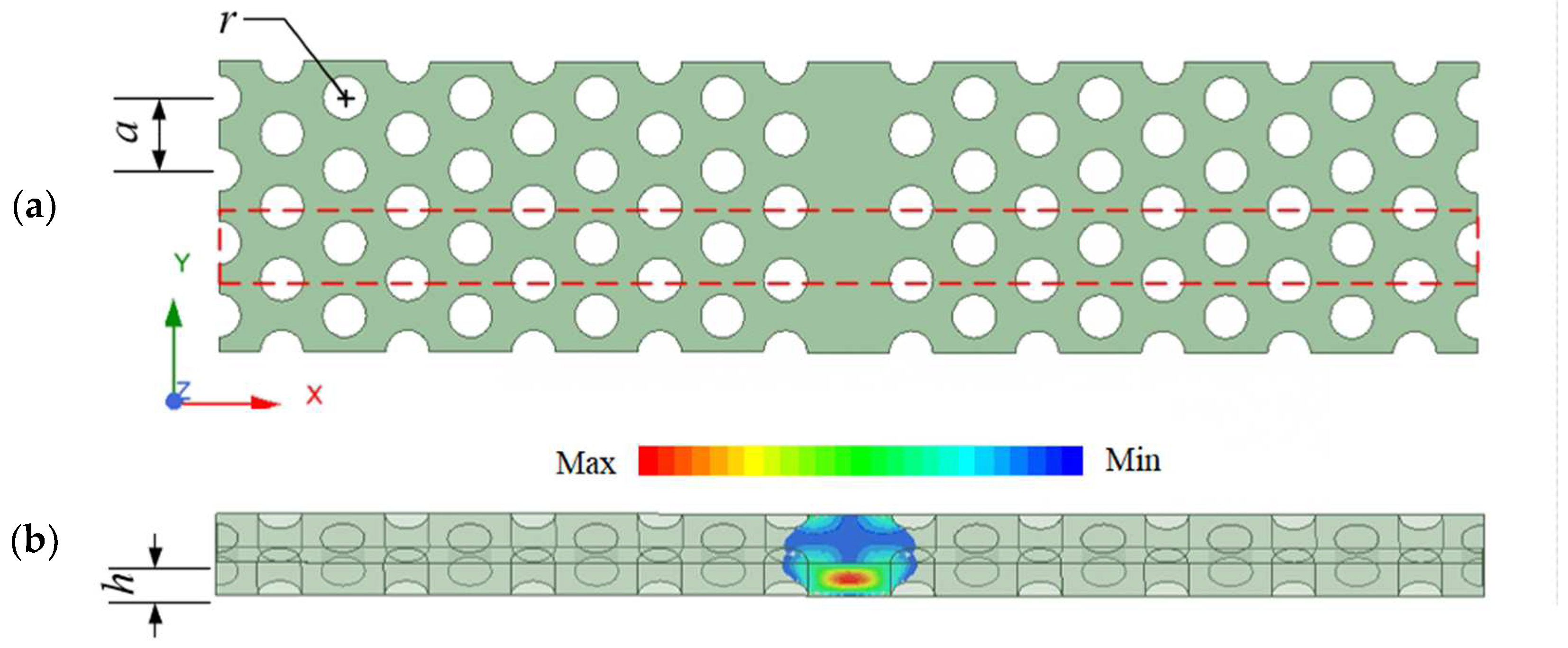
As shown in
Figure 1a, the designed PC slab wave-guide was constructed based on air-hold triangular lattice PCs (TLPCs), with the lattice constant
a = 0.44 mm, the radius of cylindrical air holes
r = 0.13 mm and the slab thickness
h = 0.26 mm. The material Al
2O
3 was also used as a base material to build the PC structure, whose relative permittivity was
εr = 9.2 and relative permeability was
μr = 1. A line defect in the Y-axis was introduced in the center of TLPCs. In the red dashed line region, the super-cell of the PC slab wave-guide and the electric field distribution of waveguide mode is shown in
Figure 1b. The EM wave was confined in the defect position, and at that condition, the PC slab wave-guide could only afford the single-mode operating frequency band.
To evaluate the propagation characteristics of the PC slab wave-guide, the analysis of the projected band structure of the PC guided mode was conducted on the super-cell of the PC slab wave-guide, based on a three-dimensional finite-element method under periodic boundary conditions. The TLPC super-cell was constructed to be three-dimensional with periodic boundary conditions in the propagation direction. The EM waves are confined in the PC slab wave-guide by the geometry and the broken periodicity of PCs.
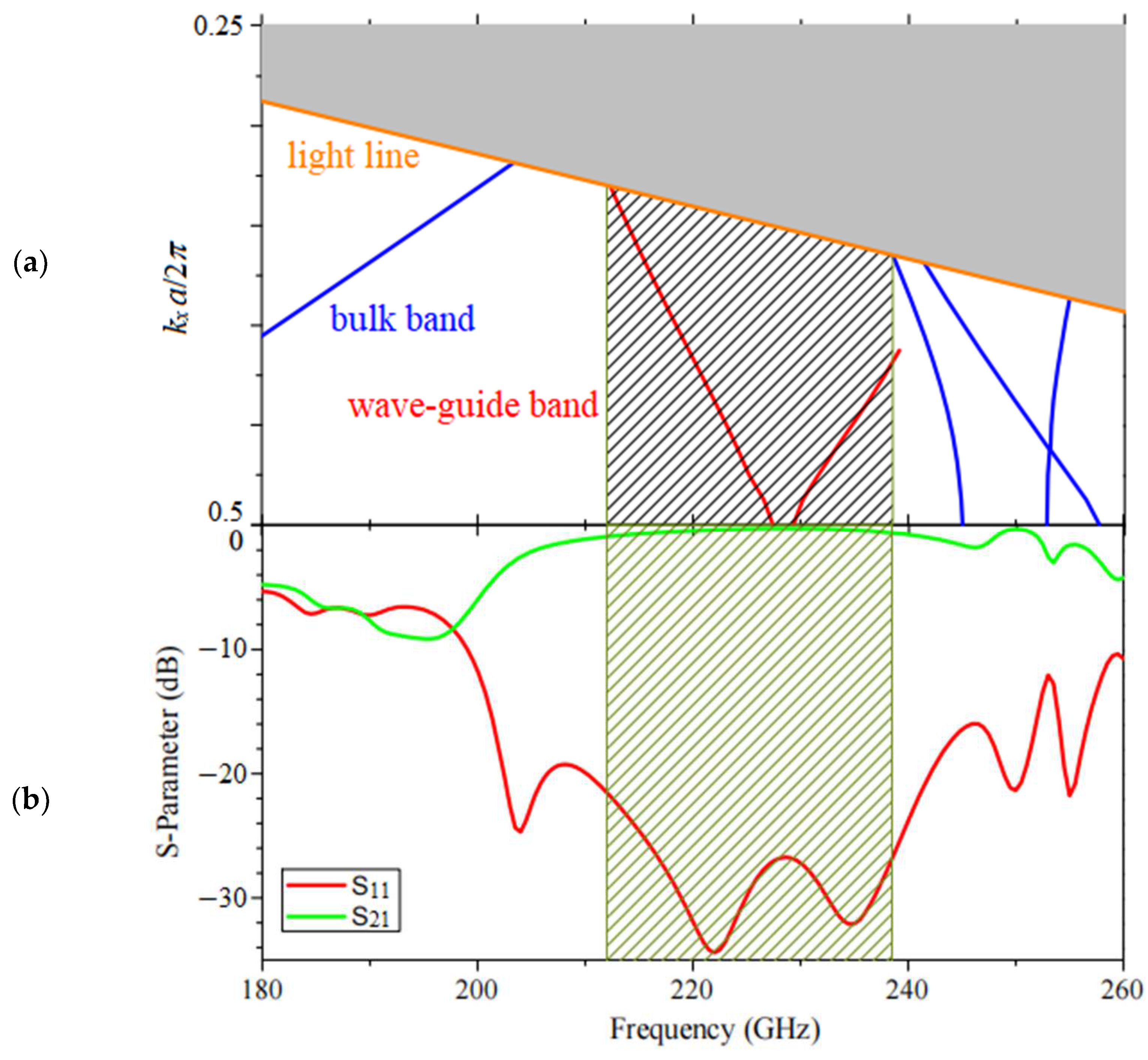
As depicted in
Figure 2, calculated through the eigen mode solution type commercial software HFSS, the projected band structure of PC the wave-guide in the Y-direction and the propagation characteristics of the PC slab wave-guide are shown in
Figure 2a. The shadow area is the leaky region under the light line (orange line), the red line is the wave-guided band, and the blue line is the bulk band of PCs. The EM wave can be completely confined and propagated in the PC wave-guide because of the PBG and the total internal reflection [
13]. In this situation, only the EM wave in the frequency of the bulk band (blue line) can propagate the PC structure, where the frequency range with no bulk band is PBG. After introducing the line defect, the wave-guided band (red line) appeared in the PBG, and the EM wave propagated in the frequency range of the wave-guide band. We had the wave-guide band covered with a section line, which included the working frequency of the PC wave-guide. The propagation characteristics of the PC wave-guide are shown in
Figure 2b, where S
21 is the transmission coefficient, and S
11 is the reflection coefficient. Under the wave-guide band frequency range from 0.212 to 0.238 THz, which is presented in the section line region, the transmission loss appears as low as 0.2 dB.
3. Design and Theory of PC Circulator
The nonreciprocal property of the circulator is based on MO materials. The permeability tensor [
μr] of MO materials is asymmetric under an external magnetic field, and the direction of EM waves propagate through changes in the Cartesian coordinate system, under an external magnetic field in the z-axis direction, and the permeability tensor of ferrites [
μr] is [
14]:
where the elements can be expressed as follows:
where
ω0 =
μ0γH0 is the precession frequency of the EM wave, and
ω =
μ0γMs. H
0 is the external magnetic bias field; 4
πMs is the saturation magnetization, and the gyro-magnetic ratio
γ = 1.759 × 10
11 (C/kg).
The radius of the cylindrical ferrite R can be approximately calculated as [
15]:
where
lf is the height of the cylindrical ferrite,
εr = 13.5 is the relative permittivity of the ferrite, and
x = 2.2 is the compromise value which determines the appropriate size of the ferrite radius. The working frequency here is
f0 = 0.225 THz, the saturation magnetization is 4
πMs = 3500 Gs, and the external magnetic bias field is
H0 = 600 Gs.
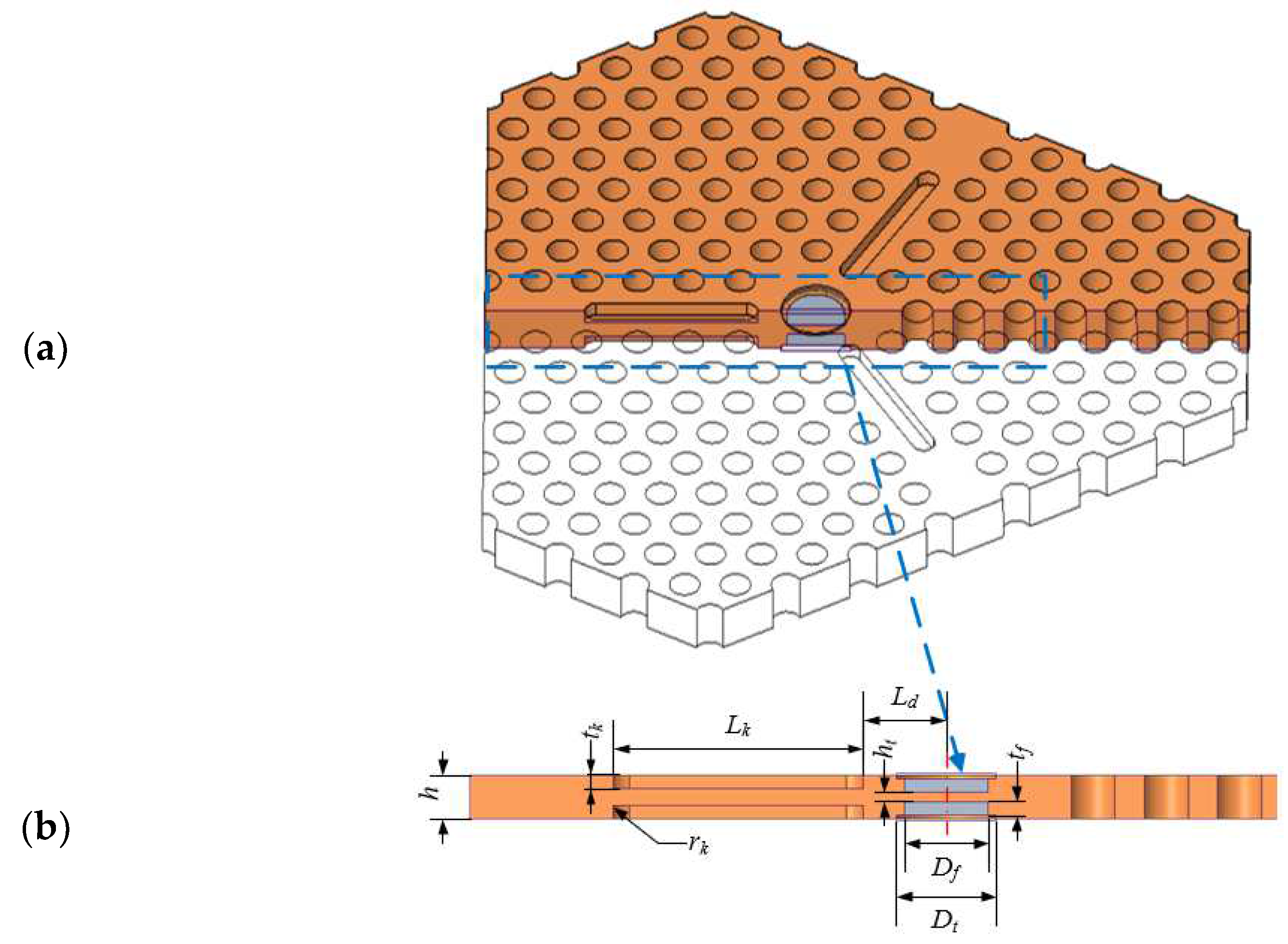
The MPC circulator is mostly based on the PC wave-guide. Theoretically, the PBG directly determines the working frequency of the circulator. Because of the photonic localization effect, only EM waves in the frequency range of PBG can be confined in the wave guide. As shown in
Figure 3a, a THz Y-shaped MPC slab circulator is constructed based on the TLPC hexagon slab. The Y-shape defect is introduced as the wave-guide structure, and two cylindrical ferrite disks inserted in the center Y-junction of the wave-guide work as a resonator. Outside the ferrite disks, there are two circle counterbores machined and covered with copper-clad to confine the EM wave from escaping in the vertical direction. In
Figure 3b, the partial cross-section view of the circulator with detailed dimensions is presented.
Similar to the ridge gap wave-guide, there are three key slots similar to grooves that are machined on the PC wave-guide, which is used as an impedance converter according to the external matching broadening method and improves the performance of the circulator. All the dimension parameters that refer to the designed MPC circulator are summarized in
Table 1.
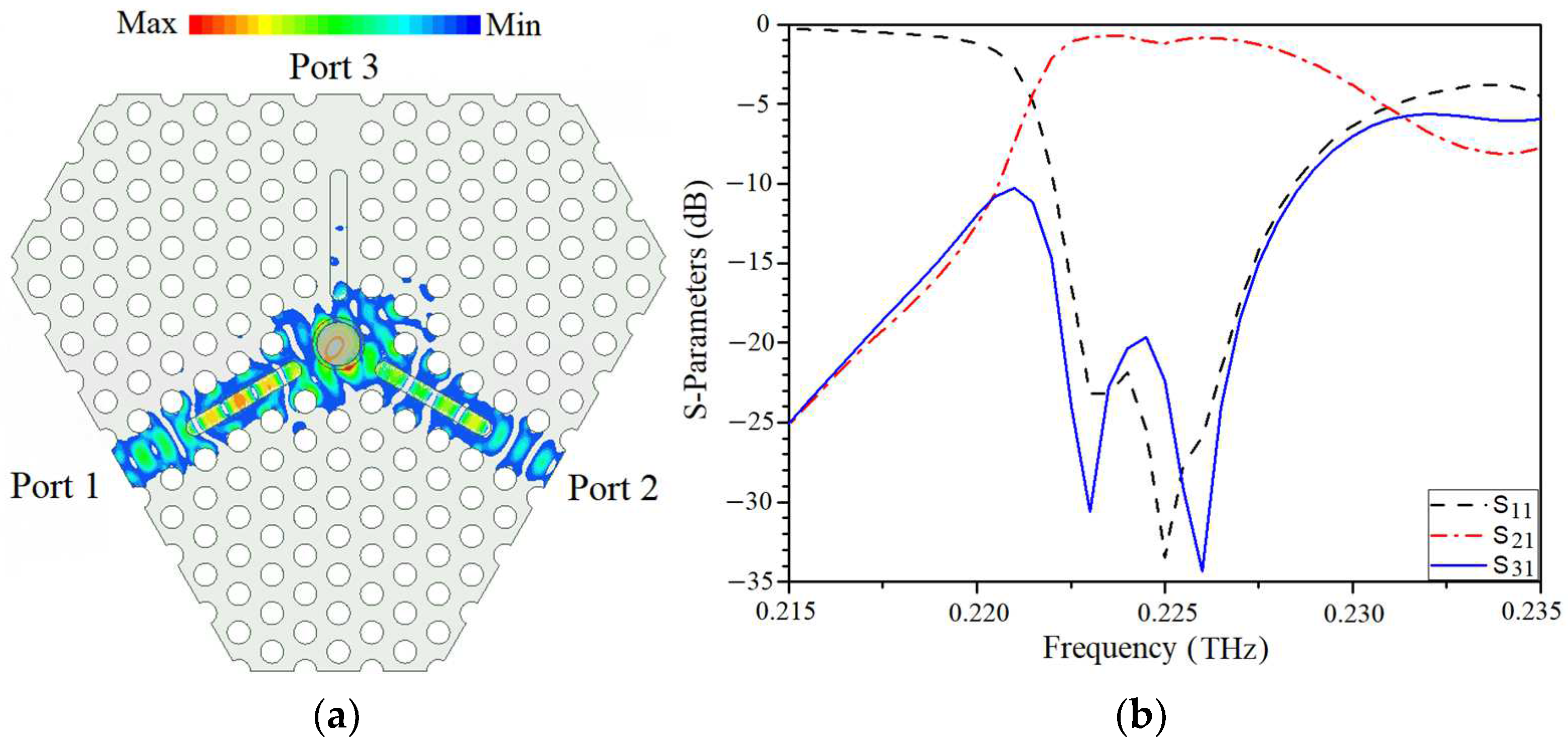
When simulated by FEM using software HFSS, the three ports are excited by the wave port, moreover. Since the MPC circulator is simply covered by air, an air box is made to cover the top and down area and is set to the radiation boundary. The transmission characteristics of the THz wave Y-shaped MPC circulator is shown in
Figure 4.
Figure 4a shows the electric field distribution of the circulator under the center frequency, the field launched from Port 1 (input port) is almost transmitted to Port 2 (output port) with 120 degrees rotation of propagation direction, and Port 3 (isolation port) is isolated. The S-parameter of the THz wave Y-shaped MPC circulator is depicted in
Figure 4b, which shows that near the center frequency of 0.225 THz, the isolation and reflectance of the designed MPC circulator are better than 20 dB, and the insertion loss is better than 1 dB, with a 5 GHz working bandwidth.
4. Conclusions
This work envisaged a novel THz circulator based on the MPC slab. Different from the pre-existed PC circulator using a metal shell to fix the dielectric post array and confine the EM wave from escaping in the vertical direction, the envisaged circulator was constructed based on a PC slab without metal coating on the entire surface. In the THz wave, the size of the PC circulator was so tiny that it was difficult to guarantee the machining accuracy, especially for that which needs a complex assembly. The design of the MPC circulator based on the air hold PC slab structure can greatly simplify the assembly complexity; at the same time, the tiny size and compact structure also made it easier for integration. Moreover, there is no necessary extra PEC cover shell, so we can extremely reduce Ohmic loss.
The transmission characteristics of the PC wave-guide and MPC circulator were analyzed and numerically simulated by FEM under the three-dimensional model using the software HFSS. There is a PBG of the designed PCs near the center frequency 0.225 THz, and the EM wave can be transmitted stably in the line defect PC wave-guide within the designed frequency range. The circulator is constructed by introducing a Y-shaped line defect wave-guide and MO materials into PCs. On the Y-shaped line defect wave-guide, several key slots were introduced, working as an impedance transformer to expand the bandwidth. In the designed working frequency 0.212–0.238 THz, the isolation and reflectance were better than 20 dB, and the best insert loss was as low as 1 dB. In an actually fabricated circulator, the tolerance of dimensional and material parameters influences the results, which still need fine-tuning in the manufacturing process. The compactness of the MPC circulator structure appears to be adequate for a large-scale integrated system. Considering the wide bandwidth and low loss characteristics of the MPC circulator, having it based on the MPC slab structure is a promising approach to generate a circulator at THz and an even higher frequency.
Author Contributions
Conceptualization, W.H. and D.Z.; writing—original draft preparation, B.X.; writing—review and editing, Y.W. and B.H.; supervision, G.S. All authors have read and agreed to the published version of the manuscript.
Funding
This research was funded by the Foundation for Distinguished Young Talents in Higher Education of Guangdong (2018KQNCX215), Shenzhen Science and Technology Program (JCYJ20200109105415835), and Shenzhen Science and Technology Program (KQTD20200820113046084).
Institutional Review Board Statement
Not applicable.
Informed Consent Statement
Not applicable.
Data Availability Statement
Not applicable.
Conflicts of Interest
The authors declare no conflict of interest.
References
- Tsuruda, K.; Fujita, M.; Nagatsuma, T. Extremely low-loss terahertz waveguide based on silicon photonic-crystal slab. Opt. Express 2015, 23, 31977–31990. [Google Scholar] [CrossRef] [PubMed]
- Malekabadi, A.; Charlebois, S.A.; Deslandes, D.; Boone, F. High-Resistivity Silicon Dielectric Ribbon Waveguide for Single-Mode Low-Loss Propagation at F/G-Bands. IEEE Trans. Terahertz Sci. Technol. 2014, 4, 447–453. [Google Scholar] [CrossRef]
- Xu, B.; Zhang, D.; Zeng, X.; Wang, Y.; Dong, Z. Magnetic photonic crystal circulator based on gradient changing width waveguide. Optik 2019, 185, 132–137. [Google Scholar] [CrossRef]
- He, W.; Donaldson, C.R.; Zhang, L.; Ronald, K.; Phelps, A.D.R.; Cross, A.W. Broadband amplification of low-terahertz signals using axis-encircling electrons in a helically corrugated interaction region. Phys. Rev. Lett. 2017, 119, 184801. [Google Scholar] [CrossRef] [PubMed] [Green Version]
- Ghiasi, M.; Hamidi, E.; Kashani, F.H. A Novel Method for Backward Wave Cancellation of Traveling Wave Tube Amplifier Using Ferrite Material. IEEE Trans. Plasma Sci. 2020, 48, 3001–3006. [Google Scholar] [CrossRef]
- Fan, F.; Chen, S.; Chang, S.J. A Review of Magneto-Optical Microstructure Devices at Terahertz Frequencies. IEEE J. Sel. Top. Quantum Electron. 2017, 23, 1–11. [Google Scholar] [CrossRef]
- Dmitriev, V.; Silva, S.L.M.D. Ultra wideband THz graphene four-port circulators. Microw. Opt. Technol. Lett. 2020, 62, 112–117. [Google Scholar] [CrossRef]
- Dmitriev, V.; Castro, W.; Melo, G.; Oliveira, C. Controllable graphene W-shaped three-port THz circulator. Photonics Nanostruct.-Fundam. Appl. 2020, 40, 100795. [Google Scholar] [CrossRef]
- Shalaby, M.; Peccianti, M.; Ozturk, Y.; Morandotti, R. A magnetic non-reciprocal isolator for broadband terahertz operation. Nat. Commun. 2013, 4, 1558. [Google Scholar] [CrossRef] [PubMed] [Green Version]
- Fan, F.; Xiong, C.Z.; Chen, J.R.; Chang, S.J. Terahertz nonreciprocal isolator based on a magneto-optical microstructure at room temperature. Opt. Lett. 2018, 43, 687–690. [Google Scholar] [CrossRef] [PubMed]
- Xu, B.; Zhang, D.; Wang, Y.; He, W. Characterization of millimeter wave photonic crystal circulator with a ferrite sphere. Results Phys. 2022, 34, 105315. [Google Scholar] [CrossRef]
- Li, Y.; Zhang, D.; Luo, M.; Yang, Q.; Fan, F.; Chang, S.; Wen, Q. Terahertz magneto-optical response of bismuth gadolinium substituted rare-earth garnet film. Opt. Express 2021, 29, 23540–23548. [Google Scholar] [CrossRef] [PubMed]
- Fujita, M.; Takahashi, S.; Tanaka, Y.; Asano, T.; Noda, S. Simultaneous inhibition and redistribution of spontaneous light emission in photonic crystal. Science 2005, 308, 1296–1298. [Google Scholar] [CrossRef] [PubMed]
- Zhang, D.G.; Lin, W.G. A new design method of H-plane waveguide circulator. Int. J. Infrared Millim. Waves 1988, 9, 173–177. [Google Scholar] [CrossRef]
- Yung, E.K.; Zhang, D.G.; Wong, R.S. A novel waveguide Y-junction circulator with a ferrite sphere for millimeter waves. IEEE Trans. Microw. Theory Tech. 1996, 44, 454–456. [Google Scholar] [CrossRef]
| Disclaimer/Publisher’s Note: The statements, opinions and data contained in all publications are solely those of the individual author(s) and contributor(s) and not of MDPI and/or the editor(s). MDPI and/or the editor(s) disclaim responsibility for any injury to people or property resulting from any ideas, methods, instructions or products referred to in the content. |
© 2023 by the authors. Licensee MDPI, Basel, Switzerland. This article is an open access article distributed under the terms and conditions of the Creative Commons Attribution (CC BY) license (https://creativecommons.org/licenses/by/4.0/).


