1. Introduction
Optical wireless communications (OWCs) have garnered significant attention from both industry and academia because of their numerous advantages over radio-frequency (RF) communication systems. With the increasing demand for high capacity to support emerging applications in networks and Internet of Things (IoT) devices, OWC is expected to be a promising candidate technique for future 6G networks [
1]. By using light-emitting diodes (LEDs) or laser diodes (LDs) as transmitters, OWC is immune to RF interference, can provide higher security, potentially offers higher data rates, and consumes less power compared to RF systems [
2]. However, it is important to note that LEDs are non-coherent and nonlinear optical devices with a peak transmitted power constraint.
In recent times, orthogonal frequency division multiplexing (OFDM) has gained substantial popularity in bandlimited optical systems, owing to its resistance to inter-symbol interference (ISI) and high spectral efficiency [
3]. However, the adoption of conventional OFDM schemes designed for RF communication in OWC systems is not straightforward because of the non-coherent nature of light emitted from LEDs. Among the various optical OFDM schemes, DC-biased optical OFDM (DCO-OFDM) stands out as one of the most widely used options, primarily because of its simplicity [
4]. In DCO-OFDM, a constant bias is added to the bipolar OFDM signal to ensure non-negativity. Another approach, asymmetrically clipped optical OFDM (ACO-OFDM), eliminates the need for adding a DC component by utilizing only the odd frequency subcarriers for modulation [
5]. However, ACO-OFDM sacrifices half of its bandwidth efficiency. Alternatively, unipolar OFDM (U-OFDM), or Flip-OFDM, transmits positive and negative signals in separate adjacent frames. Nevertheless, U-OFDM utilizes an extra signal frame in each OFDM symbol, leading to a spectrum efficiency that is only half that of DCO-OFDM [
6].
Given the inherent peak power constraint associated with light sources, it becomes imperative to account for the presence of clipping distortion, which can exert a pronounced adverse effect on system performance. To address this challenge, contemporary research has introduced a novel solution known as clipping-enhanced optical OFDM (CEO-OFDM), tailored specifically for power-constrained OWC systems [
7]. CEO-OFDM employs an ingenious approach, whereby the clipped portion of the signal is transmitted via extra signal frames. This strategic utilization of the clipped portion effectively mitigates the nonlinear distortion stemming from peak power constraints. Derived from both analytical assessments and simulation experiments, CEO-OFDM2 exhibits superior performance, achieving a lower biterror rate (BER) or a higher data transmission rate, compared to existing state-of-the-art OFDM schemes. Nevertheless, it is important to acknowledge that the incorporation of extra signal frames necessitates a wider bandwidth, thereby introducing additional noise components at the receiver. Furthermore, the reconstruction of the intended data involves the amalgamation of multiple signal frames, a process that compounds the noise from each frame, ultimately amplifying the cumulative effective noise.
The current research focus in the field of optical OFDM revolves around addressing the issues related to clipping distortions caused by the nonlinear behavior of light sources and improving receiver design. Recent studies have explored various strategies to tackle these challenges. One approach involves optimizing power allocation for individual subcarriers in DCO- and ACO-OFDM systems, with the goal of maximizing the signal-to-noise ratio (SNR) while considering clipping distortions [
8]. Furthermore, researchers have introduced variations of DCO- and ACO-OFDM, such as adaptively biased OFDM and superposition-based nonlinearity mitigation for ACO-OFDM, to mitigate clipping distortions [
9,
10].
To address receiver-related challenges, novel methods have been developed to combat clipping distortions. Unlike pre-processing techniques applied at the transmitter, these algorithms are designed specifically for the receiver. For example, an iterative decision method was proposed for ACO-OFDM, which improves the demodulation process by accurately estimating the sign information of the original unclipped signal, thereby enhancing overall performance [
11]. Additionally, researchers introduced a semi-deterministic approach to mitigate clipping noise in DCO-OFDM systems [
12]. Recently, a new decision-directed signal reconstruction (DDSR) algorithm with optimal thresholds for mitigating clipping noise was proposed in optical OFDM systems [
13]. Theoretical analysis and simulation results verified that using optimal thresholds proposed in [
13] significantly enhanced the DDSR algorithm’s performance. Another receiver-based algorithm using a nonlinear technique to mitigate the clipping distortion in optical OFDM system was studied [
14], in which the clipped signal could be extracted using a nonlinear process. These advancements represent significant progress in the ongoing efforts to optimize optical OFDM systems, especially in the presence of challenging nonlinear effects caused by the characteristics of light sources.
In this paper, we introduce a novel interference degradation algorithm, referred to as the tolerance-aided interference degradation (TAID) algorithm, designed for implementation at the receiver end. The primary objective of TAID is to mitigate both clipping distortion and partial additive noise inherent in the received signals. Specifically, when employing the CEO-OFDM technique, the proposed algorithm operates by introducing a decision tolerance at the receiver stage. This tolerance value is strategically chosen to assess the signals received in the initial two signal frames, determining whether the clipped portion transmitted in the extra frame is essential for accurate reconstruction. Through a judicious selection of an appropriate decision tolerance, our algorithm significantly reduces additive noise while concurrently compensating for clipping distortion, thereby enhancing the overall signal quality and system performance.
The remainder of the paper is organized as follows. The problem descriptions are discussed in
Section 2. In
Section 3, we describe the proposed TAID algorithm and analyze its performance. The numerical results of TAID and the performance comparison with DCO-, ACO-, and CEO-OFDM are discussed in
Section 4. The paper is concluded in
Section 5.
3. Principles of Tolerance-Aided Interference Degradation Algorithm
This section provides an introduction to the principles underpinning the proposed TAID algorithm. It is important to note that TAID is exclusively designed for received signal processing, and thus, we adhere to the CEO-OFDM signal structure at the transmitter. To facilitate a comprehensive understanding of the principles governing TAID and to enable a thorough performance analysis, we sequentially delve into discussions related to the transmitted signal, the channel model, and the received signal model.
3.1. Transmitted Signal Model
For the sake of brevity and clarity in notation, we conduct our analysis within the confines of a single OFDM symbol duration. In our pursuit of high spectral efficiency, we employ
M-ary quadrature amplitude modulation (
M-QAM). For the
ith subcarrier, we denote the modulated data as
, where
M signifies the size of the modulation constellation. It is essential to emphasize that, in order to maintain a real-valued OFDM signal,
and
must constitute a conjugate pair, with
N denoting the total number of subcarriers, as articulated in [
17]. Following the
N-point inverse fast Fourier transform (IFFT) operation and the parallel-to-serial conversion, the
mth sample of the OFDM symbol can be expressed as
where
c is the modulation index controlling the scale of the transmitted signal magnitude. It is worth noting that
c can be subject to optimization, effectively striking a balance between signal power and the mitigation of clipping distortion arising from the peak radiation power constraint imposed by the light sources.
At the transmitter, the bipolar signal
is reformed to be unipolar by the CEO-OFDM rules. Then, the
nth sample of the transmitted signal is denoted [
7]:
where
which represents the nonlinear response of the light sources with the peak power constraint. The response of the working zone is modeled as a linear function of the input current.
is the radiation power limit.
3.2. Channel Model
OWC systems usually use LDs, LEDs, and infrared (IR) diodes as light sources for signal transmission. In addition to the peak transmitted power constraint, it is important to recognize that these light sources inherently exhibit low-pass characteristics. Typically, the behavior of these light sources can be effectively approximated through the utilization of first-order low-pass filter models, with the parameters often estimated using pilot signals within OFDM systems, as elucidated in [
18].
In this paper, we emphasize that channel estimation lies outside the scope of our research focus. We make the fundamental assumption that the channel has been accurately estimated, and for the purpose of compensating channel losses on each subcarrier, a single-tap equalizer is deployed. In the context of OFDM systems, the mitigation of intersymbol interference necessitates the inclusion of a cyclic prefix (CP), a standard component that can be meticulously designed based on prevailing channel conditions, as elaborated in [
17,
19,
20]. For the purposes of this article, our analysis is centered on the system following the extraction of the cyclic prefix at the receiver stage. To streamline both the calculations and the ensuing analysis, we simplify our modeling by assuming an ideal channel with unity loss.
3.3. Received Signal Model and Effective Noise Models
At the receiver, the incoming optical signals undergo a conversion process into electrical signals, followed by discrete-time sampling. The representation of the
nth sample of the received discrete-time electrical signal can be expressed as
where
represents the responsivity of the photodetector (PD), which denotes the optical-to–electrical power conversion ratio.
is the additive noise, including thermal and shot noises. In this paper, we assume
is a Gaussian white noise with zero mean. Its variance can be calculated as
, where
is the transmitted
M-QAM symbol rate and
is the single-sided noise power spectral density.
is the
nth sample of the discrete-time end-to-end system impulse response, which can be pre-estimated. The operation “∗” represents the discrete-time convolution.
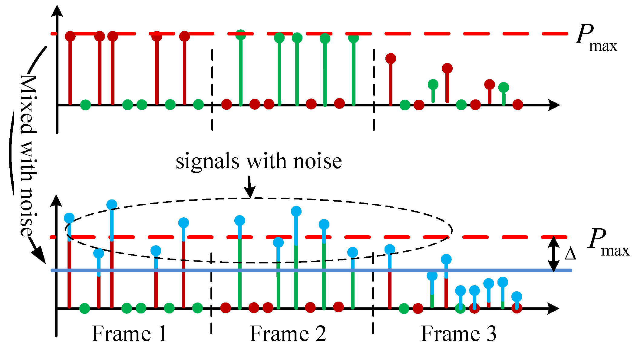
Drawing upon the CEO-OFDM signal model, the received signal in one OFDM symbol contains three signal frames. Each frame is mixed with the additive noise, and the peak power clipping distortion happens in frame 3 only. Since the additive noise is mixed in all three signal frames, simply combining the three frames dramatically amplifies the effective noise. As shown in
Figure 3, with the interference of the noise mixed in frames 1 and 2, the signals that should have been clipped at
are greater or less than the peak power.
To address this challenge, we introduce a decision tolerance parameter denoted as . By applying decision criteria to each received sample within frames 1 and 2, we can effectively reduce the impact of additive noise. Specifically, if the signals in frames 1 and 2 surpass the threshold of , we enforce their value to be . Consequently, the corresponding signals in frame 3 are regarded as the clipped portion that necessitates combination during the demodulation process. Conversely, when the signals in frames 1 and 2 fall below the threshold of , it is assumed that they have not been distorted by the peak power limit, and their associated clipped portion within frame 3 is deemed unnecessary.
A comprehensive block diagram illustrating this decision process is provided in
Figure 4 as a detailed representation, where
denotes the unit sign function. It is imperative to recognize that the choice of the decision tolerance parameter
can significantly impact the trade-off between the noise introduced in frame 3 and the interference stemming from clipping distortion within frames 1 and 2.
After applying the proposed TAID algorithm, the
nth sample of the reconstructed signal is represented as
where
and
.
is the discrete-time unit step function.
is a decision function controlled by the defined tolerance
, which is represented as
Then, after the
N-point fast Fourier transform (FFT) of the reconstructed signal
, the demodulated
M-QAM symbol on the
ith subcarrier can be modeled as
where
and
represent the clipping coefficient and the channel frequency magnitude of the
ith subcarrier, respectively.
is the Fourier transform of
, which is estimated using the pilot signals. Based on Bussgang’s theorem, the clipping coefficient is a function of the modulation index, which can be calculated from [
17]:
where
is the complementary error function, which is defined as
.
is a nonlinear function that represents the peak clipping distortion, represented as
3.4. Effective Noise Model and the Performance Analysis
In (
9),
represents the effective additive noise after reconstructing the received signal using TAID, which is modeled as a combination of the peak power clipping noise, additive noise at the receiver, and the noise of using the decision tolerance. In this paper, we derive
as
where
,
, and
represent the clipping noise, effective additive noise, and noise introduced by the decision tolerance, respectively.
Despite CEO-OFDM being applied, it is noteworthy that the transmitted signals remain susceptible to peak clipping distortion. The severity of this peak power constraint-induced distortion escalates with the modulation index, denoted as
c, which governs the scale of the transmitted signals. To evaluate the system performances using TAID, we adopt an approach wherein we represent the clipping distortion as an additional source of noise. This distortion is characterized as a Gaussian-distributed random variable with a zero mean. Its variance can be calculated as in [
15], which is a function of the modulation index, as
where
is the variance of
.
By implementing the proposed TAID algorithm, the reduction of additive noise across the three signal frames is remarkably achieved. Leveraging the central limit theorem (CLT), the effective noise subsequent to the application of the TAID algorithm can be suitably approximated as a Gaussian random variable characterized by a zero mean. The variance of this effective noise is intricately linked to the decision tolerance, which is a composite of two constituent components, represented as
In Equation (
14),
pertains to the scenario where the transmitted signals within frames 1 and 2 have not undergone peak clipping. However, in practice, the influence of noise can lead to instances where these signals, upon reception, exceed the defined decision threshold of
. In such situations, it becomes necessary to artificially consider these signals as having been clipped, requiring us to enforce a value of
for the received signals within frames 1 and 2. Consequently, the introduction of interference stemming from the decision tolerance must be taken into account, and
can be calculated as
where
and
(a,b;c;z) represent the Gamma function and the regularized hyper-geometric function, respectively [
21].
In Equation (
14),
corresponds to the scenario wherein the transmitted signals within frames 1 and 2 are set to
, indicating that the corresponding signals within these frames have been subject to hard clipping. In practice, because of the presence of noise, the signals declared as
within frames 1 and 2, when received, may actually fall below the threshold of
. Consequently, as per the TAID algorithm, the associated signals within frame 3 must be excluded during the data reconstruction process. This introduces peak clipping distortion, the variance of which, denoted as
, is calculated as
where
represents the greatest integer less than or equal to
x.
For a certain modulation index and a pre-designed decision tolerance, the received signal-to-interference plus noise ratio (SINR) for the
ith subcarrier can be represented as a function of
c and
, which is
where
denotes the power of the additive noise, and it can be computed as
. Here,
signifies the noise spectral power density, and
B corresponds to the receiver’s bandwidth. Given the SINR, we can approximate the bit error rate (BER) for the
ith subcarrier by using the expression from [
22], that is
which is a function of the modulation index and the detection tolerance. Based on (
18), the optimal modulation index and the decision tolerance can be found to minimize the system’s BER by solving the following objective function:
In (
19), the optimal modulation index
and the optimal decision tolerance
can be obtained by using the exhaustive search method for the sake of convenience. Since the objective function is non-convex and contains hyper-geometric terms, numerical results are derived. For this problem, the exhaustive search method is a feasible way to find the optimal solution for the two parameters,
c and
.
3.5. Computational Complexity Analysis
In this section, we conduct an analysis of the computational complexity of the proposed algorithm, which is directly related to processing time. To ensure a fair comparison of computational complexity, we evaluate it based on the transmission of an equivalent number of data. In the case of DCO-OFDM, a transmitter employs an N-point IFFT module, resulting in a computational complexity of . In contrast, ACO-OFDM uses only half of the available subcarriers for data modulation, leading to a computational complexity of when modulating the same data volume as DCO-OFDM.
Considering the proposed TAID algorithm transmits the same signal structure as CEO-OFDM, which involves sending two additional signal frames compared to DCO-OFDM, its computational complexity matches that of CEO-OFDM, which can be expressed as .
It is worth noting that, for the proposed TAID algorithm, the receiver is responsible for setting the decision tolerance. Therefore, only a decision process is necessary, eliminating the need for the additional complexity associated with CEO-OFDM.
4. Numerical Results and Comparison
In this section, we present the numerical results pertaining to the system performance when employing the proposed TAID algorithm. Unless explicitly stated otherwise, we utilize the parameters as outlined in
Table 1, which is typical for indoor spaces and used as a benchmark [
7,
15]. To facilitate an equitable comparison of system performance, we assume a channel loss factor of one, as it does not significantly impact the analysis and ensures consistency across the test scenarios. Given the inherent characteristics of light sources, we employ a first-order low-pass filter to emulate the transmitter. As per preliminary investigations, the 3 dB bandwidth of such filters typically spans a range of several tens of megahertz for commonly used lighting LEDs, as documented in [
23]. Conversely, LDs and IR LEDs often exhibit larger bandwidths, reaching approximately a few hundred megahertz, as confirmed by studies such as [
24,
25,
26]. In this study, we evaluate scenarios encompassing both large and small bandwidths. Furthermore, it is imperative to acknowledge that the constraints imposed by the light source’s driving current lead to limitations of the peak transmitted optical power. This constraint results in the clipping of signals with magnitudes exceeding the power constraint, thereby introducing nonlinear distortion into the system.
In this study, we employ the direct current–biased optical OFDM (DCO-OFDM), asymmetrically clipped optical OFDM (ACO-OFDM), and clipping-enhanced optical OFDM (CEO-OFDM) techniques as the benchmark for evaluating system performance. To ensure an equitable and meaningful comparison, identical parameters are adopted across all tested techniques. For DCO-OFDM, a bias is introduced with a magnitude of
, striking a balance between mitigating peak power and zero clipping. It is important to note that the transmitted data symbol rate provided in
Table 1 reflects the effective data symbol rate, accounting for spectral utilization efficiency considerations. Comparing the performances of DCO-, ACO-, and CEO-OFDM and the proposed algorithm at the same transmitted data rate, we can calculate the required bandwidths for the compared techniques as
From this relationship, the ACO- and CEO-OFDM require twice and three times larger bandwidth than DCO-OFDM, respectively.
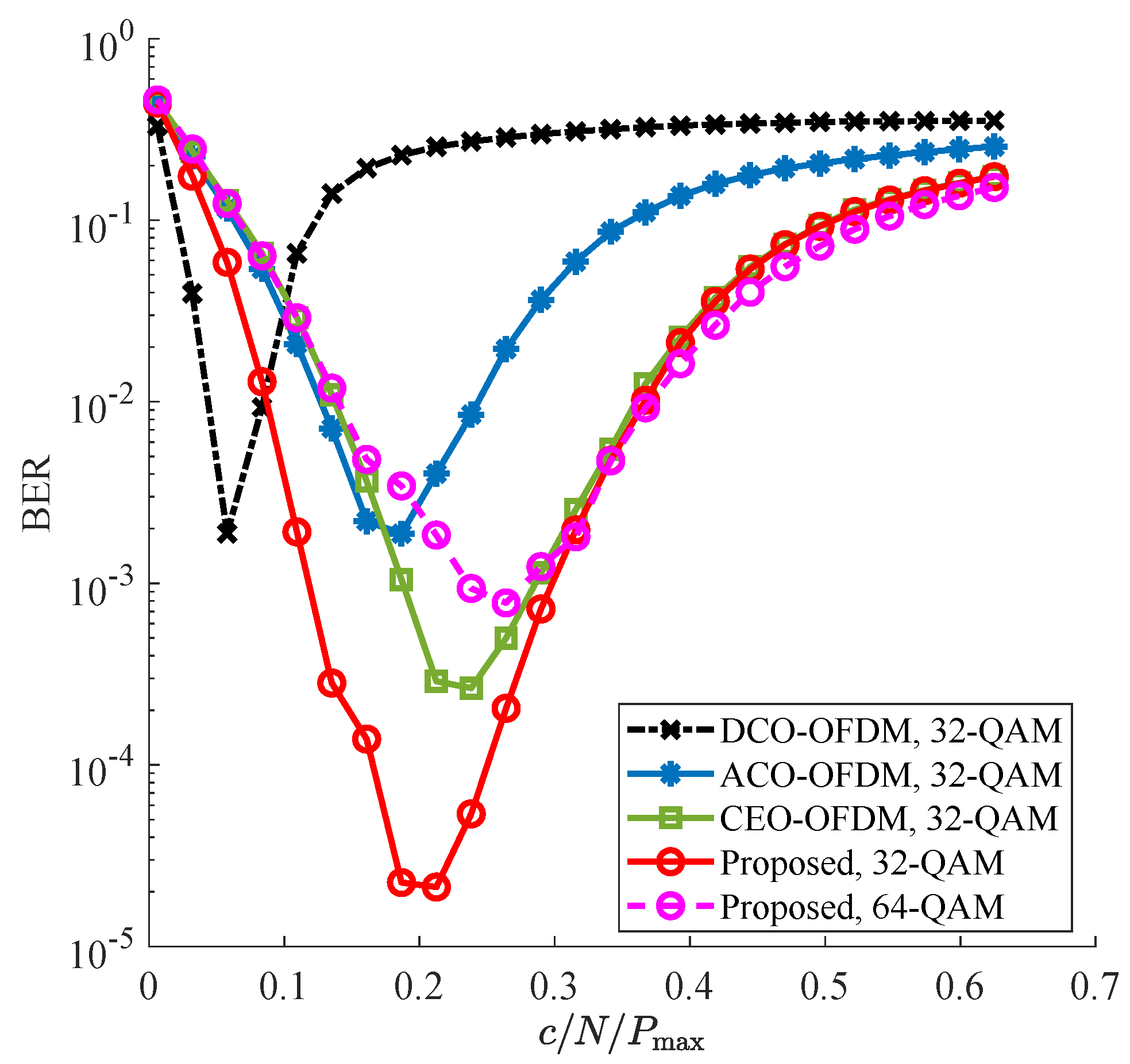
Figure 5 presents a comparative analysis of BER performances among the proposed TAID algorithm, DCO-OFDM, ACO-OFDM, and CEO-OFDM techniques operating through an ideal channel, as the modulation index increases. For the proposed TAID algorithm, the figure showcases the minimum BER attained for various modulation indexes, with this minimum achieved through an exhaustive search for the optimal decision tolerance parameter
. In general, as the modulation index increases, the BER performance improves across all the discussed techniques. However, a notable trend emerges whereby a further increase in signal scale results in more pronounced clipping distortion. When the clipping distortion becomes dominant over the additive noise, the BER performance deteriorates. Because of ACO-OFDM’s utilization of only odd-numbered subcarriers for signal modulation, its bandwidth efficiency is reduced by half compared to DCO-OFDM. Consequently, ACO-OFDM necessitates twice the bandwidth of DCO-OFDM for equivalent data throughput. Similarly, CEO-OFDM requires three times the bandwidth of DCO-OFDM for an equitable comparison. The numerical results depicted in this figure demonstrate that the proposed algorithm consistently achieves the lowest BER among the discussed techniques while employing the same modulation constellation size. Moreover, the proposed algorithm exhibits a broader dynamic modulation index range than those of DCO-OFDM, ACO-OFDM, and CEO-OFDM, maintaining a BER below
. Our findings reveal that, with 64-QAM, the proposed algorithm yields a comparable best BER performance to DCO-OFDM and ACO-OFDM using 32-QAM. Given that the effective transmitted data symbol rate remains consistent for fair comparison, the proposed algorithm attains a
higher data rate than the other compared techniques while achieving a similar BER.
As discussed in this paper, CEO-OFDM and the proposed technique require the widest bandwidth among the compared techniques. In the numerical results illustrated in
Figure 5; we specifically compare the outcomes obtained with 64-QAM for the proposed algorithm against those with 32-QAM for DCO-OFDM and ACO-OFDM. Given the capability to achieve a comparable best BER performance through modulation index adjustments, we can deduce that the bandwidth efficiency of DCO-OFDM, denoted as
, is twice that of ACO-OFDM, denoted as
. Furthermore, we observe that
is approximately 2.5 times that of the proposed algorithm, denoted as
, based on the equation
.
In the context of a bandlimited channel, we extend our analysis to compare the BER performances of the proposed algorithm with DCO-OFDM, ACO-OFDM, and CEO-OFDM. The corresponding numerical results are presented in
Figure 6. Given that ACO-OFDM and CEO-OFDM exhibit lower bandwidth efficiency compared to that of DCO-OFDM, their BER performances deteriorate when targeting the same transmitted data rate. Leveraging the benefits of the proposed TAID algorithm, the effective added noise is substantially reduced, leading to an enhanced SINR with TAID. Consequently, the BER performance surpasses that of DCO-OFDM, ACO-OFDM, and CEO-OFDM when utilizing the given parameters.
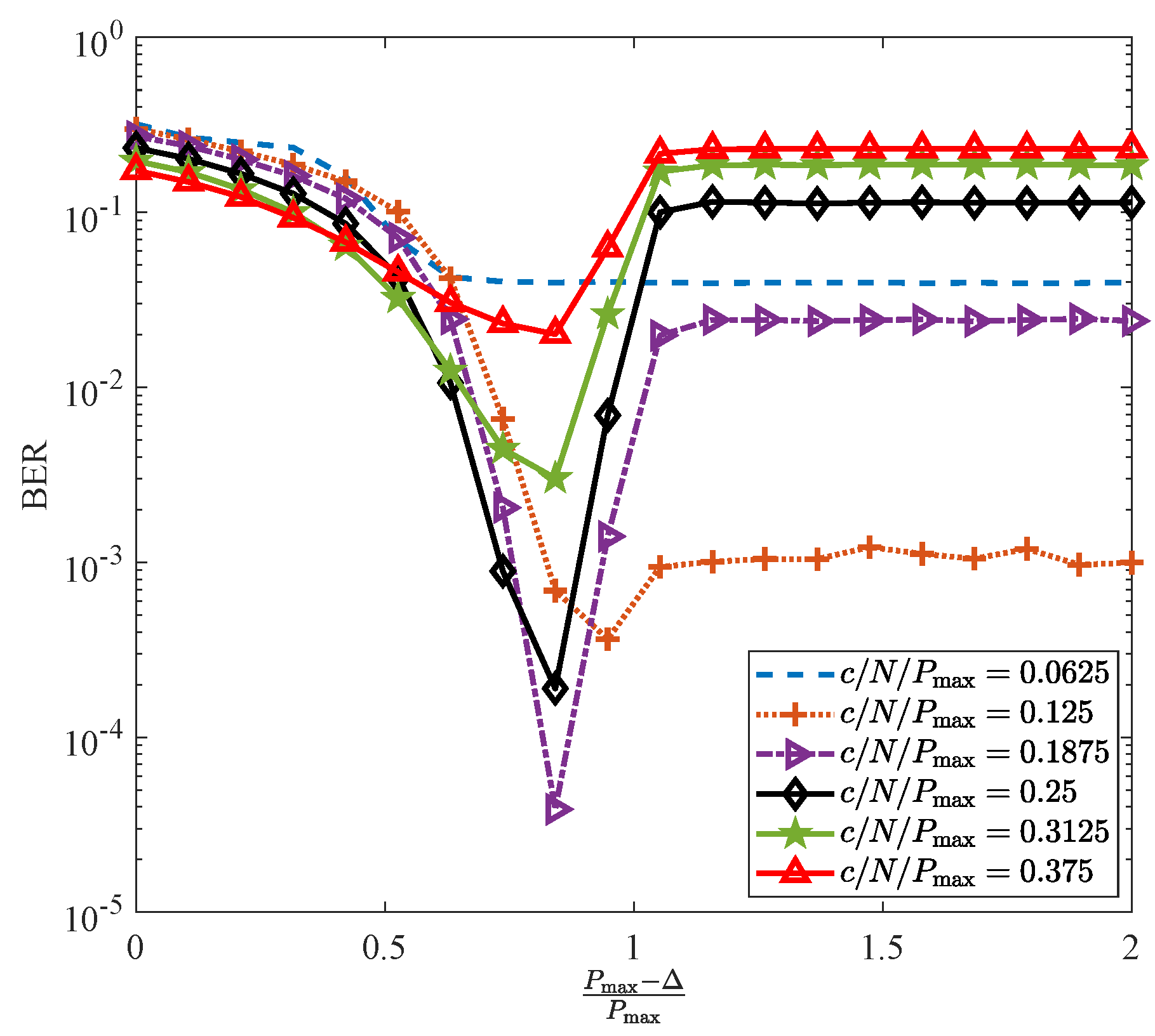
The decision tolerance stands as a crucial design parameter that demands careful adjustment to attain optimal BER.
Figure 7 presents the BER performances for various modulation indexes with increasing values of
. In this depiction, we introduce the ratio
to denote the separation between the peak power and the decision threshold. When
, the decision threshold is lower than
. Across all scenarios, we observe a trend wherein as the ratio escalates, the BER performance improves. This behavior is attributed to the fact that the decision tolerance, as it increases, effectively mitigates a portion of the additive noise. However, when the ratio is further increased, bringing
closer to
, it leads to the introduction of more added noise, resulting in a deterioration of the BER.
In this paper, we delve into the relationship between the scale of the transmitted signal and the optimal decision tolerance. The numerical results, depicted in
Figure 8, elucidate the evolving pattern of the ratio
as the transmitted signal scale increases.
From this figure, it becomes apparent that the optimal ratio for achieving the best BER exceeds one when the signal scale is small. This observation aligns with the fact that, for small-scale signals, the impact of peak power clipping can be marginalized, allowing us to position the decision threshold beyond the peak power value. This strategic placement effectively aids in noise reduction. Conversely, when the transmitted signals exhibit a relatively larger scale, the presence of peak power clipping distortion becomes non-negligible. Consequently, it necessitates a smaller decision threshold, falling below the peak power level, in order to effectively mitigate a portion of the added noise. This empirical result underscores the fact that, with a smaller peak power constraint imposed on the light sources, a lower value of the ratio is needed to achieve optimal BER.
5. Conclusions
In this article, we present a novel tolerance-aided interference degradation algorithm tailored for power-constrained optical OFDM systems. At the receiver end, we introduce a decision tolerance and establish criteria to effectively mitigate both clipping distortion and additive noise. In the context of CEO-OFDM, this algorithm aids in determining whether the signals received in the first two signal frames, which are subsequently re-transmitted in the extra frame, are essential for data reconstruction. Furthermore, it enables compensation for clipping distortion. Our extensive analysis and numerical results showcased that, by judiciously selecting the decision tolerance, the bit error rate (BER) performance can be significantly enhanced by two orders of magnitude compared to conventional DCO-, ACO-, and CEO-OFDM techniques. Additionally, our proposed algorithm boasts a broader dynamic modulation index range, ensuring a BER below .
Utilizing the specified parameters, our algorithm, employing 64-QAM modulation, achieves a comparable best BER performance as DCO-, ACO-, and CEO-OFDM with 32-QAM. Consequently, it delivers a remarkable higher data rate than the other aforementioned techniques. This substantial performance enhancement positions TAID as a promising solution for power-constrained optical OFDM systems, offering superior BER performance and data rate efficiency.


