Article

Bidirectional Atmospheric Channel Reciprocity-Based Adaptive Power Transmission

School of Information Science and Engineering, Shenyang University of Technology, Shenyang 110870, China
*
Author to whom correspondence should be addressed.
Photonics 2023, 10(10), 1067; https://doi.org/10.3390/photonics10101067
Submission received: 25 August 2023 / Revised: 17 September 2023 / Accepted: 18 September 2023 / Published: 22 September 2023

Abstract

:
In atmosphere free-space optical communication (FSO) systems, the scintillation effect produced by turbulence effects increases the bit error rate (BER) of the communication system and reduces the system’s performance. However, a high correlation of turbulent noise occurs in the two transmission channels when a signal transmitted in the bidirectional atmospheric channel with channel reciprocity. The performance of the FSO system can be increased by extracting channel state information (CSI) in forward transmission and using adaptive power technology to reduce turbulence in inverse transmission. In this research, we propose a bidirectional atmospheric channel reciprocity-based adaptive power transmission (CR-APT) technique that lowers the bit error rate of the transmitted signal by using the CSI of the relevant channel. To verify the effectiveness of the technique, a bidirectional atmospheric channel with various turbulence intensities is built in the simulation program, along with various background sounds to vary the channel reciprocity, and the impact of reciprocity on signal transmission is examined. The simulation findings demonstrate that adaptive power transmission with high reciprocity is excellent under the weak turbulence condition, and its future development is promising.

1. Introduction

Free-space optical communication has received a lot of interest recently due to the prevalence of data-traffic issues and its benefits of a small antenna size, no requirements of authorization, and high bandwidth [1]. The turbulence effect and background noise are the two primary features of the noise impact brought by the atmospheric channel in actual FSO communication system implementations. Due to atmospheric turbulence brought on by temperature, humidity, and other factors, a wireless optical signal sent over the atmosphere would have undesirable consequences such as beam expansion, beam drift, light-intensity flicker, and more [2]. The optical signal will be distorted by the background noise that solar radiation produces [3,4]. Due to the turbulence effect and background radiation noise, the received signal has a high bit error rate [5], and the FSO communication system’s performance is below optimal [6].
Researchers have investigated a variety of effective communication techniques to deal with the adverse impacts brought on by atmospheric turbulence. Multibeam light was proposed to be used for information transmission in FSO links in the literature [7,8], However, multibeam means multichannel, and the pointing inaccuracy is not insignificant. Multimode aperture diversity reception was studied in the literature [9,10] to minimize turbulence damage. This method was more effective, but the system was less stable. According to the literature [11], optical phase conjugation (OPC) was used in FSO communication to mitigate the turbulence effect and correct for signal distortion. This technique could effectively improve the performance of FSO communication, but it might cause inter-channel crosstalk and channel power imbalance. To decrease the system’s emissive power and the likelihood of a system failure, ref. [12] proposed using statistical estimation of the approximate misalignment angle of multiple incident light beams. However, this method was less frequently used in weak turbulence scenarios. Ref. [13] came with a technique for high-dimensional coded communication employing polarization differential phase shift keying with the use of turbulence-resistant vector beams, but this method had not yet been used in practice. Refs. [14,15] provided an in-depth study of compensation schemes using orbital angular momentum (OAM) in atmospheric turbulence, but OAM links are less effective in long-range communication.
Additionally, the adaptive transmission method works well as a turbulence effect channel compensating technique. The rate adaptive transmission strategy, which had excellent results in communication transmission but was more challenging to implement, had been proposed in the literature [16]. The authors of ref. [17] replaced channel state information with the adaptive threshold decision (ATD) by using the low-pass characteristics of atmospheric turbulence to extract the instantaneous intensity. The quantization voltage of the judgment signal was used in ref. [18] as the judgment threshold for an adaptive threshold decision system. Ref. [19] utilized an adaptive linear prediction filter for CSI prediction and ATD using predicted CSI. Although FSO systems of refs. [17,18,19] based on adaptive approaches had higher performance and reduced loss, they all disregard the impact of background noise. Most studies have concentrated on unidirectional atmospheric channel transmission, although bidirectional atmospheric channel transmission has also drawn more interest since the introduction of Shapiro’s original concept of channel reciprocity [20]. Bidirectional atmospheric channel transmission consists of two transmitters placed at the ends of the link with the same axial symmetry emitting beams. This method can send, receive, and send information in a very short period of time, which can be approximated by the same channel turbulence state. To lessen the negative effects of the turbulence effect and enhance the performance of the transmission system, the channel state information in instantaneous transmission may be measured and extracted in transmission [21]. Then, the channel compensation scheme can be employed. Since there are currently fewer methods that combine adaptive transmission and reciprocity [22], the bidirectional atmospheric channel that uses adaptive transmission needs further study.
In this paper, we propose a bidirectional atmospheric channel reciprocity-based adaptive power transmission technique. According to the reciprocity property of a bidirectional atmospheric channel, while CSI estimation is performed at the receiving end of forward transmission using the received signal, adaptive power transmission is used at the transmitting end of inverse transmission in order to lower the BER of the transmitted signal. To test the usefulness of the technique, a bidirectional atmospheric channel with various turbulence strengths is built in the simulation software, and various background sounds are introduced to the channel to vary the channel reciprocity. Based on experimental data gleaned via simulation, the impact of reciprocity on adaptive power transfer is researched, and the effectiveness of adaptive power transfer technology is assessed. In order to examine the viability of this technique in various contexts, Fixed threshold decision (FTD) and conventional ATD techniques are included in the simulation studies for horizontal comparison.

2. Theoretical Analysis

We break down the theoretical analysis into two sections in this paragraph. In Section 2.1, we provide a comprehensive formulation of the mathematical model of the modeling using the bidirectional atmospheric turbulence transmission channel, and in Section 2.2, we meticulously describe the flow of the proposed adaptive power transmission technique based on the reciprocity of bidirectional atmospheric channels.

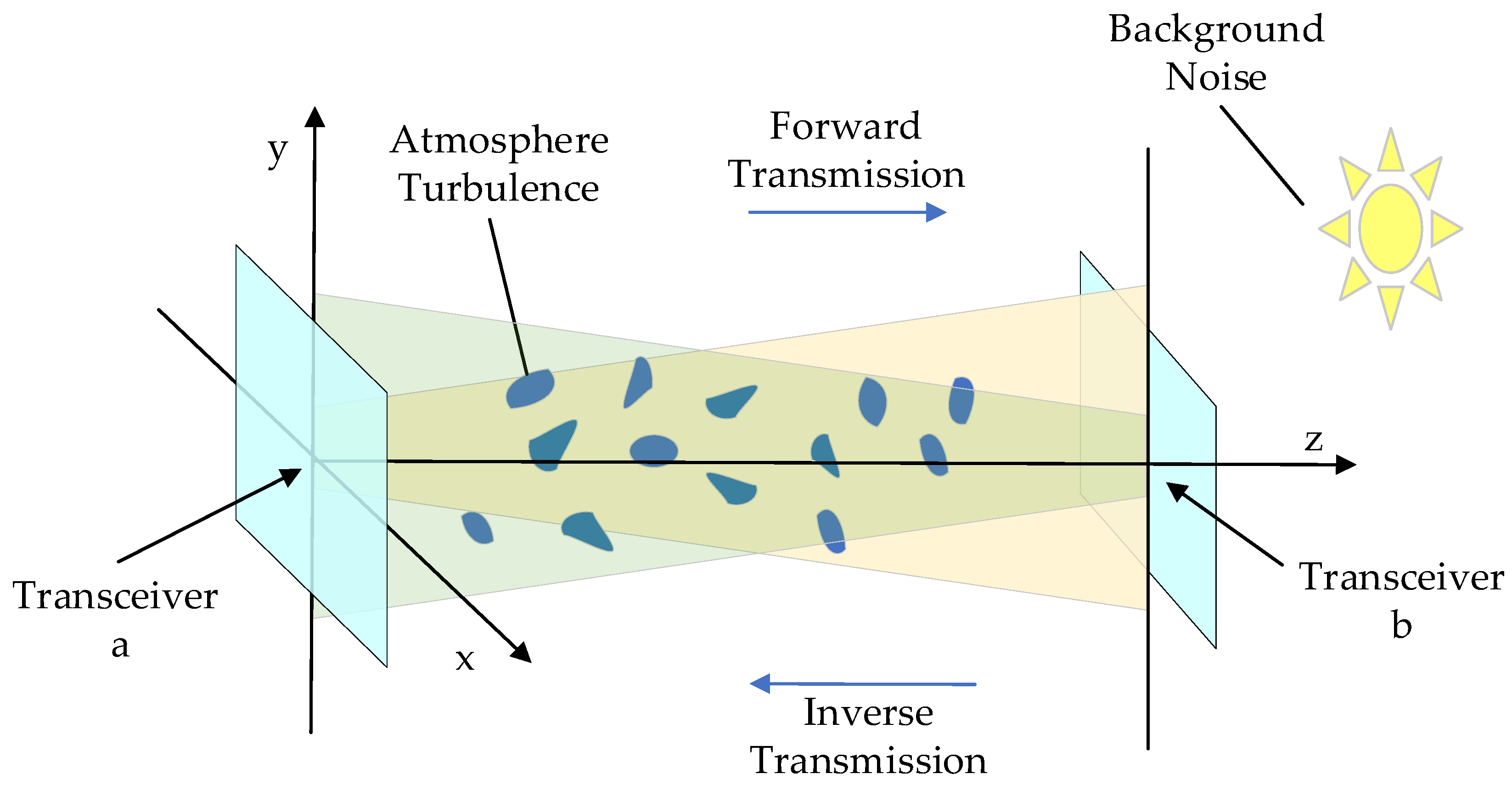
2.1. Bidirectional Atmospheric Transmission Channel Model

The two transceivers a and b are allocated to receive a signal when they goes through a bidirectional optical wireless channel with atmospheric turbulence in the bidirectional atmospheric channel model utilized in this work. At the same end of the link are the two transceivers, a and b. In a short period of time, the send–receive–send transmission process may be completed by the transceivers situated at the two ends of the connection with the same axis symmetry, as schematically depicted in Figure 1.
We refer to process of transmitting a symbol that go from point a to point b and from point b to point a, respectively, as forward transmission and inverse transmission. The received signal of RF at the receiving end in forward transmission may be expressed as the following under the assumption of intensity modulation and direct detection [23]:
R F = P L T S F + N ,
PL denotes the optical power of transmitting terminal, T denotes channel fading due to turbulence effects, SF is the transmitted symbol, and N is the independent zero-mean unit-variance Gaussian noise, where the intensity of the turbulent channel fading is represented by the scintillation index of σ 2 , which is defined as follows [24]:
σ F 2 = E [ T 2 ] E 2 [ T ] 1 ,
and the subscript F in Equation (2) denotes the forward transmitted scintillation intensity, and E[·] denotes the mathematical variance operation. The outgoing signals are not subject to the same background noise because of the various heights of the transceivers a and b, which might be reflected in the modeling as a high background noise in the inverse-transmission channel. Thus, according to Equation (1), the received signal of RI that is sent in the other way may be represented as
R I = P L C S I + N ,
where C tabulates the channel fading strength due to turbulent noise and background noise; meanwhile, SI denotes the transmitted symbol of inverse transmission. In additional, the channel reciprocity of ρ can be evaluated by the fading strength of the two channels [25], and it is defined as
ρ = cov ( C , T ) σ I σ F = E [ C T ] 1 ( 1 + σ I 2 ) ( 1 + σ F 2 ) ,
where σ n 2 ( n = F , I ) denotes the channel-fading variance in Equation (4) and cov(·) represents the covariance function. In contrast, the atmospheric turbulence channel simulation of the channel applied in this paper approximates a lognormal distribution; so, the correlation coefficient and scintillation index can be redefined [26]:
ρ ˜ = log ( 1 + ρ σ 2 ) log ( 1 + σ 2 )

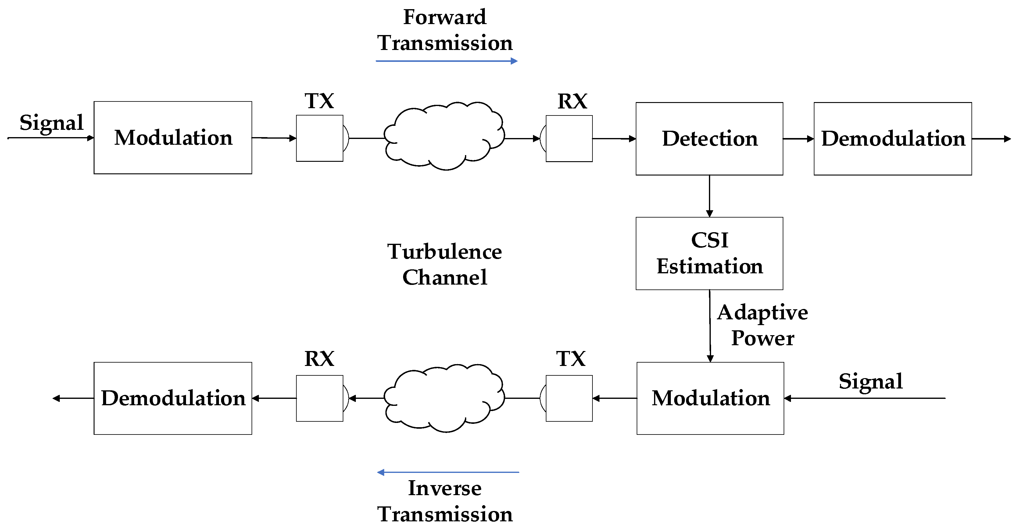
2.2. Adaptive Power Transfer System

In this research, we present an adaptive power transfer technique based on bidirectional atmospheric channel reciprocity. We discuss a point-to-point FSO communication system employing intensity modulation/direct detection On–Off Keying (OOK) modulation across turbulent channels in this approach due to the high complexity of phase or frequency modulation.
The system block diagram of the proposed adaptive power transfer approach is shown in Figure 2. In the bidirectional atmospheric channel, because the forward-transmission and reverse-transmission channel turbulence intensity are related, the CSI of the forward transmission channel can be extracted, and the signal power can be adjusted according to the known CSI in the reverse transmission, so as to achieve the purpose of suppressing turbulence and enhancing the communication quality. The specific process is as follows: at the transmitting end of the forward transmission, an amplitude 0 or 1 random pulse sequence is generated and sent into the turbulent channel after OOK modulation. At the receiving end, the state information of the channel is estimated based on the received signal, and the CSI reflecting the noise level of the channel is obtained; at this time, the receiving end of the forward transmission becomes the transmitting end of the reverse transmission. The OOK signal power is changed according to the known CSI, increasing the signal power at the poorer channel quality and decreasing the signal power at the better channel quality. After receiving the signal at the receiving end of the reverse transmission, the CSI estimation is performed again and the result is fed back to the transceiver. This can form a closed-loop control system so that the power of the transmitted signal can be dynamically adjusted according to the actual communication situation to improve communication quality.
While in the communication process, the received optical signals are converted into electrical signals under the influence of the noise generated during the detection process, which consists of thermal noise, dark current, and scattered particle noise. The noise produced by the photodetector can be characterized in the FSO communication system simulation engineering as additive white Gaussian noise (AWGN), whose noise amplitude is expressed in terms of the signal-to-noise ratio (SNR). The formula for SNR can be expressed as Equation (6), where Ps and Pn represent the effective power of the signal and noise, respectively.
S N R = 10 lg ( P s P n )
An analog-to-digital converter subsequently transforms the signal from current to digital signal. In order to acquire the digital received signal, the current is sampled at kT moments at k-bit intervals. The signal is split into two parts after sampling is complete, and the first portion can be used to determine the CSI of the forward transmission channel based on the amplitude shift brought on by turbulence. The second stage completes the demodulation before completing the CSI-based signal power modification. At this time, OOK signal has had their power adjusted, and the transmitting end serves as the receiving end for forward transmission while the receiving end serves as the transmitting end for inverse transmission. To demonstrate the effectiveness of the adaptive transmission technique in terms of the magnitude of the BER, the OOK signals are transmitted into the turbulent channel with background noise and are identified at the receiving end. The formula for BER is as follows [27]:
B E R = 0 f ( r ) Q ( r 2 ( N C + N P D ) ) d r
where f ( r ) is the probability density function (PDF) that obeys a normal distribution under turbulent conditions, Q(·) denotes the Gaussian function, NC denotes the noise present in the channel, and NPD denotes the noise generated by the photodetector in Equation (7). In summary, the adaptive power technique proposed in this paper can effectively mitigate the effects of noise in bidirectional atmospheric channels.

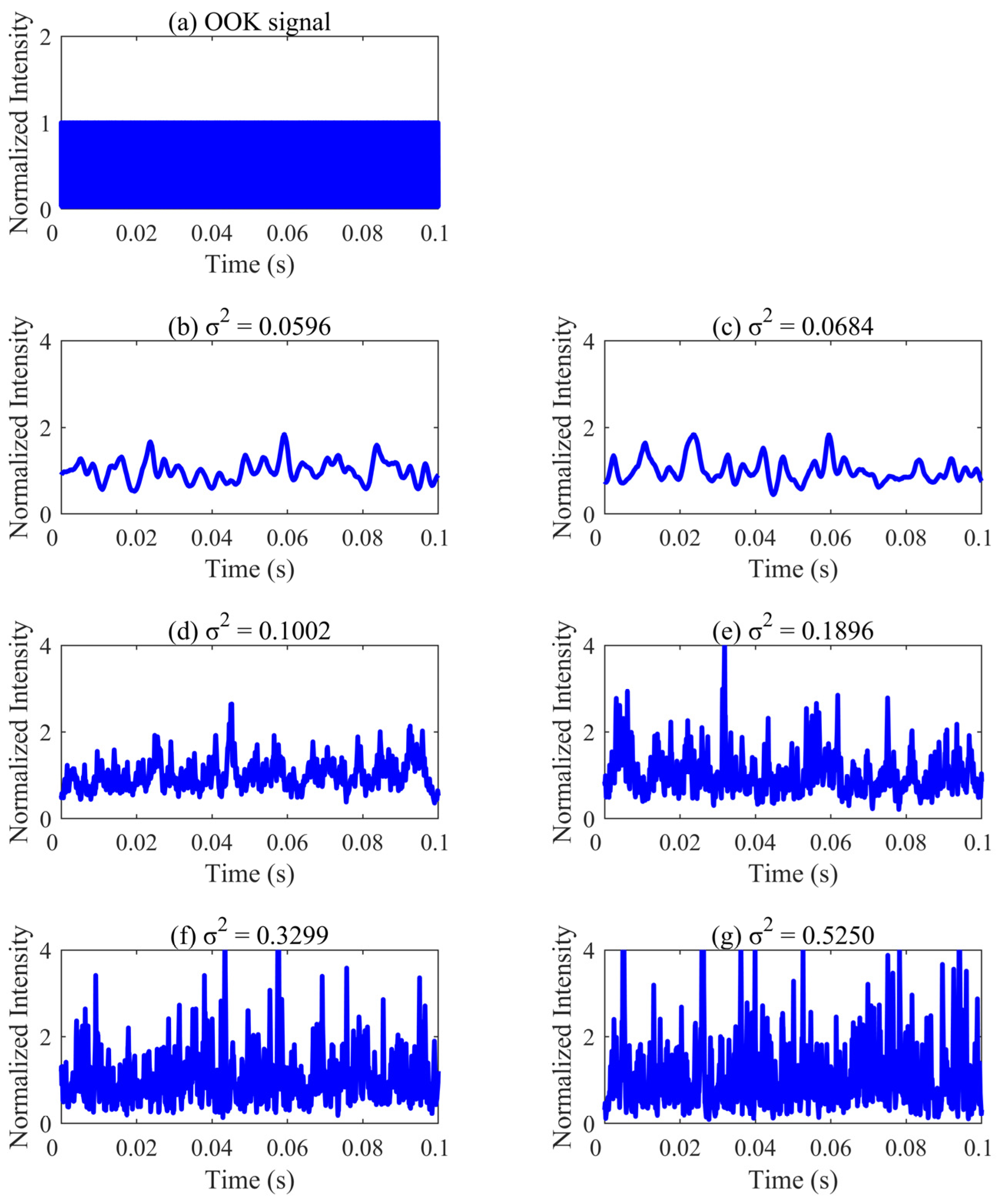
3. Simulation and Investigation

This section compares the performance of the FTD technique to the traditional ATD technique first. The BER performance was then presented and assesses after the adaptive power transfer system simulation occurs in the ideal scenario ρ = 1 of channel reciprocity without interference from background noise. Finally, to examine the impact of channel reciprocity on the adaptive power approach suggested in this research, the FSO system was simulated in the noisy state with various background noises. This simulation was conducted in MATLAB R2020b.

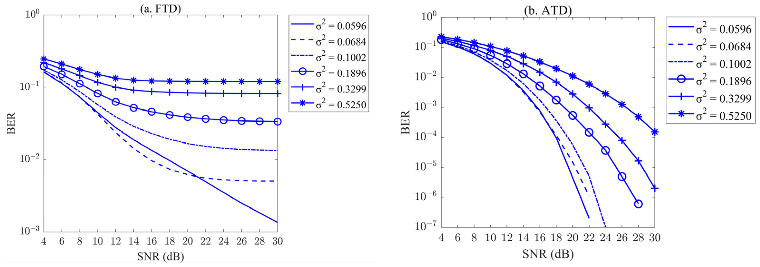
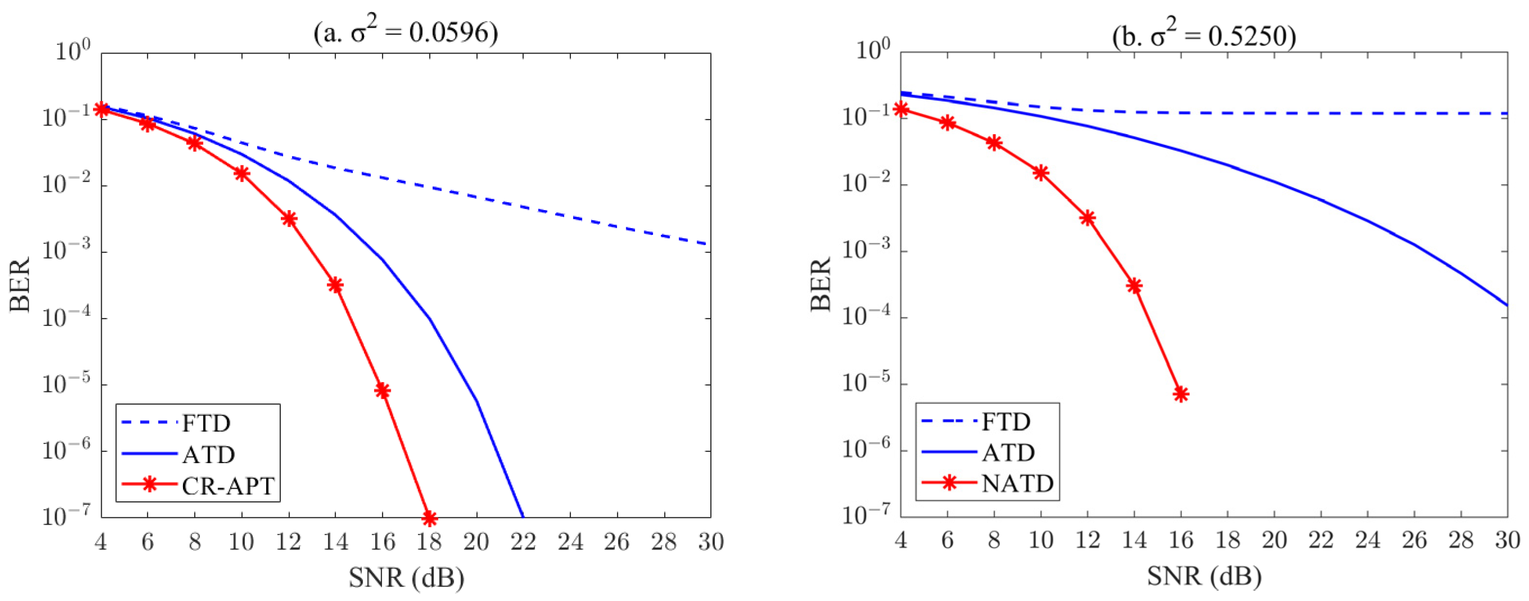
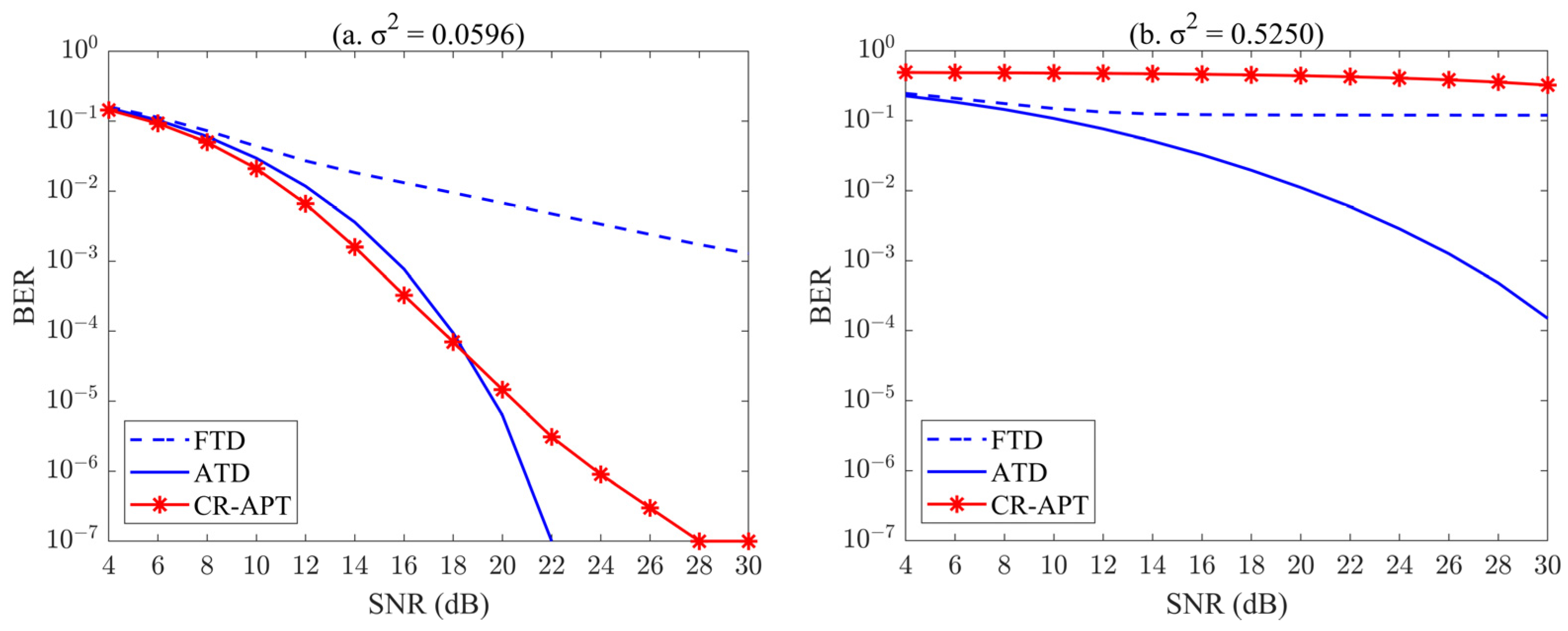
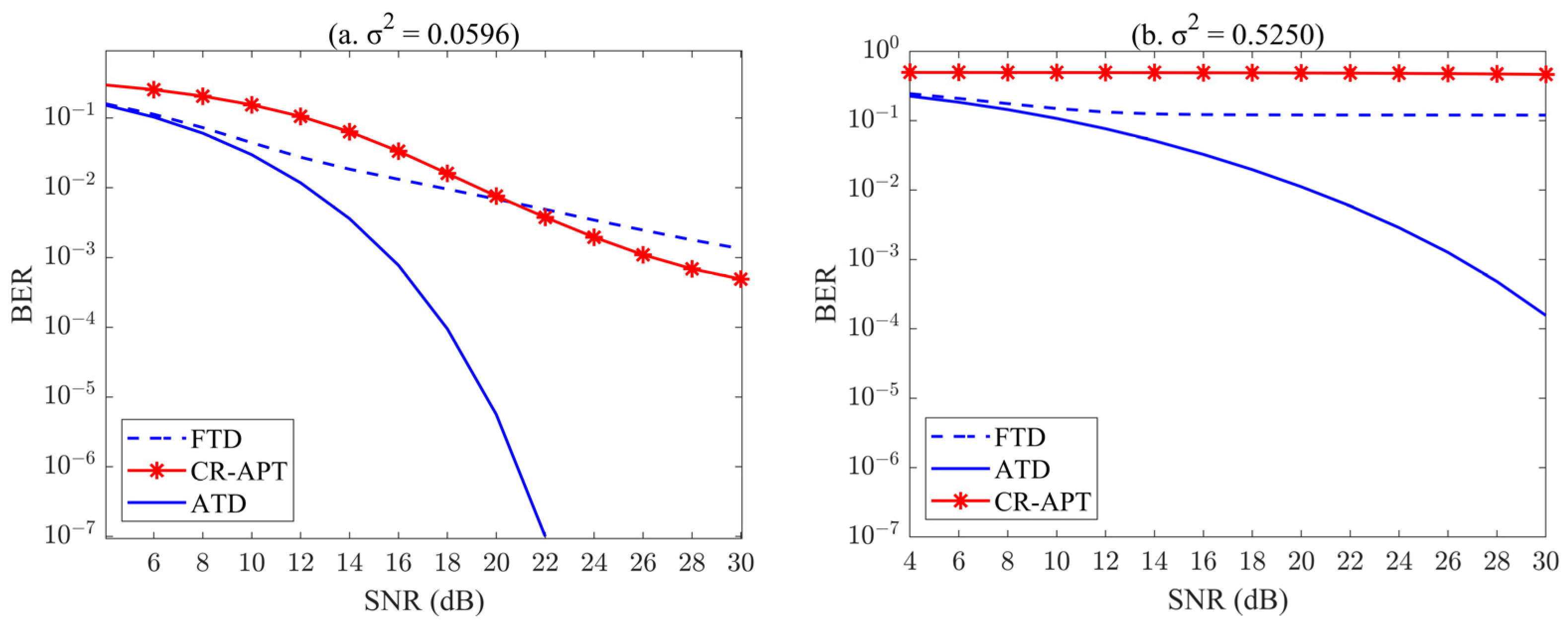
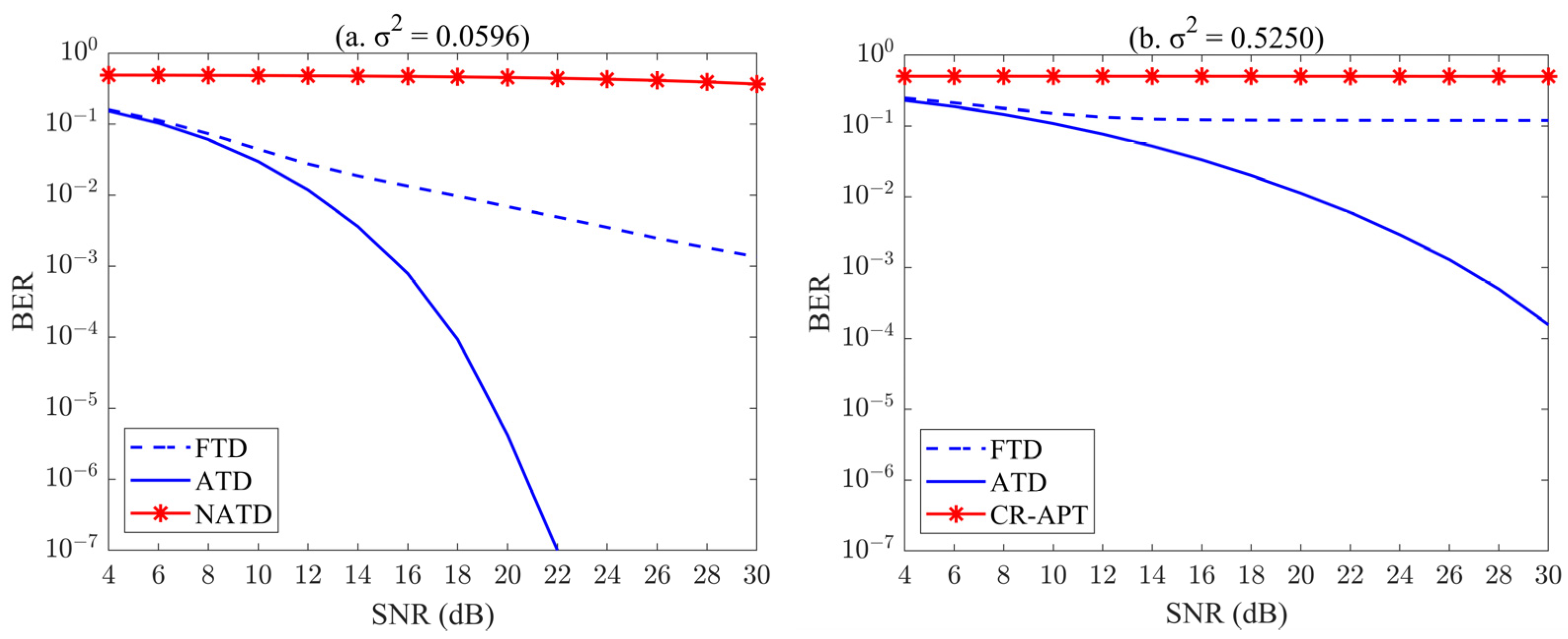
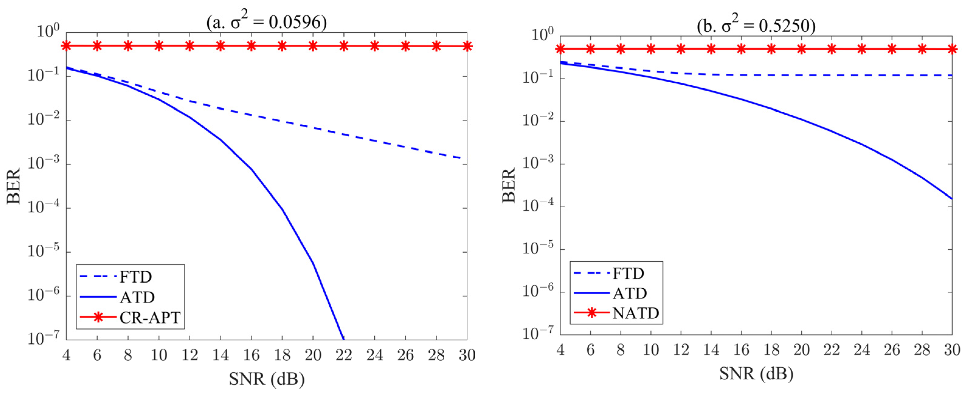
3.1. The BER Performance of Conventional FTD and ATD

Fixed threshold decision is frequently used in traditional communication technology because it has benefits like simple operation and intuitive results. In the FSO communication system, the FTD technique is to take the average fixed threshold for judgment after acquiring the channel state, as the name implies. Figure 3a shows the performance of the FTD under six-channel settings and various turbulence intensities. With the exception of channel circumstances σ 2 = 0.0596 , the BER performs nearly linearly across a range of SNRs. In other turbulent channel circumstances, the curve progressively reduced out at SNR > 16 dB, the BER gradually hit the lower limit, and as the severity of the turbulence rose, so did the BER’s lower limit. The BER was roughly 0.2, especially when the turbulence intensity reached 0.5250. The FTD approach cannot be used to transfer the signal properly in this situation. The reason for this is that the fixed threshold for averaging is no longer able to send the signal adequately when the turbulence is high since the optimal judgment threshold for signal transmission is changing over time.
When the turbulence intensity was significant, the FTD technique was unable to successfully transmit information. In order to complete transmission, adaptive transmission technology was created that modifies the judgment threshold in accordance with the signal that was influenced by turbulence. Additionally, Figure 3b illustrates how well the ATD approach performs in turbulent channels of varying intensities. As seen in Figure 3b, the ATD technology performed better than the FTD technology at transmitting signals in various turbulence scenarios, and the BER performance of the ATD transmission technology had increased by several orders of magnitude to 1 × 10 7 . The BER curves of ATD technology under various turbulence circumstances were comparable; as an illustration, in the turbulent channel of σ 2 = 0.1896 , the BER gradually declined as the SNR rose. Although conventional ATD performed better than FTD, the good BER at σ 2 = 0.5250 was only 1.5 × 10 5 , which still has room for improvement.
The OOK signal is utilized by the transmitter to control the optical signal transmission by switching the sinusoidal carrier on and off using a series of unipolar non-return-to-zero codes. To examine the performance of the signal over various turbulent channels, Figure 4 displayed the time domain performance of the real transmitted OOK signal. The MATLAB simulation software used the mean square error (MSE) function to calculate the error generated between the sent signal and the received signal more precisely. Figure 4 displayed the OOK signal’s time-domain performance as it moved through several turbulent channels.
In Figure 4, it could be observed that as the signal passed through the channel with higher turbulence intensity, the more intense the fluctuation of the time domain profile and the more severe the signal distortion. As shown in Figure 4b,c, the fluctuation of the time-domain curves embodied by the signal passing through the turbulence intensity and σ 2 = 0.0684 channels were minor, and it could be seen that the optical signal l was less affected by the turbulence noise. The numerical values of MSE were 0.047 and 0.051, along with the original signals that might be easily recuperated. As shown in Figure 4d,e, the time-domain curve produced distortion. For channels with scintillation intensity σ 2 = 0.1002 , the MSE value was 0.067, while for channels with σ 2 = 0.1896 , it was 0.114. Anti-noise measures must be used during communication in such channels in order to recover the signal transmission’s original content. As turbulence intensity rises, the signal ups and downs became more pronounced, and MSE values rose as a result. As for Figure 4e,f, when the signal passed through the turbulence channel, the amplitude fluctuated greatly, and when its MSE > 0.2, the signal distortion was serious.

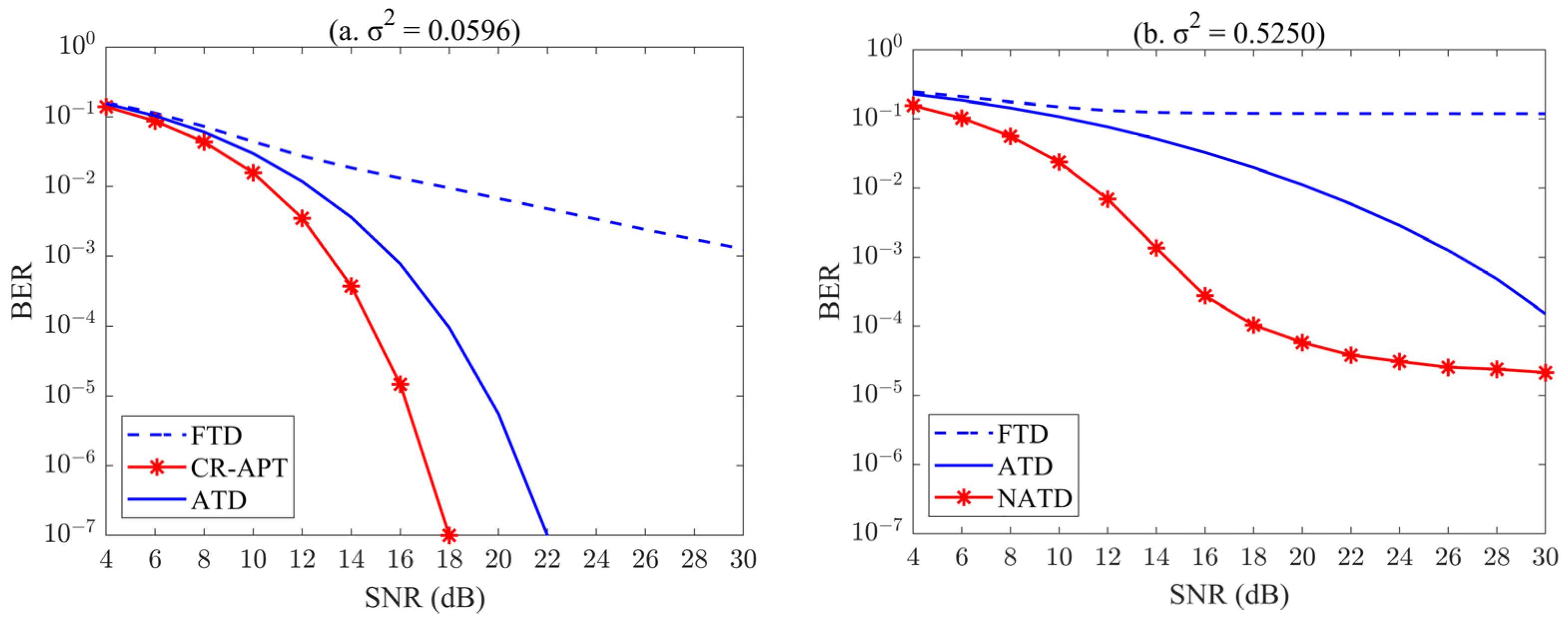
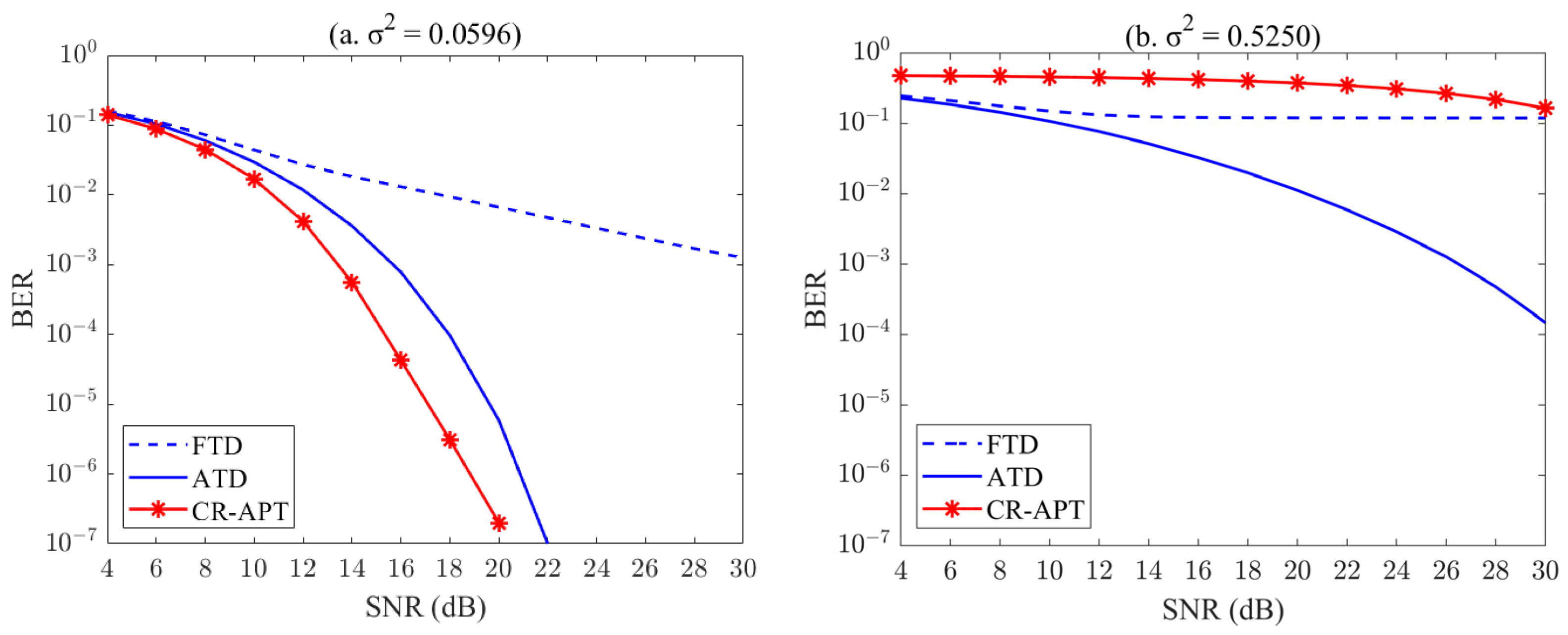
3.2. The BER Performance of Proposed Adaptive Power Transfer Technique

In the actual application of FSO communication systems, adaptive systems that change power based on the bidirectional atmospheric channel state information differ from FTD and ATD techniques in that they are sensitive to background noise produced by sunlight as well as other background light in addition to being affected by turbulence effects produced by the atmosphere. The AWGN function can be used to incorporate noise into system modeling, and in the following, Nb will be used in place of background noise to highlight how it differs from the thermal noise produced by the photographic detectors.
In a bidirectional atmospheric channel without the interference of background noise, it is ideal to utilize the same channel for forward and inverse transmissions, and the channel reciprocity is ρ = 1 . The performance of the FTD, ATD, and CR-APT transmission mechanisms was tested under these circumstances. In the meantime, two channels with turbulence intensities of σ 2 = 0.0596 and σ 2 = 0.5250 were chosen for simulated communication in order to compare the performance of each technique in various channels more succinctly and intuitively. As observed in Figure 5a, the CR-APT technique, under the ideal channel reciprocity of ρ = 1 , obtained the BER of 1 × 10 7 when SNR = 18 dB. CR-APT outperformed FTD and ATD while delivering better performance at lower SNR. In channels with a turbulence intensity of σ 2 = 0.5250 , the CR-APT technique had good performance and obtained a better BER at a lower SNR, in contrast to the FTD technique, which had failed and ATD technique that had produced a high BER. Figure 5 demonstrates that, under ideal circumstances, the CR-APT technique still performed well regardless of the kind of turbulence that the signal is delivered over.
Due to their varying heights and reception orientations, forward and inverse broadcasts in the FSO transmission system’s bidirectional atmospheric channel have various effects on the transmission channel when background noise is present. When the signal’s effective power is known, the background noise is assessed in terms of SNR, which can be learned from Equation (6) in Part II. The lesser the noise power, the bigger the SNR, and therefore, the larger the Nb. Consequently, the BER of the received signal and the turbulence channel reciprocity for forward transmission and inverse transmission were examined in six cases where the background noise was, from small to large, Nb = 30 dB, Nb = 25 dB, Nb = 20 dB, Nb = 15 dB, Nb = 10 dB, and Nb = 5 dB in order to investigate the effect of background noise on the adaptive method of bidirectional channel reciprocity.
In order to easily visualize the turbulent channel situation under different background noises, the turbulent channel at a scintillation factor of σ 2 = 0.0596 was taken as an example. Figure 6 illustrates the time-domain performance of the signal passing through the turbulent channel with a scintillation coefficient of σ 2 = 0.0596 when various background disturbances are introduced to the turbulent channel. As shown in Figure 6a–d, the time domain curve became distorted when noise was added. For one thing, the numerical values of MSE took 0.529, 0.530, 0.540, and 0.562. As the amount of noise added rose, the signal distortion was more severe and the MSE value was higher. However, when noise was added, as in Figure 6e,f, the channel was nearly completely overrun with noise, and noise was thus present in this situation. The signal was severely distorted, with MSE values as high as 0.634 and 0.863. In this channel situation, it was challenging to transmit signals even with effective anti-noise measures.
The three techniques’ performances for two turbulent transmission channels with background noise Nb = 30 dB added are shown in Figure 7. In the turbulence transmission channel of σ 2 = 0.0596 , the channel reciprocity value was ρ = 0.9912 , while in the turbulence transmission channel of σ 2 = 0.5250 , it was ρ = 0.9986 . From Figure 7, it was evident that the channel was less impacted by background noise, the channel reciprocity was powerful, and the CR-APT technique’s performance in the two channels was very nearly optimal. In Figure 7a, the ATD and CR-APT transmission performances were outstanding, while the BER of the FTD approach was high when traveling through the channel of σ 2 = 0.0596 . When going via the channel of σ 2 = 0.5250 in Figure 7b, the FTD approach entirely lost its impact. The ATD technique, on the other hand, achieved 1.5 × 10 4 at SNR = 30 dB. The CR-APT approach achieved a BER of 5.8 × 10 5 at SNR = 20 dB, and after that, with a rise in the SNR, the BER was maintained at about 2.3 × 10 5 , which was a respectable performance.
The measured channel reciprocity value in the turbulent transmission channel of σ 2 = 0.0596 was ρ = 0.9730 and in the turbulent transmission channel of σ 2 = 0.5250 was ρ = 0.9954 , respectively, when Nb = 25 dB. The CR-APT technique tended to be closer to the ATD technique than Figure 8a, although overall performance was marginally better. It is foreseeable that when background noise levels rise, channel reciprocity would fall and CR-APT’s BER performance will decline. It was demonstrated in Figure 8b that the CR-APT technique had the same BER as the FTD technique at SNR = 30 dB in the turbulent transmission channel of σ 2 = 0.5250 .
At Nb = 20 dB, Figure 9a showed that the BER performance of CR-APT technique was delimited by SNR = 18 dB. At SNR < 18 dB, the CR-APT technique outperformed the ATD and FTD techniques; at SNR ≥ 18 dB, the ATD technique performed better and achieved the BER of 1 × 10 7 at SNR = 22 dB. Reciprocity ρ = 0.9214 in the channel of σ 2 = 0.0596 and reciprocity ρ = 0.9857 in the channel of σ 2 = 0.5250 at Nb = 20 dB. At Nb = 15 dB, Figure 10a shows that the performance of the CR-APT technique was similar to that of the FTD technique with SNR = 20 dB as the demarcation, and the BER was much higher than that of the ATD technique. At SNR < 20 dB, the FTD technique outperformed the CR-APT; at SNR ≥ 22 dB, the CR-APT technique performed better. And in turbulent channel σ 2 = 0.0596 , ρ = 0.8 ; in turbulent channel of σ 2 = 0.5250 , ρ = 0.9570 . The channel reciprocity dropped to 0.8 in a mildly turbulent channel when the added background noise went from Nb = 20 dB to Nb = 15 dB, and the performance of the CR-APT technique suffered. Although channel reciprocity gradually declined in channels with increased turbulence intensity, the performance of signal transmission was also influenced by the quantity of noise present in the channel.
Under different background noise conditions, the reciprocity of the turbulent channel was also attenuated to different degrees. The values of the three tests under the experimental conditions were specifically shown in Table 1, where the channel reciprocity for the turbulence channel of σ 2 = 0.0596 was ρ 0.5998 for Nb ≤ 10 dB, and ρ 0.8803 for the turbulence channel of σ 2 = 0.5250 . Based on Figure 11 and Figure 12, it was not difficult to see that the CR-APT technique lost its ability to suppress the effects of fading from atmospheric turbulence only when larger background noise was added to the turbulence channel.
Combining the aforementioned tests demonstrates how susceptible to background noise the CR-APT method is. The performance was dependent on the channel’s turbulence intensity in the situation of low background noise; the higher the performance, which outexecuted both the ATD and FTD approaches, the smaller the channel’s turbulence intensity. The ultimate performance was influenced by the interaction of turbulence strength and background noise, which resulted in a drop in channel correlation as background noise levels rose. When the turbulence channel reciprocity was ρ 0.8 and the background noise Nb ≥ 10 dB, the CR-APT approach provided great BER with little SNR. However, the CR-APT approach could only be used with very little background noise when there was considerable turbulence intensity.

4. Conclusions

In summary, the FSO system based on bidirectional atmospheric communication was investigated theoretically and cumulatively. The transmission mechanism used the adaptive power transmission technique based on the reciprocity of the bidirectional atmospheric channel with OOK modulation. The CSI was extracted at the receiving end of the forward transmission in accordance with the reciprocity of the bidirectional atmospheric channel, and the adaptive power transmission was carried out at the transmitting end of the inverse transmission based on the extracted CSI to reduce the channel’s fading response. In MATLAB simulation software, the adaptive transmission method was represented with various levels of background noise. The adaptive power transfer approach based on two-way atmospheric channel reciprocity had its BER performance and reciprocity magnitude tested. According to the simulation results, the technique’s performance is significantly influenced by the size of background noise and the degree of air turbulence. In weakly turbulent channels with low background noise, the channel reciprocity was high and the performance of the proposed technique was outstanding, which was crucial for the construction of effective and practical FSO systems in the future.

Author Contributions

Conceptualization, Y.H.; Data curation, Y.H., W.L. and M.L.; Formal analysis, Y.H., W.L. and X.C.; Project administration, Y.H.; Writing—original draft, W.L. and Y.H.; Writing—review and editing, Y.H. All authors have read and agreed to the published version of the manuscript.

Funding

This research received no external Funding.

Institutional Review Board Statement

Not applicable.

Informed Consent Statement

Not applicable.

Data Availability Statement

Not applicable.

Conflicts of Interest

The authors declare no conflict of interest.

References

  1. Al-Gailani, S.A.; Mohd Salleh, M.F.; Salem, A.A.; Shaddad, R.Q.; Sheikh, U.U.; Algeelani, N.A.; Almohamad, T.A. A Survey of Free Space Optics (FSO) Communication Systems, Links, and Networks. IEEE Access 2021, 9, 7353–7373. [Google Scholar] [CrossRef]
  2. Xu, Z.; Xu, G.; Zheng, Z. BER and Channel Capacity Performance of an FSO Communication System over Atmospheric Turbulence with Different Types of Noise. Sensors 2021, 21, 3454. [Google Scholar] [CrossRef] [PubMed]
  3. Shao, W.; Wang, Y.; Jia, S.; Xie, Z.; Gao, D.; Wang, W.; Zhang, D.; Liao, P.; Little, B.E.; Chu, S.T.; et al. Terabit FSO Communication Based on a Soliton Microcomb. Photon. Res. 2022, 10, 2802. [Google Scholar] [CrossRef]
  4. Arikawa, M.; Ito, T. Performance of Mode Diversity Reception of a Polarization-Division-Multiplexed Signal for Free-Space Optical Communication under Atmospheric Turbulence. Opt. Express 2018, 26, 28263–28276. [Google Scholar] [CrossRef] [PubMed]
  5. Xu, J.; Liu, X.; Wang, R.; Mao, Z. Bit error performance analysis of RF/MIMO-FSO hybrid communication system. Opt. Commun. Technol. 2022, 46, 39–43. [Google Scholar]
  6. Khalighi, M.A.; Uysal, M. Survey on Free Space Optical Communication: A Communication Theory Perspective. IEEE Commun. Surv. Tutor. 2014, 16, 2231–2258. [Google Scholar] [CrossRef]
  7. Kim, S.-J.; Han, S.-K. Power Efficiency Analysis of Spatial Diversity Based Vertical FSO Links with Pointing Error in Multiple Beam Transmissions. IEEE Access 2022, 10, 129925–129931. [Google Scholar] [CrossRef]
  8. Kim, S.-J.; Han, S.-K. Efficient MIMO Configuration for Bi-Directional Vertical FSO Link with Multiple Beam Induced Pointing Error. Sensors 2022, 22, 9147. [Google Scholar] [CrossRef]
  9. Huang, Y.; Huang, H.; Chen, H.; Alvarado, J.C.; Fontaine, N.K.; Mazur, M.; Zhang, Q.; Ryf, R.; Amezcua-Correa, R.; Song, Y.; et al. Free-Space Optics Communications Employing Elliptical-Aperture Multimode Diversity Reception Under Anisotropic Turbulence. J. Light. Technol. 2022, 40, 1502–1508. [Google Scholar] [CrossRef]
  10. Huang, Y.; Huang, H.; Chen, H.; Alvarado, J.C.; Zhang, Q.; Fontaine, N.K.; Mazur, M.; Ryf, R.; Li, Y.; Amezcua-Correa, R.; et al. Elliptical-Aperture Multimode Diversity Reception for Free-Space Optics Communications Under Anisotropic Turbulence. In Optical Fiber Communication Conference (OFC) 2021; Optica Publishing Group: Washington, DC, USA, 2021; p. W7E.4. [Google Scholar]
  11. Chen, J.; Huang, Y.; Cai, R.; Zheng, A.; Yu, Z.; Wang, T.; Liu, Z.; Gao, S. Free-Space Communication Turbulence Compensation by Optical Phase Conjugation. IEEE Photonics J. 2020, 12, 7905611. [Google Scholar] [CrossRef]
  12. Kim, S.-J.; Han, S.-K. Estimation and Performance Analysis of Multiple Incident Beam Misalignment in Spatial Diversity Based FSO Transmissions. Opt. Commun. 2022, 521, 128618. [Google Scholar] [CrossRef]
  13. Zhu, Z.; Janasik, M.; Fyffe, A.; Hay, D.; Zhou, Y.; Kantor, B.; Winder, T.; Boyd, R.W.; Leuchs, G.; Shi, Z. Compensation-Free High-Dimensional Free-Space Optical Communication Using Turbulence-Resilient Vector Beams. Nat. Commun. 2021, 12, 1666. [Google Scholar] [CrossRef] [PubMed]
  14. Kishimoto, H.; Kishikawa, H.; Goto, N. Adaptive Compensation for Atmospheric Turbulence in Orbital Angular Momentum Free Space Optical Transmission System. In Proceedings of the 2019 24th Microoptics Conference (MOC), Toyama, Japan, 17–20 November 2019; IEEE: Toyama, Japan, 2019; pp. 200–201. [Google Scholar]
  15. Li, S.; Chen, S.; Gao, C.; Willner, A.E.; Wang, J. Atmospheric Turbulence Compensation in Orbital Angular Momentum Communications: Advances and Perspectives. Opt. Commun. 2018, 408, 68–81. [Google Scholar] [CrossRef]
  16. Jurado-Navas, A.; Garrido-Balsells, J.M.; Castillo-Vázquez, M.; Puerta-Notario, A. An Efficient Rate-Adaptive Transmission Technique Using Shortened Pulses for Atmospheric Optical Communications. Opt. Express 2010, 18, 17346. [Google Scholar] [CrossRef]
  17. Ding, S.; Zhang, J.; Dang, A. Adaptive Threshold Decision for On-off Keying Transmission Systems in Atmospheric Turbulence. Opt. Express 2017, 25, 24425. [Google Scholar] [CrossRef]
  18. Zhu, B.; Zhang, M.; Chen, J. Performance improvement of OOK/FSO communication systems by ADT and DC extract technologies. Chin. J. Quantum Electron. 2018, 35, 108–114. [Google Scholar]
  19. Choi, J.-Y.; Han, S.-K. Scintillation Robust Adaptive Optical Signal Detection in Free Space Optical Communications Using CSI Prediction. In Next-Generation Optical Communication: Components, Sub-Systems, and Systems XI; Li, G., Nakajima, K., Eds.; SPIE: San Francisco, CA, USA, 2022; p. 15. [Google Scholar]
  20. Shapiro, J.H. Reciprocity of the Turbulent Atmosphere. J. Opt. Soc. Am. 1971, 61, 492. [Google Scholar] [CrossRef]
  21. Qian, G.; Peng, S.; Zhouqiang, Z.; Awei, Z.; Pinge, Q. Research on the key technology of turbulence suppression for atmospheric optical laser communication based on OFDM. Opto-Electron. Eng. 2020, 47, 64–71. [Google Scholar]
  22. Hong, Y.-Q.; Li, G.; Liu, Z.-Y. Optical Adaptive Power Transmission Using APC-EDFA for Turbulence-Tolerant FSO Communications. Opt. Express 2021, 29, 23777. [Google Scholar] [CrossRef]
  23. Chen, C.; Pan, S.; Ni, X.; Yang, H.; Wang, T.; Liu, Z. Capacity of Optical Wireless Channels in Atmospheric Turbulence with Transmission Power Adaptation Based on Fading Reciprocity. In Proceedings of the 2018 10th International Conference on Advanced Infocomm Technology (ICAIT), Stockholm, Sweden, 12–15 August 2018; IEEE: Stockholm, Sweden, 2018; pp. 72–77. [Google Scholar]
  24. Chen, C.; Yang, H. Correlation between Light-Flux Fluctuations of Two Counter-Propagating Waves in Weak Atmospheric Turbulence. Opt. Express 2017, 25, 12779. [Google Scholar] [CrossRef]
  25. Yi, L.; Yi-Wu, Z.; Xiao-Long, N.; Yan, L.; Hui-Lin, J.; Zhi, L. Channel reciprocity of bidirectional atmospheric laser transmission channels. Chin. Opt. 2020, 13, 140–147. [Google Scholar]
  26. Khatoon, A.; Cowley, W.G.; Letzepis, N. Capacity of Adaptive Free-Space Optical Channel Using Bi-Directional Links; Van Eijk, A.M.J., Davis, C.C., Hammel, S.M., Majumdar, A.K., Eds.; SPIE: San Diego, CA, USA, 2012; p. 85170X. [Google Scholar]
  27. Hong, Y.-Q.; Shin, W.-H.; Han, S.-K. Performance of Scintillation Mitigation for Linear Polarization Shift On-Off Keying Transmission in Free-Space Optical Communications. IEEE Access 2020, 8, 128954–128960. [Google Scholar] [CrossRef]
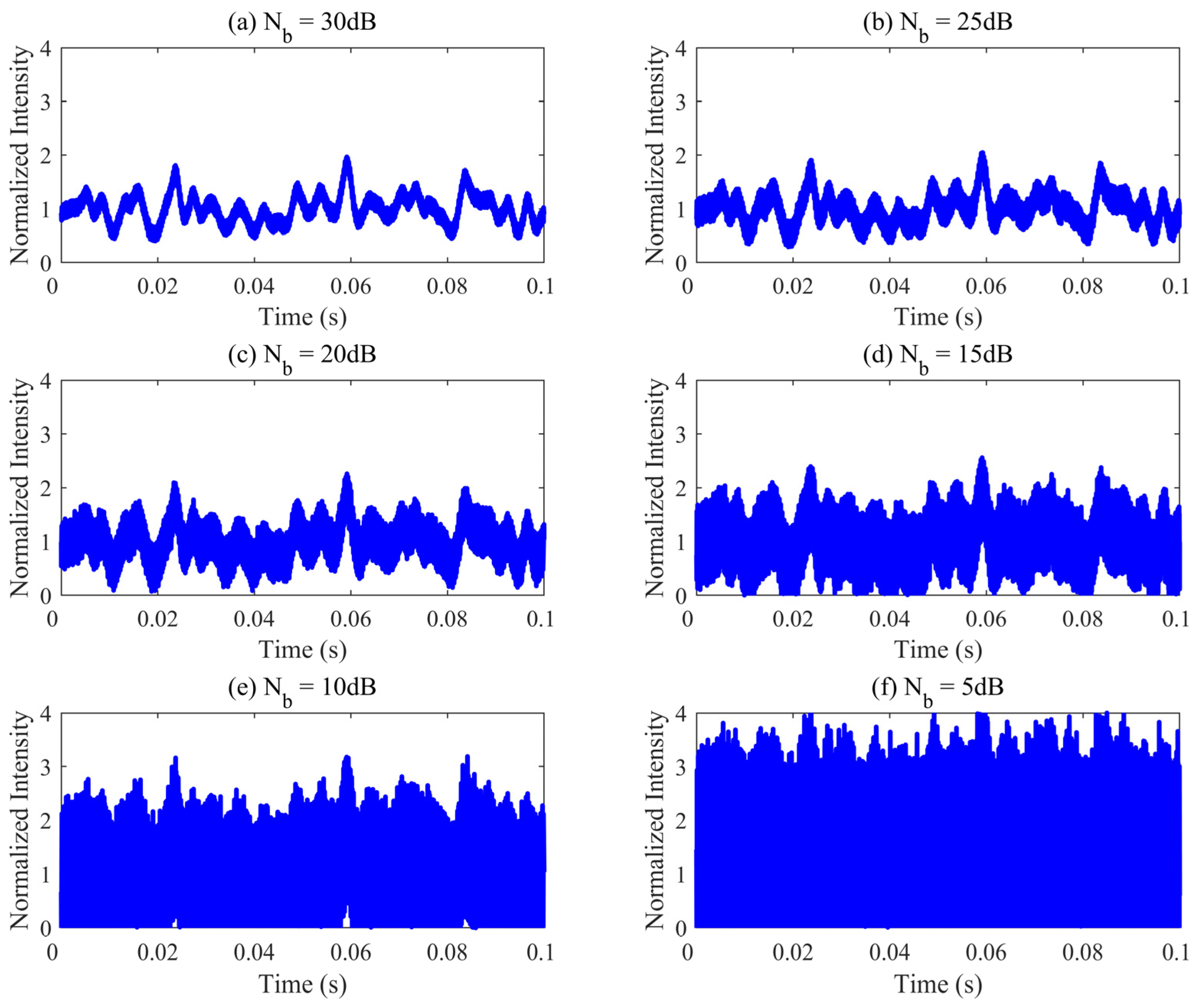
Figure 1. Schematic of bidirectional atmospheric channel model.
Photonics 10 01067 g001
Figure 2. Block diagram of adaptive power transfer system.
Photonics 10 01067 g002
Figure 3. (a) Performance of FTD in different turbulent channels. (b) Performance of ATD in different turbulent channels.
Photonics 10 01067 g003
Figure 4. Plot of the time-domain performance of the signal as it passes through different turbulent channels; σ 2 represents channel turbulence intensity. (a) OOK signal, (b) σ 2 = 0.0596 , (c) σ 2 = 0.0684 , (d) σ 2 = 0.1002 , (e) σ 2 = 0.1896 , (f) σ 2 = 0.3299 , (g) σ 2 = 0.5250 .
Photonics 10 01067 g004
Figure 5. Ideal BER performance of the three techniques in two channels with different turbulence strengths. (a) σ 2 = 0.0596 , (b) σ 2 = 0.5250 .
Photonics 10 01067 g005
Figure 6. Time-domain performance of a signal through the turbulent channel of σ 2 = 0.0596 with different background noises. (a) Nb = 30 dB, (b) Nb = 25 dB, (c) Nb = 20 dB, (d) Nb = 15 dB, (e) Nb = 10 dB, (f) Nb = 5 dB.
Photonics 10 01067 g006
Figure 7. BER performance of the three techniques in different turbulent channels when Nb = 30 dB. (a) σ 2 = 0.0596 , (b) σ 2 = 0.5250 .
Photonics 10 01067 g007
Figure 8. BER performance of the three techniques in different turbulent channels when Nb = 25 dB. (a) σ 2 = 0.0596 , (b) σ 2 = 0.5250 .
Photonics 10 01067 g008
Figure 9. BER performance of the three techniques in different turbulent channels when Nb = 20 dB. (a) σ 2 = 0.0596 , (b) σ 2 = 0.5250 .
Photonics 10 01067 g009
Figure 10. BER performance of the three techniques in different turbulent channels when Nb = 15 dB. (a) σ 2 = 0.0596 , (b) σ 2 = 0.5250 .
Photonics 10 01067 g010
Figure 11. BER performance of the three techniques in different turbulent channels when Nb = 10 dB. (a) σ 2 = 0.0596 , (b) σ 2 = 0.5250 .
Photonics 10 01067 g011
Figure 12. BER performance of the three techniques in different turbulent channels when Nb = 5 dB. (a) σ 2 = 0.0596 , (b) σ 2 = 0.5250 .
Photonics 10 01067 g012
Table 1. Three channel reciprocity measurements with different background noise added for two turbulent channels.
σ 2 N b ( dB ) ρ 1 ρ 2 ρ 3
0.0596300.99120.99120.9912
250.97300.97300.9730
200.92140.92150.9214
150.80000.80000.8001
100.59960.60000.5999
50.38860.38870.3882
0.5250300.99860.99860.9986
250.99540.99540.9954
200.98580.98580.9856
150.95700.95700.9570
100.88030.88020.8803
50.72200.72190.7219
ρ 1 , ρ 2 , and ρ 3 represent three channel reciprocity measurements. The ρ used within the article was the average of the three times.
Disclaimer/Publisher’s Note: The statements, opinions and data contained in all publications are solely those of the individual author(s) and contributor(s) and not of MDPI and/or the editor(s). MDPI and/or the editor(s) disclaim responsibility for any injury to people or property resulting from any ideas, methods, instructions or products referred to in the content.

