Photonic Generation of Background-Free Phase-Coded Microwave Pulses with Elimination of Power Fading

 ,
, 
Abstract
:1. Introduction
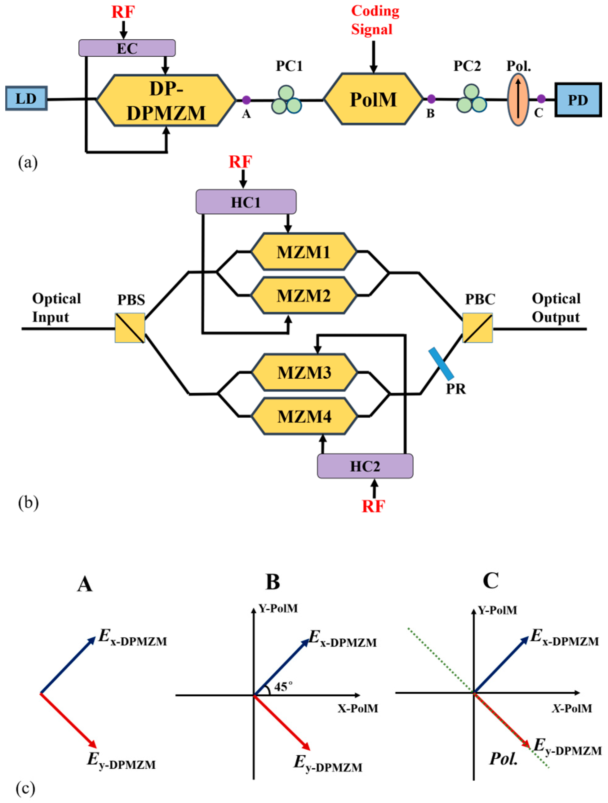
2. Principle and Methods
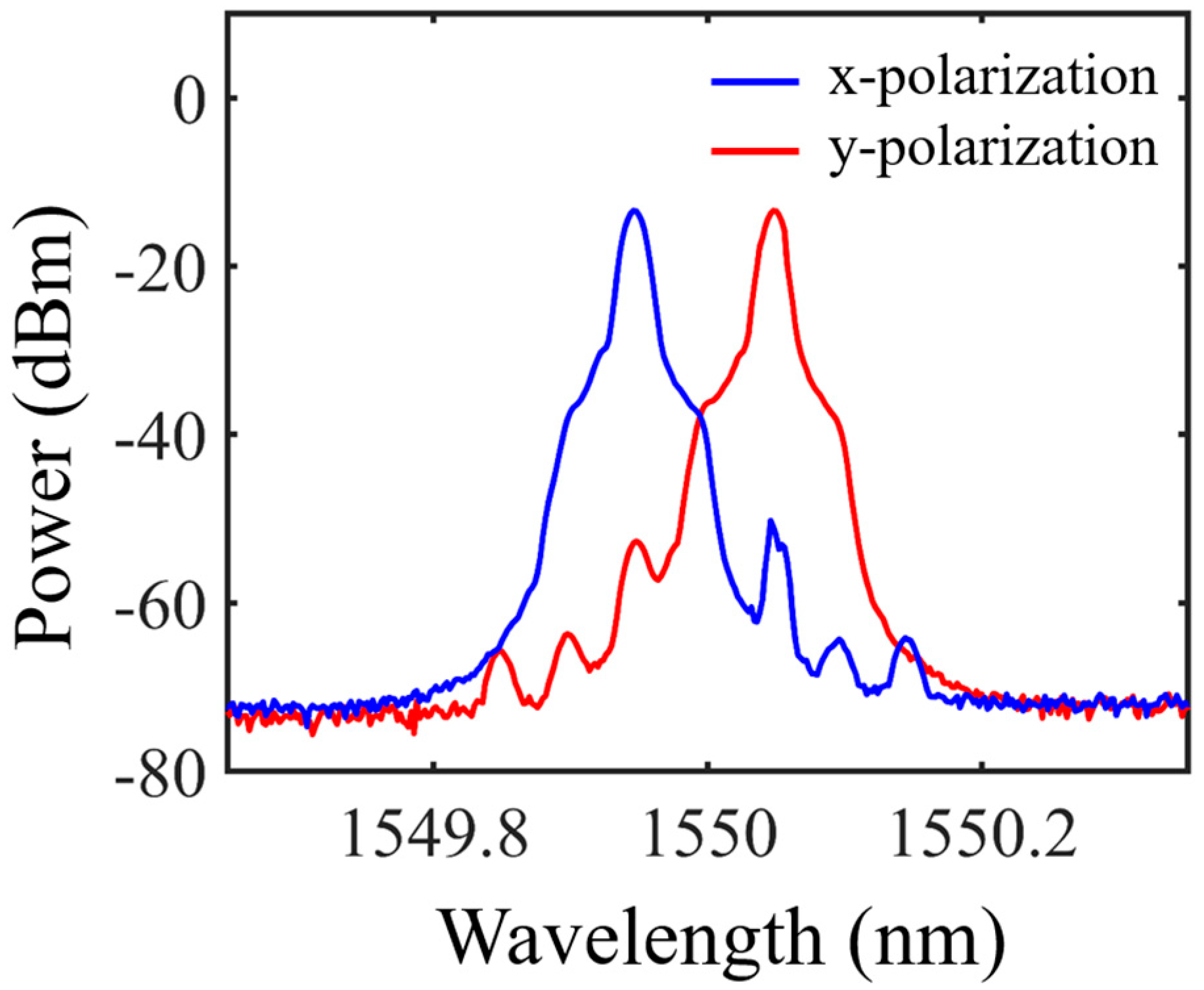
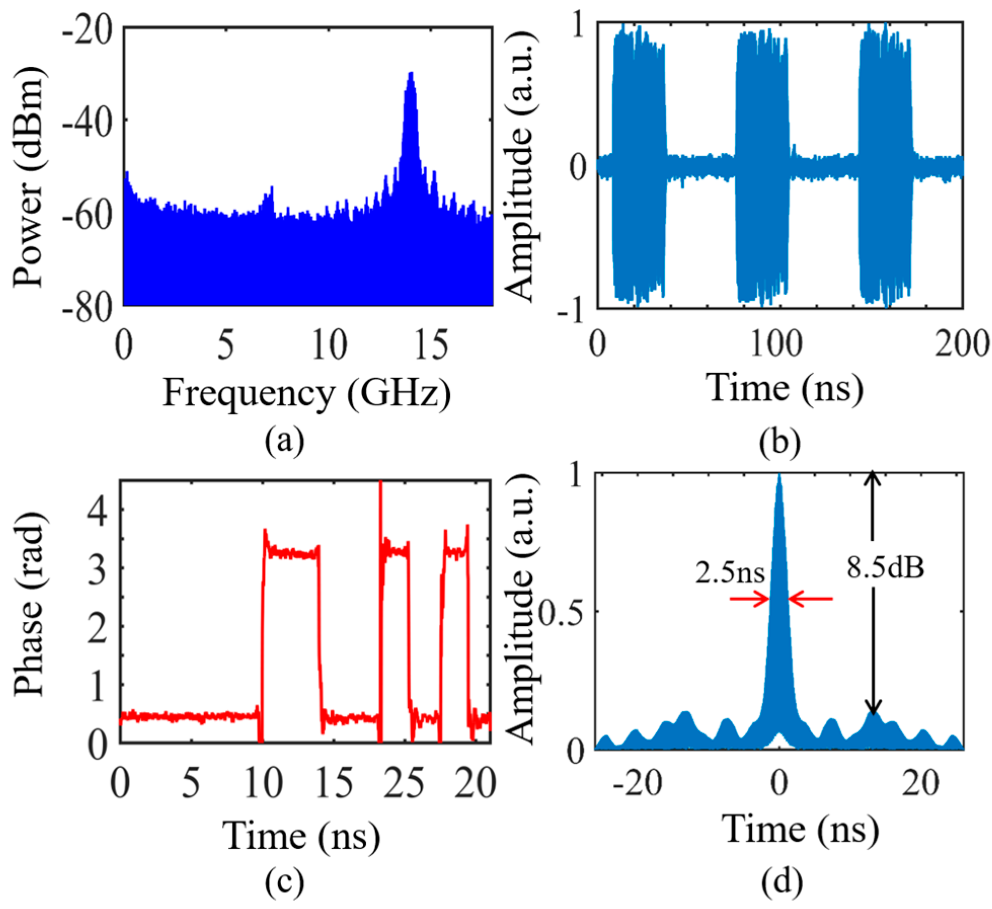
3. Results
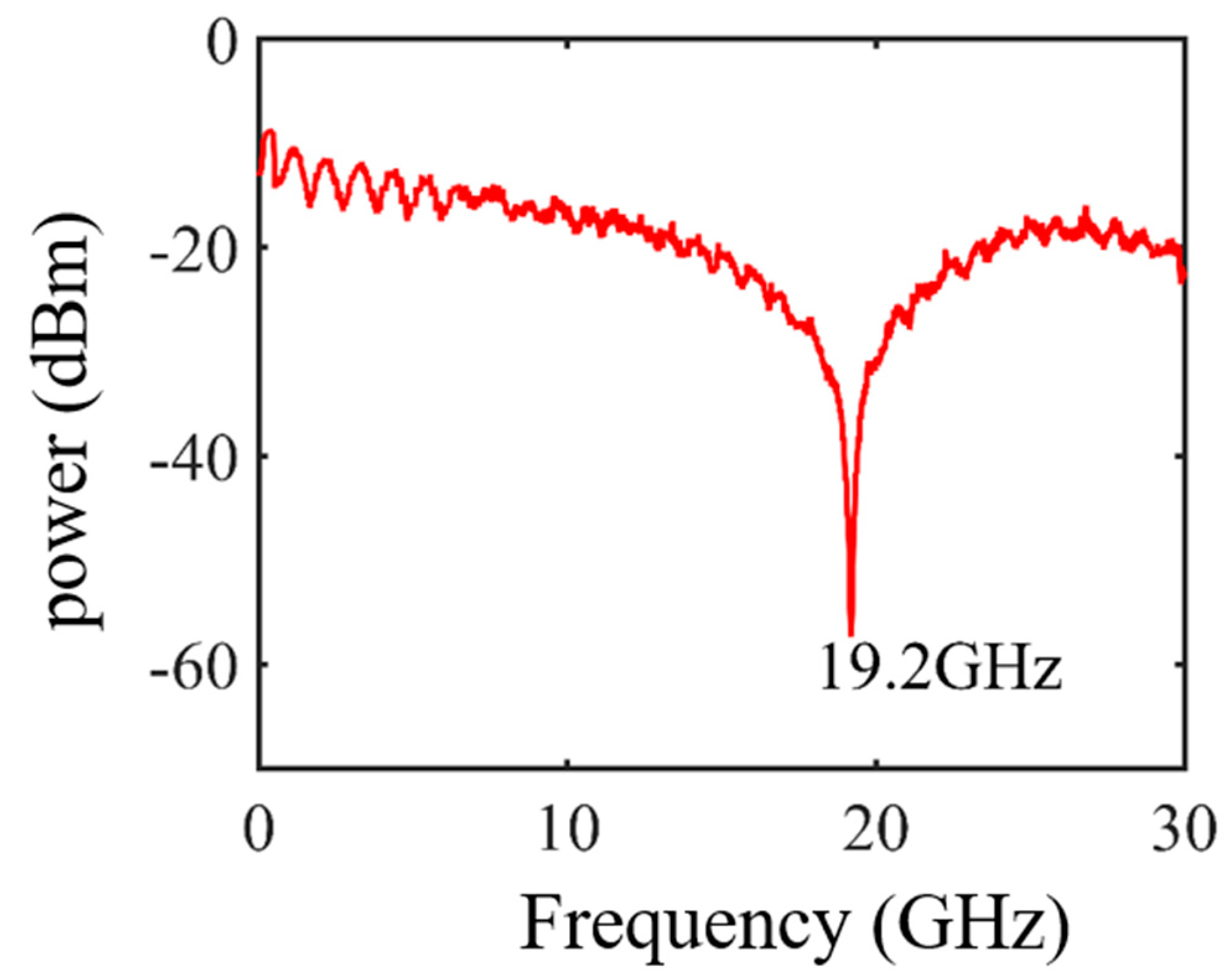
4. Discussion
5. Conclusions
Author Contributions
Funding
Institutional Review Board Statement
Informed Consent Statement
Data Availability Statement
Conflicts of Interest
References
- Skolnik, M. Role of radar in microwaves. IEEE Trans. Microw. Theory Tech. 2002, 50, 625–632. [Google Scholar] [CrossRef] [Green Version]
- Ghelfi, P.; Laghezza, F.; Scotti, F. A fully photonics-based coherent radar system. Nature 2014, 507, 341–345. [Google Scholar] [CrossRef]
- McKinney, J.D.; Leaird, D.E.; Weiner, A.M. Millimeter-wave arbitrary waveform generation with a direct space-to-time pulse shaper. Opt. Lett. 2002, 27, 1345–1347. [Google Scholar] [CrossRef] [PubMed]
- Ye, J.; Yan, L.; Chen, Z.; Pan, W.; Luo, B.; Zou, X.; Yi, A.; Yao, S. Photonic generation of microwave phase-coded signals based on frequency-to-time conversion. IEEE Photon. Technol. Lett. 2012, 24, 1527–1529. [Google Scholar] [CrossRef]
- Tang, Z.; Zhang, T.; Zhang, F.; Pan, S. Photonic generation of a phase-coded microwave signal based on a single dual-drive Mach–Zehnder modulator. Opt. Lett. 2013, 38, 5365–5368. [Google Scholar] [CrossRef] [PubMed]
- Li, W.; Wang, L.; Li, M.; Wang, H.; Zhu, N. Photonic generation of binary phase-Coded microwave signals with large frequency tunability using a Dual-Parallel Mach–Zehnder Modulator. IEEE Photon. J. 2013, 38, 5365–5368. [Google Scholar]
- Chen, Y.; Pan, S. A frequency-tunable binary phase-coded microwave signal generator with a tunable frequency multiplication factor. IEEE Photon. J. 2017, 9, 1–15. [Google Scholar] [CrossRef]
- Zhu, S.; Shi, Z.; Li, M.; Zhu, N.; Li, W. Simultaneous frequency up-conversion and phase coding of a radio-frequency signal for photonic radars. Opt. Lett. 2018, 43, 583–586. [Google Scholar] [CrossRef] [PubMed]
- Zhang, Y.; Zhang, F.; Pan, S. Generation of frequency-multiplied and phase-coded signal using an optical polarization division multiplexing modulator. IEEE Trans. Theory Tech. 2017, 65, 651–660. [Google Scholar] [CrossRef]
- Zhai, W.; Wen, A. Microwave photonic multifunctional phase coded signal generator. IEEE Photon. Technol. Lett. 2019, 31, 1377–1380. [Google Scholar] [CrossRef]
- Zhai, W.; Wen, A. Photonic generation of a dual-band polyphase-coded microwave signal with a tunable frequency multiplication factor. J. Light. Technol. 2019, 37, 4911–4920. [Google Scholar] [CrossRef]
- Chi, H.; Yao, J. An approach to photonic generation of high-frequency phase-coded RF pulses. IEEE Photon. Technol. Lett. 2007, 19, 768–770. [Google Scholar] [CrossRef]
- Chi, H.; Yao, J. Photonic Generation of Phase-Coded Millimeter-Wave Signal Using a Polarization Modulator. IEEE Microw. Wirel. Compon. Lett. 2008, 18, 371–373. [Google Scholar] [CrossRef]
- Fan, X.; Cao, X.; Li, M.; Zhu, N.; Li, W. Photonic Generation of Multi-Band Phase-Coded Microwave Pulses by Polarization Manipulation of Optical Signals. J. Light. Technol. 2021, 40, 672–680. [Google Scholar] [CrossRef]
- Li, W.; Wang, L.; Wang, H.; Zhu, N. Photonic generation of widely tunable and background-free binary phase-coded radio-frequency pulses. Opt. Lett. 2013, 38, 3441–3444. [Google Scholar] [CrossRef] [PubMed] [Green Version]
- Zhu, S.; Li, M.; Zhu, N.; Li, W. Transmission of dual-chirp microwave waveform over fiber with compensation of dispersion-induced power fading. Opt. Lett. 2018, 43, 2466–2469. [Google Scholar] [CrossRef] [PubMed]
- Wang, L.; Li, W.; Wang, H.; Zheng, J.; Liu, J.; Zhu, N. Photonic generation of phase coded microwave pulses using cascaded polarization modulators. IEEE Photon. Technol. Lett. 2013, 25, 678–681. [Google Scholar] [CrossRef]
- Yao, J.; Zeng, F.; Wang, Q. Photonic generation of ultrawideband signals. J. Light. Technol. 2007, 25, 3219–3235. [Google Scholar]


Disclaimer/Publisher’s Note: The statements, opinions and data contained in all publications are solely those of the individual author(s) and contributor(s) and not of MDPI and/or the editor(s). MDPI and/or the editor(s) disclaim responsibility for any injury to people or property resulting from any ideas, methods, instructions or products referred to in the content. |
© 2023 by the authors. Licensee MDPI, Basel, Switzerland. This article is an open access article distributed under the terms and conditions of the Creative Commons Attribution (CC BY) license (https://creativecommons.org/licenses/by/4.0/).
Share and Cite
Guan, M.; Wang, L.; Li, F.; Chen, X.; Li, M.; Zhu, N.; Li, W. Photonic Generation of Background-Free Phase-Coded Microwave Pulses with Elimination of Power Fading. Photonics 2023, 10, 66. https://doi.org/10.3390/photonics10010066
Guan M, Wang L, Li F, Chen X, Li M, Zhu N, Li W. Photonic Generation of Background-Free Phase-Coded Microwave Pulses with Elimination of Power Fading. Photonics. 2023; 10(1):66. https://doi.org/10.3390/photonics10010066
Chicago/Turabian StyleGuan, Mengyuan, Lu Wang, Fangping Li, Xiaoyu Chen, Ming Li, Ninghua Zhu, and Wei Li. 2023. "Photonic Generation of Background-Free Phase-Coded Microwave Pulses with Elimination of Power Fading" Photonics 10, no. 1: 66. https://doi.org/10.3390/photonics10010066