1. Introduction
Due to the flexibility and cost-effectiveness, unmanned aerial vehicles (UAVs) have become widely employed in a variety of applications for emergency communication, transportation, weather monitoring, and other domains [
1]. The use of UAVs for these applications is expected to grow dramatically in the coming decades in order to meet the ever-increasing requirements of the high-speed network between data servers (ground station) and UAVs in the atmosphere [
2]. It is promising to employ light’s orbital angular momentum (OAM) in air–ground laser communication networks, bringing in advantages such as lager channel capacity and higher spectral efficiency [
3,
4,
5,
6], since OAM, theoretically, has infinite eigenmodes and can form infinite-dimensional Hilbert space, which provides better candidates to realize multi-channel information transmission. Nevertheless, those so-called vortex beams naturally carrying OAM have not yet been effectively employed and developed in air–ground laser communication because of the turbulent effects during atmosphere transmission [
7,
8]. Atmosphere turbulence adversely affects the transmissions of vortex beam and its OAM, resulting in several deleterious turbulent phenomena such as OAM mode’s crosstalk [
9,
10,
11], OAM spectrum’s dispersion [
12,
13], vortex splitting [
14,
15,
16] and communication capacity reduction [
17,
18]. Seeking appropriate strategies to enhance the robustness of OAM to atmospheric turbulence during its propagation is an open challenge and common requirement for developing OAM communication technology [
19,
20]. Recently, a particular type of vortex beam named vector vortex beam (VVB) has attracted attention due to its seemingly inherent resistance to turbulence in terms of scintillation [
21], OAM spectrum [
22,
23] and intensity evolution behavior [
24]. VVB can guarantee that the characteristic hollow structure is more stable in turbulence than scalar vortex beam, and the OAM mode can be identified with a longer propagation distance. Moreover, VVB inherits the advantages of vector beams with non-homogenous polarization distribution and vortex beams with helical phase structure, and the coupling between SAM and OAM makes VVB a preferred option for optical manipulation [
25] and communication [
26]. Hence, it is of practical significance to investigate how the performance of the OAM communication system operated in the air–ground atmospheric turbulence channel can be enhanced by utilizing vector vortex beams.
Due to its distinctive channel characteristics, an accurate description of uplink and downlink air–ground atmosphere channels is of pivotal importance for characterization and performance analysis of air–ground communication systems between ground stations and UAVs for which the effects of continuously changing turbulence strength and structure need to be accounted for throughout the theoretical calculations [
8]. The Earth’s atmosphere consists of the atmospheric boundary layer and the free atmosphere according to the altitude. The large-scale turbulent eddies in the free atmosphere are firstly generated by solar radiation and possess inhomogeneous and anisotropic characteristics [
27,
28]. Large-scale turbulent eddies gradually break down into smaller turbulent eddies in the lower atmosphere under inertial forces, and the small-scale turbulent eddies in the atmospheric boundary layer are considered statistically homogeneous and isotropic [
29]. Consequently, in the information transfer process of air–ground communication between ground stations and UAVs, the data-carrying light beam experiences both isotropic and anisotropic turbulence with a variable anisotropic parameter (i.e., anisotropic parameter increases with altitude). Several slant air–ground atmospheric turbulence channel modes have been built based on the isotropic atmospheric turbulent spectrum [
30] or anisotropic one [
23,
31] alone, while few research studies have been conducted to integrate them. To cope with this issue, an attempt is made to incorporate isotropic and anisotropic atmospheric turbulent spectrums into modelling uplink and downlink air–ground atmosphere channels, and evaluate the performance of air–ground laser communication systems.
In this paper, based on the modified uplink and downlink atmosphere turbulent channel models, the turbulent effects on the transmission of OAM modes and OOK-modulated air–ground OAM communication system performance between ground stations and UAVs can be analyzed under various conditions. The multilayer phase screens method is employed for modeling the intensity evolutions of the vector and scalar vortex beams in the same turbulence, and the expected stabler intensity pattern of vector vortex beam is presented, indicating vector vortex beam provides a great alternative to the scalar one in the atmospheric channel. The signal OAM modes probability of vector vortex beam for uplink and downlink atmospheric turbulence transmissions are further examined, confirming its advantage. The performances of air–ground OAM communication system with Bessel–Gaussian (BG) and Laguerre–Gaussian (LG) beams are compared, indicating that BG beams are not appropriate for use in long-distance free-space links.
2. Theoretical Model
Figure 1 illustrates a conceptual diagram of the air–ground OAM communication system between ground stations and UAVs in the turbulent atmospheric channel. In the OAM information transfer process, data-carrying vector vortex beams travel in the complex atmospheric turbulence channel from optical ground station/UAV to UAV/optical ground station, and the atmospheric channel normally consists of the free atmosphere and the atmospheric boundary layer. The heights of UAV and ground station are represented as
H and
h0, respectively.
γ is the zenith angle and the total link distance is
z = (
H −
h0)/cos(
γ). To describe the difference in optical turbulence between the atmospheric boundary layer and the free atmosphere, the spatial power spectrum of the refractive-index fluctuations Φ
n(
κ,
h) in the atmosphere can be split into two parts,
where
H0 represents the critical position between the free atmosphere and the atmospheric boundary layer; here, we assume
H0 is fixed at 1 km (Other values can also be taken).
In free atmosphere (altitude above
H0), optical turbulence appears to be anisotropic, which needs to be described by the anisotropic non-Kolmogorov spatial power spectrum [
28],
where
α is the non-Kolmogorov power spectrum index with 3 <
α < 4;
,
ζx and
ζy = 1 + (
H −
H0)/
c0 are the effective anisotropy factors, balance parameter
c0 is assumed to be 2000,
A(
α) is given by
Here, symbol Γ(
x) is the Gamma function;
is a generalized structure parameter with units m
3−α and can be modeled by the Hufnagel-Valley (H-V) model [
8],
where
h is the altitude,
v is the root mean square (RMS) wind speed and
is the refractive index structure constant at sea level.
In the atmospheric boundary layer (altitude below
H0), it is assumed that the optical turbulence becomes homogeneous (i.e., statistically stationary) and isotropic under the influence of inertial forces. Anisotropic non-Kolmogorov spatial power spectrum reduces to the conventional isotropic non-Kolmogorov spectrum model by putting
ζx =
ζy = 1 in Equation (2)
For the transmission modeling problems of the vector vortex beam in atmospheric turbulence, the vector integration process needs to decompose the vector vortex beam into scalar vortex beams, and then calculate them separately. A vector vortex beam can be divided into two scalar vortex beams in the horizontal
x and vertical
y polarization directions, and each component is individual. Thus, the electric field of a cylindrically polarized vortex beam at the source plane (i.e.,
z = 0) can be decomposed as [
32]:
where
r = (
r,
φ) is the two-dimensional position vector at the source plane;
s0 is the OAM mode quantum number or topological charge;
φ is the azimuthal angle;
φ0 represents the initial phase angle, if
φ0 takes 0 and π/2, Equation (6) denotes the well-known radially and azimuthally polarized vortex beam, respectively. The radial function
represents the field variation along the radial coordinate, which can be used to distinguish the field type of vortex beams.
By making use of Euler’s Formula, both the electric fields of circularly polarized vortex beams after being decomposed to
x and
y polarization directions at the source plane can be expanded as,
The above expansions show that each component of a cylindrically polarized vortex beam in x and y polarization directions can be decomposed into a positive vortex encoded onto a right circularly polarized beam and a negative vortex encoded onto a left circularly polarized beam. The intensity patterns of the components in x and y polarization directions of a cylindrically polarized vortex beam with different OAM modes s0 break up into 2s0 light spots, and the phase patterns appear as the clockwise and counter-clockwise rotations with the corresponding angle φ0 on the intensity and phase diagrams of the x- and y-polarized components, respectively.
Based on the Huygens–Fresnel principle, the
x- and
y-polarized electric field components of a cylindrically polarized vortex beam in the free space without atmospheric turbulence and under the paraxial approximation can be expressed as
For BG beams and LG beams, each radial function can be expressed as [
33]:
where
ρ = (
ρ,
ϕ),
q = 1 + i
z/
z0, and
z0 =
kw02/2 is the Rayleigh range,
η =
ksin
θ0w0 is a shape parameter that determines the beam profile of BG beam,
k = 2π∕
λ is the wave number of the incident wavelength
λ,
θ0 is the angle of conical wave that forms the Bessel beam,
Jm(
x) is the Bessel function of the first kind with
m order,
is the spot size at the distance
z with the initial beam width
w0, and
is the associated Laguerre polynomial.
For the OAM communication link in the range of kilometers, the influence of turbulence on the polarization state of a vector vortex beam can be ignored [
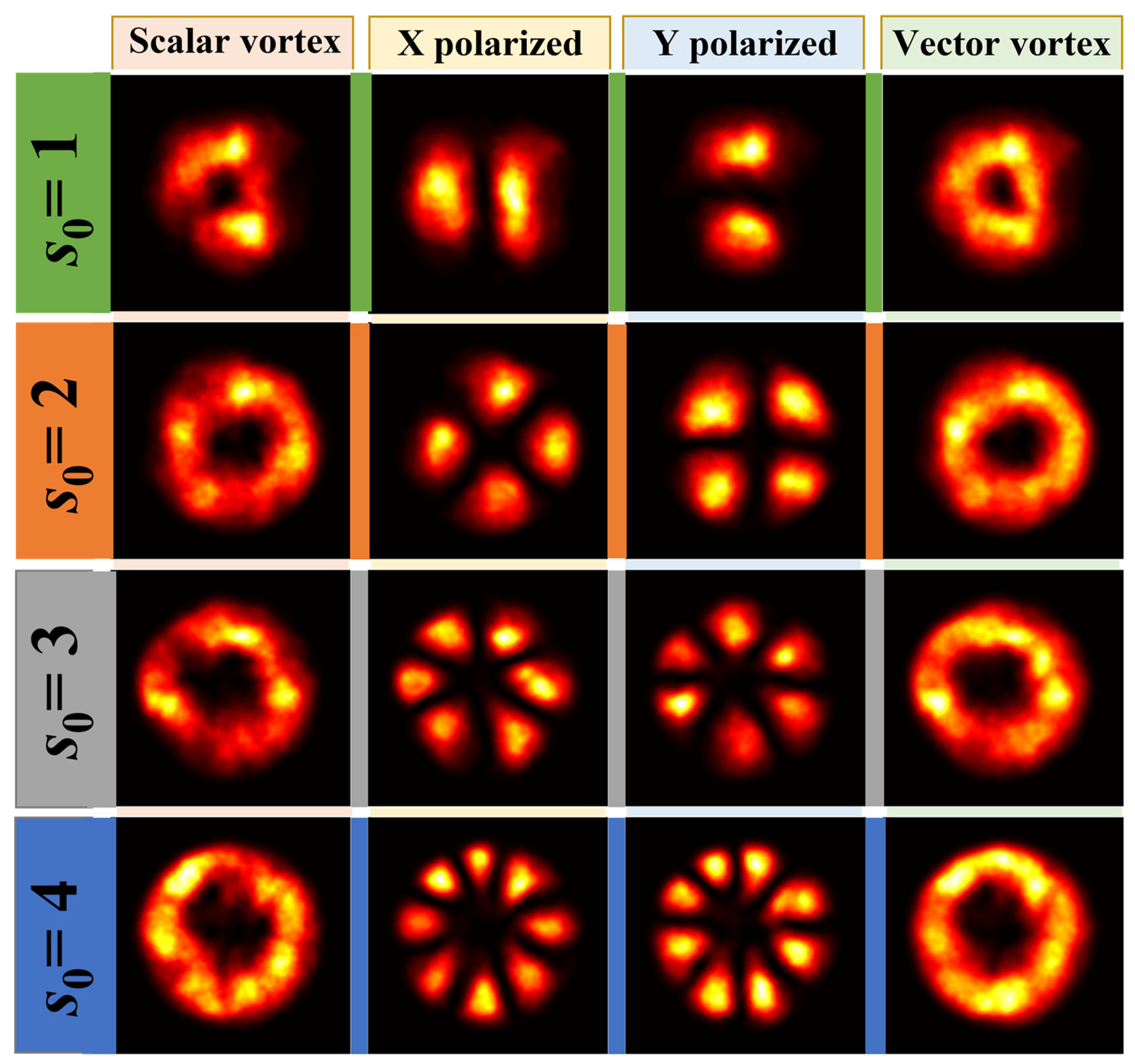
8]. The turbulence-induced phase distortion will occur obviously when a vector vortex beam propagates in an atmosphere channel. The intensity and phase diagrams of the components in
x and
y polarization directions of a cylindrically polarized vortex beam with different OAM mode
s0 and initial phase angle
φ0 after atmospheric turbulence propagation are simulated based on the multilayer phase screen method [
34] and presented in
Figure 2. Here, the turbulence simulation parameters are set as: propagation distance
z = 1.5 km, Fried parameter
r0 = 10 mm and 150 phase screens. With the increase in the OAM mode
s0, the effect of atmospheric turbulence on vortex beams is enlarged. However, the influence of the initial phase angle
φ0 can be ignored. Based on the independent propagation of
x- and
y-polarized components of a radially polarized vortex beam in atmospheric turbulence, the intensity patterns of radially polarized vortex beams with different OAM modes can be finally obtained. The comparison of intensity patterns between scalar and vector vortex beams (X-polarized component, Y-polarized component, and the ensemble) after propagation through the same atmospheric turbulence channel is displayed in
Figure 3. Compared to the scalar vortex beam, the vector vortex beam with the same OAM mode
s0 has a more uniform intensity (energy) distribution on the hollow beam structure, which means that the vector vortex beam can guarantee a circular dark hollow beam profile with a larger size and more stability in the atmosphere. Vector vortex beams can significantly improve the resistance to the turbulence on OAM modes carried by scalar vortex beams, which benefits air–ground OAM communication systems between ground stations and UAVs in an atmospheric turbulent channel [
24].
Similar to the treatment processing of scalar vortex beam propagation in the turbulence [
17], the cumulative effect of atmospheric turbulence on the transmission of a vector vortex beam can also be regarded as a pure phase disturbance based on the Rytov approximation method [
22,
23]. Under the condition of weak turbulence fluctuation, the
x-polarized electric field component of a cylindrically polarized vortex beam after atmospheric turbulence propagation can be given by:
where
Ψ1(
ρ,
z) is the complex phase perturbation of spherical waves in the turbulence.
Energy will be redistributed among various OAM modes when a vortex beam propagates in the turbulence, and several adjacent modes among the signal OAM mode will be detected at the receiver. Using the superposition theory of spiral harmonics [
35], Equation (14) can be rewritten as:
where the coefficient
is given by the integral,
OAM mode probability distribution density with quantum number
s can be expressed as
here, the asterisk denotes the complex conjugate.
The OAM mode probability with quantum number
s of cylindrically polarized vortex beams in the
x polarization direction after propagating in the turbulence can be expressed as
By substituting Equations (14) and (17) with Equation (18), we obtain
where the ensemble average term in the above formula takes the following form
where
and
ρ0 are the wave structure function and spatial coherence radius of spherical beam propagation through atmospheric turbulence [
8],
where
ξ denotes normalized distance variable, which is defined by
ξ = (
H −
h)/(
H −
h0) for the uplink path and by
ξ = (
h −
h0)/(
H −
h0) for the downlink path,
H =
h0 +
zcos(
γ) is the altitude of UAV platform,
h0 is the altitude of the ground platform and
γ is the zenith angle.
Substitute Equations (1), (2) and (5) with Equation (21) and employ second-order approximation (i.e.,
J0 (
x) ≈ 1 −
x2/4) [
36], the wave structure function of spherical wave propagation in the turbulent atmosphere can be derived,
where
.
The separation distance at which the modulus of the complex degree of coherence (DOC) falls to 1/e defines the spatial coherence radius
ρ0, i.e.,
. Based on the expressions given in Equation (22), we can obtain the spatial coherence length of spherical waves’ propagation in vertical atmospheric turbulence, which takes this form
Substituting Equations (9), (11)–(13) and (20) with (19) and using the orthogonality among OAM modes, integral over
ρ′, the detection probability of OAM mode
s in the
x polarization direction can be obtained as follows:
Based on the integral expressions [
37],
where
In(
x) is the modified Bessel functions of the first kind with
n order,
The normalized OAM mode probability of a cylindrically polarized vortex beam with signal OAM mode quantum number
s0 at the
z planeafter propagating in atmospheric turbulence by following relationship
Obviously, the mode probabilities of the OAM mode
s and −
s carried by a cylindrically polarized vortex beam in the
x and
y polarization directions are consistent,
Since the signal OAM mode
s0 of a cylindrically polarized vortex beam is decomposed into an equal quantum number of OAM modes with opposite signs ±
s0 during transmission, the OAM communication system based on the cylindrically polarized vortex beam needs to consider both the positive and negative OAM mode quantum numbers. To achieve this, the
x and
y polarization direction detectors are separately and independently employed to measure the opposite OAM quantum number, and identify them as the same positive OAM mode. Once the
x polarization direction detector receives OAM mode
s or the
y polarization direction detector receives the opposite OAM mode −s, in both two cases, it is assumed that the OAM mode
s is received. Thus, the detection probability of OAM mode
s carried by a cylindrically polarized vortex beam during atmospheric turbulence transmission is
where
m is an arbitrary OAM mod with a natural number.
To describe the channel loss and crosstalk of the OAM communication system, we introduce a signal-to-noise ratio (SNR) per bit, defined as the ratio between transmission power
PTX multiplied by the square of channel efficiency
P(
s0|
s0) and total noise power. Because each contributed crosstalk signal is modeled as an independent Gaussian source, the total noise power for a given channel is contributed by all OAM modal crosstalk powers,
P(
s|
s0), and the received total noise power,
N0, which is usually modeled by an additive Gaussian white noise, and the SNR can be written as [
9]:
If mode crosstalk
P(
s|
s0) (
s ≠
s0) is relatively small relative to channel loss
N0/
PTX (i.e., the transmission power is low), the OAM communication system will be limited by the detector noise. With the increase in transmission power,
N0/
PTX term in the denominator becomes small.
N0/
PTX can be ignored for a sufficiently large transmission power, and the OAM communication system is only limited by channel crosstalk. Similar with average capacity, average bit error rate (BER) is another important parameter to measure the performance of communication systems. BER is a measure of the accuracy of data transmission within a specified time, and the average BER of the OOK-modulated OAM communication system in the turbulent atmosphere can be expressed as
3. Simulation Results and Discussion
In this section, to investigate the link performance of the air–ground OAM communication system utilizing vector vortex beams in atmospheric turbulence, the OAM mode detection, OAM spectrum, and the average BER are examined, and the simulation parameters are summarized in
Table 1, unless otherwise specified.
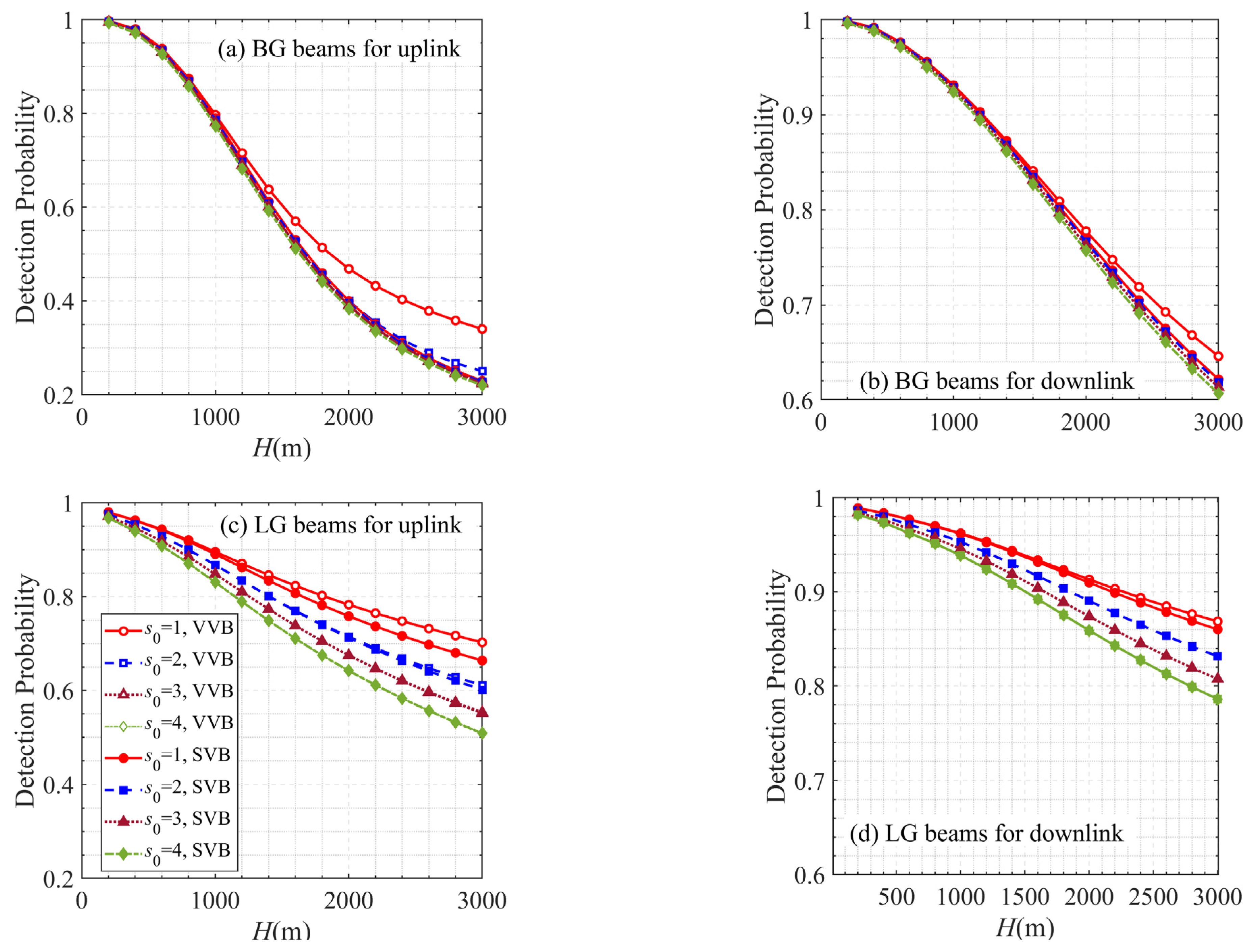
The impacts of topological charges
s0 on the signal mode detection probability of vector and scalar vortex beams for both uplink (a, c) and downlink (b, d) atmospheric turbulence transmissions are illustrated by changing the topological charges (i.e.,
s0 = 1, 2, 3, and 4), as shown in
Figure 4. The comparisons of BG and LG beams are depicted in
Figure 4a,b and
Figure 4c,d, respectively. The labels of the change curves are shown in
Figure 4c. As expected, the signal mode detection probability of vector and scalar vortex beams in the turbulent atmosphere decrease with the increases of topological charges and the height of UAV (i.e., link distance) as the turbulence effect intensifies. Compared to the downlink atmosphere transmission, turbulence in the uplink atmosphere channel has a much stronger influence on the transmission of OAM modes because the vortex beam experiences much stronger turbulence at the initial transmission stage in the uplink atmosphere channel. The vector vortex beam performs better on transmitting the signal OAM mode in the atmospheric turbulence than in the corresponding scalar vortex beams, especially when the topological load is small. Additionally, the advantages become slightly more apparent with an increase in the turbulent strength. It is reasonable since the signal OAM mode carried by a vector vortex beam can be regarded as the superimposed OAM modes of opposite signs ±
s0 in the same proportion, and the atmospheric turbulence effects on the transmission of the signal OAM mode can be effectively reduced due to the reciprocal features of the OAM mode crosstalk [
38]. Considering the reciprocal features, the C-point vector vortex beams (superposition of the
s0 = 0 and
s0 OAM modes) seem to be superior to the V-point vector vortex beams (superposition of the ±
s0 OAM modes) [
34].
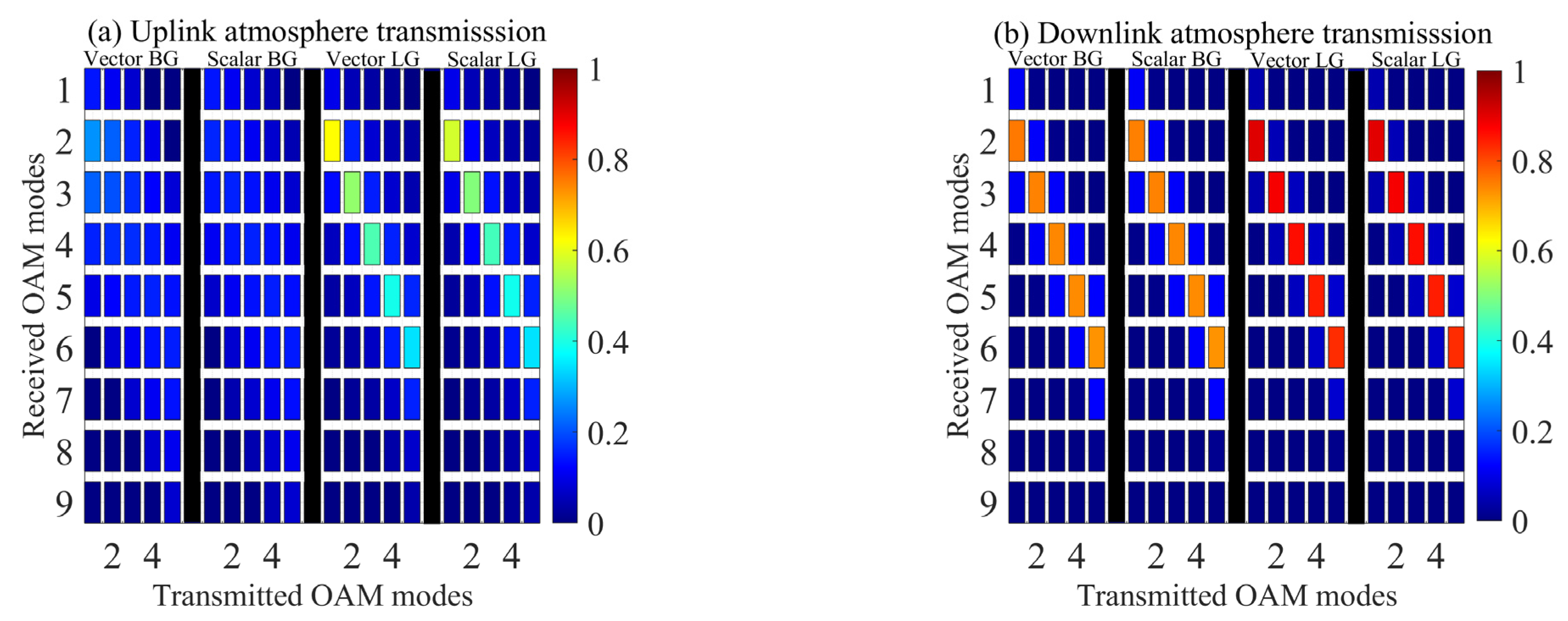
Figure 5 shows the OAM spectrum of vector and scalar vortex beams for uplink (a) and downlink (b) atmospheric turbulence transmissions. To achieve this, the signal OAM mode
s0 of BG and LG beams is changed from one to five. Compared to the downlink atmosphere transmission, turbulence, significantly, produced OAM mode crosstalk and the spread of the OAM spectrum of vortex beam for uplink atmosphere transmission, due to the stronger atmospheric turbulence. Adopting a vector vortex beam can effectively enhance the transmission quality of the signal OAM mode. However, typical BG beams cannot satisfy the long-distance uplink OAM communication requirements, and the easily modulated LG beams are more suitable for long-distance transmission with strong atmospheric turbulence. In downlink atmosphere transmission, the majority of OAM crosstalk appears with the neighboring modes (Δ
s = 1) and the other OAM modes crosstalk effect can be ignored.
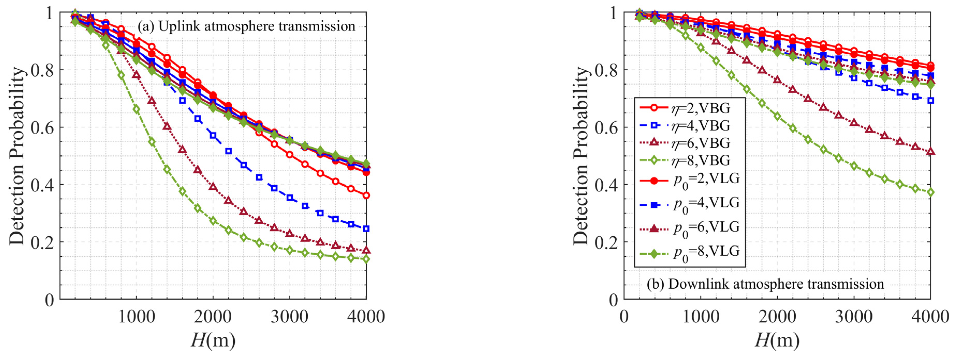
Figure 6 exhibits the signal OAM mode detection probability of vector vortex beams along the link distance (height of UAV) in both uplink and downlink atmosphere transmissions, where the effects of the beam shape parameter of the BG beam
η = 2, 4, 6, 8 and OAM radial mode of LG beams
p0 = 2, 4, 6, 8 are considered. For a short-distance atmosphere transmission, the signal OAM mode detection probability of vector vortex beams decreases with the decrease of the beam shape value
η and the increase in radial mode
p0; the performance of the BG beam is better than the LG beam. As the link distance increases, the dependences of signal OAM detection probability on
η and
p0 have a reversion after entering into a long-distance atmosphere transmission regime. The strength of turbulence determines the location of this reversal, and the location in downlink atmosphere transmission is farther than that in uplink atmosphere transmission. It can be concluded that BG beam is suitable for short-distance applications and LG beam is suitable for long-distance applications, which is further verified [
30].
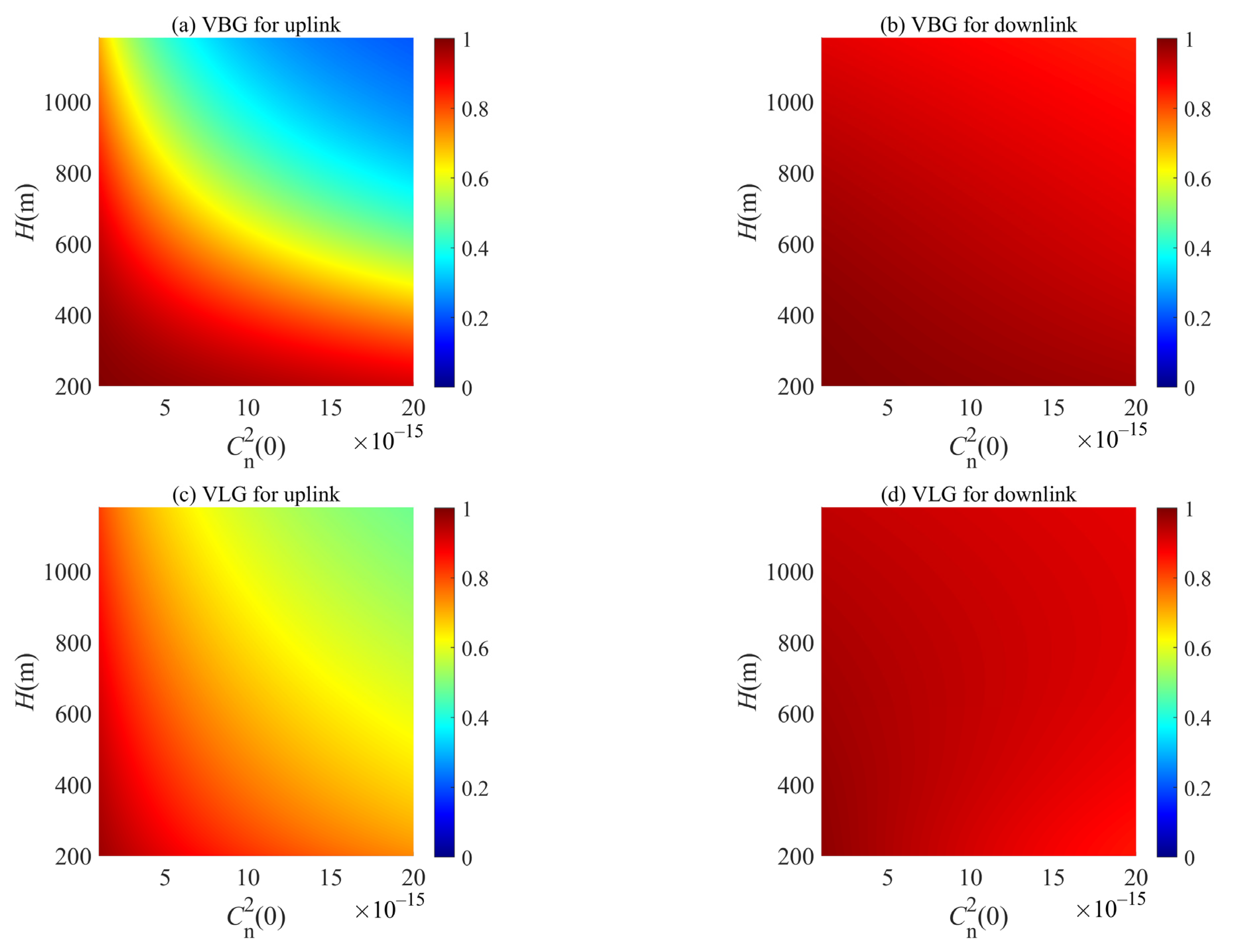
Figure 7 reveals the behavior of the signal OAM mode detection probability of vector BG and LG beams along the link distance (height of UAV) and refractive index structure constant (
) in both uplink (a, c) and downlink (b, d) atmosphere transmissions. The vortex beam transmitted in the downlink atmosphere channel performs better than in the uplink atmosphere channel. With the increase in the
and
H, atmospheric turbulence strengthens, and the signal OAM mode detection probability decreases. Noted that for the vector LG beam transmitted in the downlink atmosphere channel, the dynamic curves of signal OAM mode detection probability against the UAV height show a trend of increasing first and then decreasing. As the turbulence in the upper atmosphere is weaker, atmospheric turbulence strengthens during the transmission process of the laser beam in the downlink atmospheric channel. However, beam size will increase due to the free space diffraction effect, and the laser beam with the larger beam size has stronger resistance to turbulence disturbance, these two factors result in the optimal link height (height of UAV), when other parameters are determined.
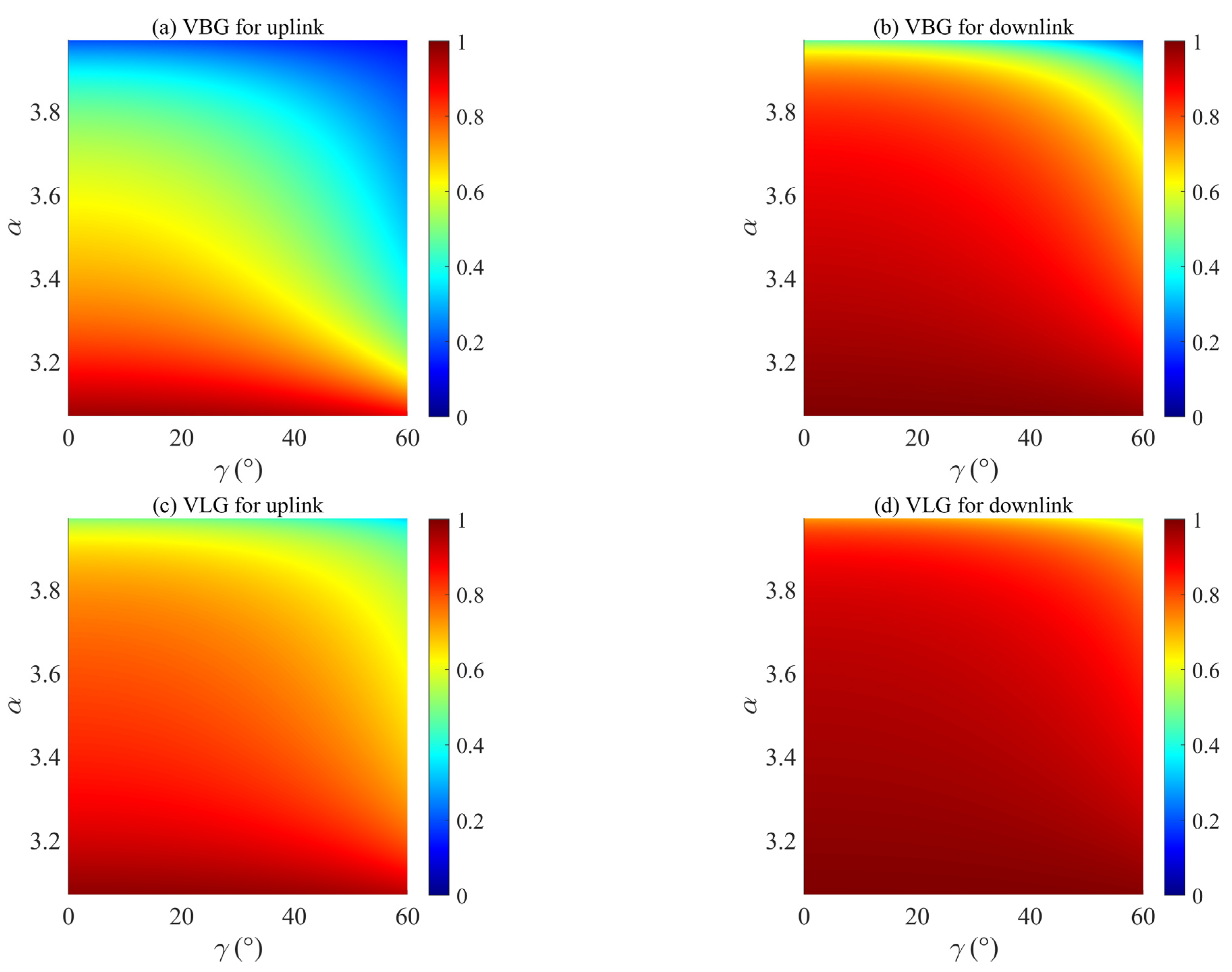
Figure 8 details the evaluation of the signal OAM mode detection probability of vector BG and LG beams along the power spectrum index
α and zenith angle
γ in both uplink (a, c) and downlink (b, d) atmosphere transmissions. It is clear that the larger zenith angle
γ results in a longer link distance for the same height of UAV, and atmospheric turbulence has a larger effect on the transmission of the OAM mode. Increasing the value of
α from 3.07 to 3.97, the downward trends of the signal OAM mode detection probability for uplink and downlink atmosphere transmission channels are different. For uplink atmosphere transmission, only when
α is less than 3.37, the vector vortex beam has a high signal OAM mode detection probability. However, for downlink atmosphere transmission, the main decline of signal OAM mode against
α occurs in the range of [3.87, 3.97].
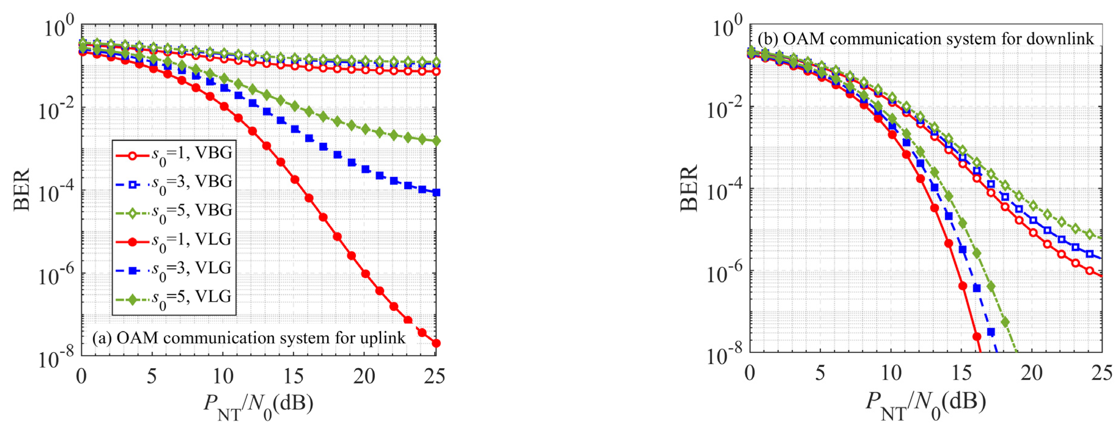
Now, we further evaluate the average BER of OOK-modulated air–ground OAM communication systems between ground stations and UAVs with a different signal OAM mode
s0 as a function of the ratio of power to noise
PNT/
N0 for uplink and downlink atmosphere channels in
Figure 9. Here, the signal OAM modes of vector BG and vector LG beams are selected as one, three, and five. The average BER of the air–ground OAM communication system increases with the increase in the signal OAM mode
s0 and the decrease in the ratio of power to noise
PNT/
N0. Atmospheric turbulence affects the transmission of OAM mode more, with a larger topological charge
s0, resulting in a higher average BER, especially in the uplink atmosphere channel. For long-distance uplink and downlink atmosphere channels, an OAM communication system based on the vector LG beam is superior to that based on the vector BG beam. It is proposed that increasing
PNT/
N0 is the proper way to improve the performance of OOK-modulated air–ground OAM communication systems, except for the vector BG beam for the uplink OAM communication.
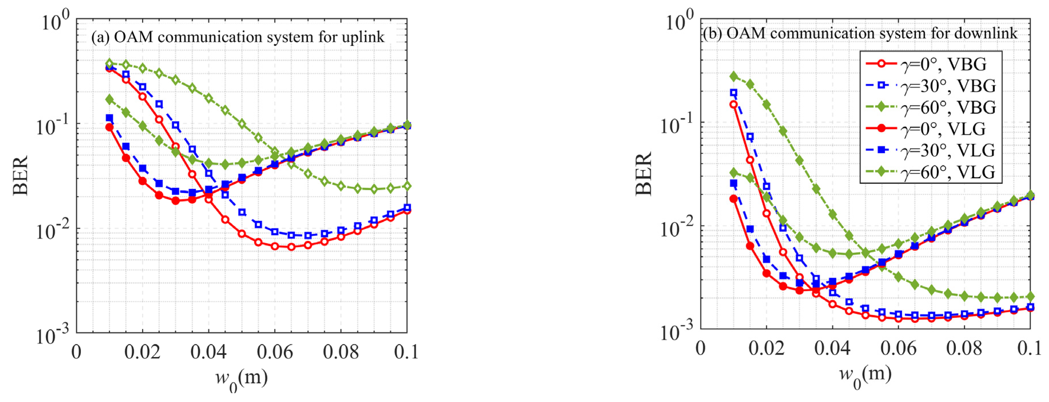
The influences of beam width
w0 and zenith angle
γ on the average BER of OOK-modulated air–ground OAM communication systems between ground stations and UAVs for uplink and downlink atmosphere channels are depicted in
Figure 10. Average BER decreases in the initial increasing phase of beam width
w0; zenith angle
γ shows obvious effects on the air–ground OAM communication system. When the beam width
w0 further increases, the average BER instead begins to increase, and the effect of the zenith angle
γ then gradually subsides. The result reflects that the beam width
w0 exists as an optimum value for air–ground OAM communication after the beam source and link model are determined.
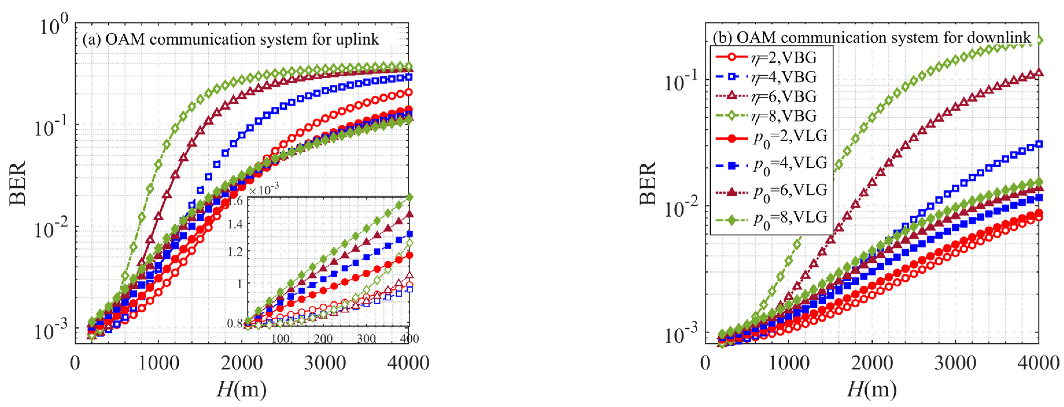
Figure 11 presents the average BER of OOK-modulated air–ground OAM communication systems between ground stations and UAVs for uplink and downlink atmosphere channels as a function of link distance (height of UAV)
H, where the effects of the beam shape parameter of BG beam
η = 2, 4, 6, 8 and radial mode of LG beams
p0 = 2, 4, 6, 8 are considered. The average BER of the air–ground OAM communication system increases with the increasing link distance due to more substantial atmospheric turbulence, and gradually enters the saturation state. Consistent with the results in
Figure 6, the vector BG beam with a larger beam shape parameter
η has the strong capability of turbulence disturbance rejection, the air–ground OAM communication system has a lower average BER. With the increase in link distance, the result is reversed, the air–ground OAM communication system based on the vector LG beam with a larger radial mode
p0 has a better performance in long-distance atmosphere channel.

 ,
, 


