Article

Numerical Simulation and Experimental Study of a Multistage Multiphase Separation System

1
Sichuan Changning Natural Gas Development Co., Ltd., Yibin 610051, China
2
Shale Gas Research Institute of PetroChina Southwest Oil & Gasfield Company, Chengdu 610051, China
3
School of Petroleum Engineering, China University of Petroleum (East China), Qingdao 266580, China
*
Author to whom correspondence should be addressed.
Separations 2022, 9(12), 405; https://doi.org/10.3390/separations9120405
Submission received: 20 October 2022 / Revised: 17 November 2022 / Accepted: 24 November 2022 / Published: 1 December 2022
(This article belongs to the Topic Oil, Gas and Water Separation Research)

Abstract

:
Nowadays, most oilfields have entered the high water cut stage of waterflood development. The importance of oil–water separation technology becomes more obvious. Gravity separation is one of the most commonly used treatment techniques for produced fluid. The gravitational separator has a large processing capacity and a wide application range, but its structure is relatively simple and the separation efficiency gradually falls behind to meet current production needs. The key difficulties to improve the separation efficiency are to analyze the flow field and coalescing components inside the separator. Aiming at these difficulties, this paper reports an innovatively designed series-parallel multistage multiphase separation system (MMSS). A horizontal separator is connected in series with a vertical separator, and the vertical separator consists of five discrete pipes connected in parallel. Different coalescing components are then set inside the vertical separator. The separation effect of the MMSS is studied by numerical simulation and laboratory experiments. The oil phase volume distribution cloud diagrams of coalescing components are analyzed by numerical simulation, including semicircle baffle, spiral track plate, four-hole plate and seven-hole plate. Laboratory experiments show that MMSS has a high separation efficiency, and the water content at the oil outlet is 3.0% less than that of the horizontal separator. By observing the shape of oil droplets at the outlet and measuring the oil cut and water cut at the sampling outlet, the separation effect of four coalescent plates is obtained. According to the statistics, when the volumetric flow at the inlet of the separator is 1.5 m3/h, the average particle size of oil drops in the blank pipe, semicircular baffle, four-hole plate, spiral track and seven-hole plate increases in turn. A continuous oil layer appears at the outlet of the vertical separator in the fully open state. The water content at the oil outlet of the semicircular baffle coalescing component is always at a high level under different flow rates. When the inlet volumetric flow rate is less than 1.6 m3/h, the performance of the spiral track coalescing component is better. With the increase of the inlet volumetric flow rate, the separation efficiency of the spiral track is lower than that of the orifice. The results show that the semicircular coalescing component has the worst performance, the spiral track coalescing component is superior at small volumetric flow rates, and the orifice coalescing component is superior at large volumetric flow rates.

Graphical Abstract

1. Introduction

With the continuous development of oil fields, most the oil fields in China have already entered the high water cut stage, and the production starts to decrease progressively. The separator is a key device for processing produced fluids and successfully extracting oil and gas, and how to effectively improve the separation efficiency is an important research focus. At present, common separation methods in the literature include gravity separation, centrifugal separation, coalescence separation, air flotation separation, filtration separation, etc. [1,2,3]. Gravity separation is the most important and widely used method for oily wastewater treatment, utilizing the differences in the density of oil and water for sedimentation and separation [4,5,6,7,8]. Wang et al. [9] used a gravity separation simulation test system to study the separation characteristics and flow laws of the horizontal separator. Results show that there is an optimal oil–water interface position in the separator to achieve the best separation effect. Acharya et al. [10] conducted computational fluid dynamics simulations on gravity separators with different water contents, and the results suggest that the separation efficiency of separators increases with the increase of water content. Ye et al. [11] carried out numerical simulation to optimize the efficiency of the separator. Based on this, a two-stage gas–liquid separator with a better separation effect and suitability for the actual well conditions was designed. Centrifugal separation is a method to separate oil and water by centrifugal force [12,13,14,15]. Zeng et al. [16] numerically simulated the internal flow field of the double-cone cyclone separator. The simulation results indicated that the center of the cyclone was an effective separation area, which laid a foundation for further research on the mechanism and structural optimization design of hydrocyclone. Zhang et al. [17] discussed the influence of the structural parameters of the cyclone separator on the separation performance by combining experiments and numerical simulation. The research suggests that the overflow port diameter of the separator has the greatest impact on the system efficiency. Further, de Luna et al. [18] simulated the flow field inside the cyclone separator and obtained the conclusion that pressure and tangential velocity are symmetrically distributed in the device. Coalescence separation corresponds to the different affinity between each phase in the oil–water mixture and the coalescing element [19,20,21,22]. Researchers have performed a significant amount of experimental research on the influence on coalescence separation performance, such as coalescence material selection, coalescence structure, operating conditions, emulsion properties [23,24,25]. Zhang et al. [26] optimized the shape and internal structure of the separator, and selected four coalescing elements with an angle of 120° for comparative experiments. The results show that the coalescing effect of a stainless-steel corrugated sheet is better than that of a polyethylene corrugated sheet. Pan et al. [27] established a numerical simulation and orthogonal experiment to investigate the influence and mechanism of flow rate, oil droplet size and surface wettability on the oil–water separation effect of the coalescing plate, whereby the flow rate has the greatest influence on the separation effect. Huang et al. [28] studied the coalescing behavior and mechanism of oil droplets in the dispersed phases. The results showed that, within a certain range, increasing the effective coalescing area or decreasing the plate inclination angle would improve the separation efficiency. In addition, the air flotation accelerates the floating speed of oil droplets by forming tiny bubbles in the oil–water mixture [29,30,31,32,33,34]. Filtration separates oil from water by using porous filter elements that allow the water phase to pass but prevent the oil phase from passing. The commonly used filtration methods include membrane filtration [35,36], fiber filtration [37,38], staged filtration, etc.
Although great advances have been made in the design of separators, there are limited significant structural innovations. Restricted by the structure of the original separator, most of them are only improved on the original basis. Many researchers have studied the internal flow field of the separator by numerical simulation. The conclusions obtained provide guiding significance to the design of the separator and a reference for the further study of the separation performance. The most widely used separation system is the combined horizontal separator. It is based on the addition of a variety of components to the traditional horizontal separator, such as coalescing components, rectifying components and entrance pendants.
In this paper, the mechanism of the coalescing separator is analyzed according to the gravity separation mechanism, equal flow theory and shallow pool theory. The horizontal separator and the vertical separator with different coalescing components are innovatively designed and connected to form a series-parallel multistage multiphase separation system (MMSS). The flow field inside the vertical separator was studied by Fluent. On the one hand, the effects of the parallel vertical separator, coalescing components and the flow rate on the system separation efficiency were studied by laboratory experiments. The results show that the separation efficiency of the MMSS is significantly improved compared with the single-stage horizontal separator. Four kinds of coalescing components, including spiral track, semicircular baffle, four-hole plate and seven-hole plate, have different promoting effects on oil–water separation of emulsions. The spiral track is more suitable for small flow separation, and the orifice plate component performs well in large flow separation.

2. Methods and Theories

2.1. Coagulation and Separation Mechanism

The produced fluid is an oil-in-water emulsion with an extremely high water cut. Due to the difference in oil and water density, the oil droplets in the dispersed phase moved upward by buoyancy. The speed of movement can be expressed by Stokes’ formula [39]:
v u p = ( ρ w ρ o ) g d o 2 18 μ
where ρw is the density of water; ρo is the density of oil; g is local gravitational acceleration; νup is the rising rate of oil droplets; μ is the viscosity of water; and do is the oil droplet size.
The oil droplets with smaller particle size continuously undergo Brownian motion [40]. After collision coalescence, the particle size becomes larger and the speed increases, which accelerates the process of oil and water separation. After coalescing oil droplets with particle sizes of d1, d2dn, the velocity is:
v l n = ( ρ w ρ o ) g ( d 1 5 + i = 2 n d i 5 ) 18 μ ( d 1 3 + i = 2 n d i 3 )
where νln is the rising rate of coalescent oil droplets; d is the oil droplet size; subscript 1 refers to the first oil droplet; and di represents the ith oil droplet.
Qi et al. [41] analyzed the coalescence process and the hydrodynamic characteristics of the droplet and the membrane. According to Navier–Stokes equation, the coalescence time model of the single droplet on the membrane is established. The formula points out that the coalescence time is related to the physical properties of the liquid, the area of the oil membrane, the size and velocity of the droplets, etc. In this study, the coalescence component in the discrete pipe can increase the area of the oil membrane by increasing the contact area with oil droplets. This can reduce the coalescence time and improve the separation efficiency. The flow rate of the droplets depends on the inlet flow rate, which can be controlled by adjusting the inlet flow rate. The coalescence time model of the single droplet on the membrane is established as follows:
t c = r f 2 u r + u c δ ln h 0 2 / u r + u c δ r f + σ h 0 2 3 R μ c r f 2 / h c 2 / u r + u c δ r f + σ h c 2 3 R μ c r f 2
where tc is the coalescence time of the droplet and the oil film, s; rf is the radius of the droplet and membrane deformation zone, m; ur and u are velocities of the interlayer drainage and membrane surface, respectively, m/s; h0 is the interlayer thickness of the initial liquid, m; hc is the critical liquid interlayer thickness, m; σ is the surface tension of the dispersed phase, N/m; μc is the viscosity of continuous phase, Pa s; and R is the deformation curvature radius of the droplet, m.

2.2. Isoflow Theory

The parallel design of the vertical separator satisfies the isoflow theory [42]. After the emulsion flows into the pipes, the descending speed meets the following formula:
v d o w n = 1 n Q A P = Q n A P
where Ap is the cross-section of pipes; Q is the inlet flow; and n is the number of pipes. When the flow rate is fixed, increasing the value of n can reduce νdown. Furthermore, the oil–water separation capacity of the separator is improved.

2.3. Shallow Pool Theory

In 1904, Hazen proposed the shallow pool theory [43]. Assuming that the pool length is L, the pool depth is H, the liquid velocity in the pool is ν, and the settling velocity of particles is μ0, the motion of droplets in the separator satisfies the formula L/H = ν/μ0. In the process of gravity separation, the separation effect of dispersed phase droplets is a function related to the droplet rate and the shallow pool area. Specifically, the efficiency of the separator can be improved by expanding the sedimentation area or increasing the settling speed.

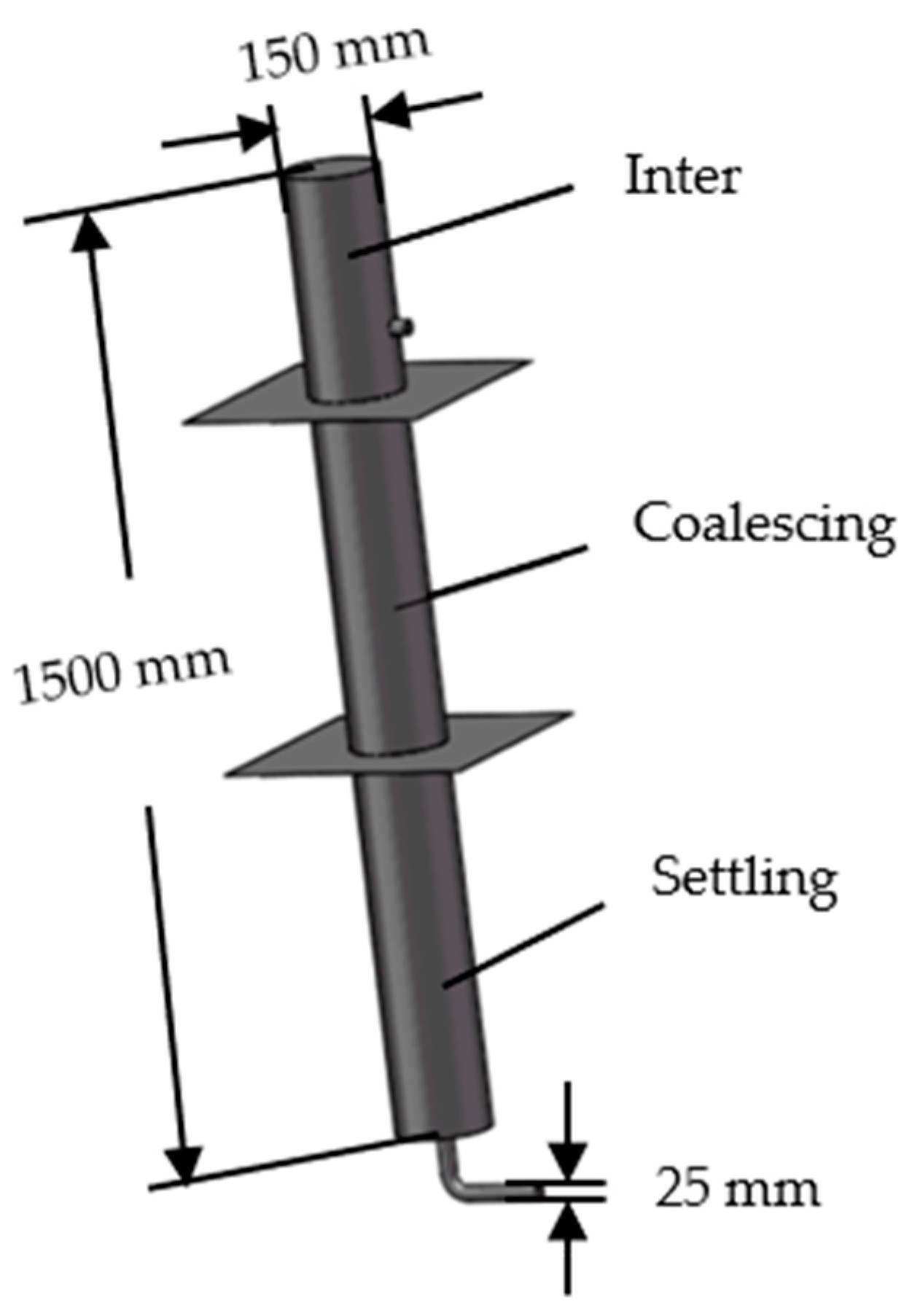
3. Multistage Multiphase Oil–Water Separation System

Gravity separators utilize the difference in gravity between oil, gas and water to separate them. It is the most widely used process equipment in the petroleum extraction and processing industry. According to the shape of the gravity separator, it can be divided into vertical and horizontal. The multistage multiphase oil–water separation system is shown in Figure 1. It is composed of a parallel vertical separator with a coalescing component and a horizontal separator connected in series. It combines the characteristics of horizontal and vertical separators, which has the advantages of a compact structure, insensitivity to liquid level fluctuation, large processing flow, high separation efficiency and large operation elasticity.
The parallel vertical separator is shown in Figure 2, which is designed based on the gravity separation and coalescence mechanism, isoflow flow and shallow pool theory. The main structure of the separator is the parallel connection between the central pipe and the five pipes, in which the four pipes are equipped with the spiral track, semicircular baffles, four-hole plates and seven-hole plates, respectively, and a blank pipe is left for a comparison experiment. The five risers are provided with an independent switch, which is summarized into a liquid inlet at the upper part of the separator and a liquid discharge port at the bottom.

4. Numerical Simulation

4.1. Numerical Simulation Setup

The flow field inside the vertical separator is simulated by Fluent Fluent 2020, ANSYS Inc, Houston, TX, USA). The flow rate of the pipe is 1.5 m3/h, and it is considered that there is no slip between the fluid and the pipe surface. The Euler–Euler multiphase mixed model has high computational efficiency and is widely used to solve multiphase flows with different flow velocities. It is suitable for situations where the dispersed phases are widely distributed, and it is the most consistent with the experimental conditions.
The medium used in the simulation is water and white oil, and the oil concentration of the emulsion is 10%. White oil has the advantages of less volatile components, a stable performance and minimal pollution, and it will not pollute the equipment in the experiment. White oil with a similar viscosity to crude oil in the wellbore is chosen. The experimental conditions are atmospheric pressure and a temperature of 20 °C. The air density is 1.29 kg/m3, the water density is 998.2 kg/m3, the kinematical viscosity is 1.007 × 10⁻⁶ m2/s, and the surface tension is 7.36 × 10⁻² N/m. The physical properties of white oil meet the following formula:
The relationship between density and temperature:
ρ = 868.1 0.65 ( T 293.15 )
where ρ is the density of the white oil and T is the temperature of the white oil.
The relationship between dynamic viscosity and temperature:
lg ( μ + 6 ) = 9.73 3.83 lg T
where μ is the dynamic viscosity of the white oil and T is the temperature of the white oil.
The separation process of oil and water phase is simulated. It is considered that the oil droplets in the emulsion have uniform particle size. The liquid is an incompressible continuous fluid with constant viscosity. The whole separation process is adiabatic. The dynamic governing equations of the fluid in the separator include the mass conservation equation and the momentum equation. The expression are as follows:
Mass conservation equation:
u x x + u y y + u z z = 0
Momentum conservation equation:
ρ u x t + ρ u x u = ρ x + μ u x + S u x ρ u y t + ρ u y u = ρ y + μ u y + S u y ρ u z t + ρ u z u = ρ z + μ u z + S u z
where t is the time; f is the unit mass force; S u x , S u y , S u z is the generalized source term; and subscripts represent the direction of the mass force, including x, y, z.

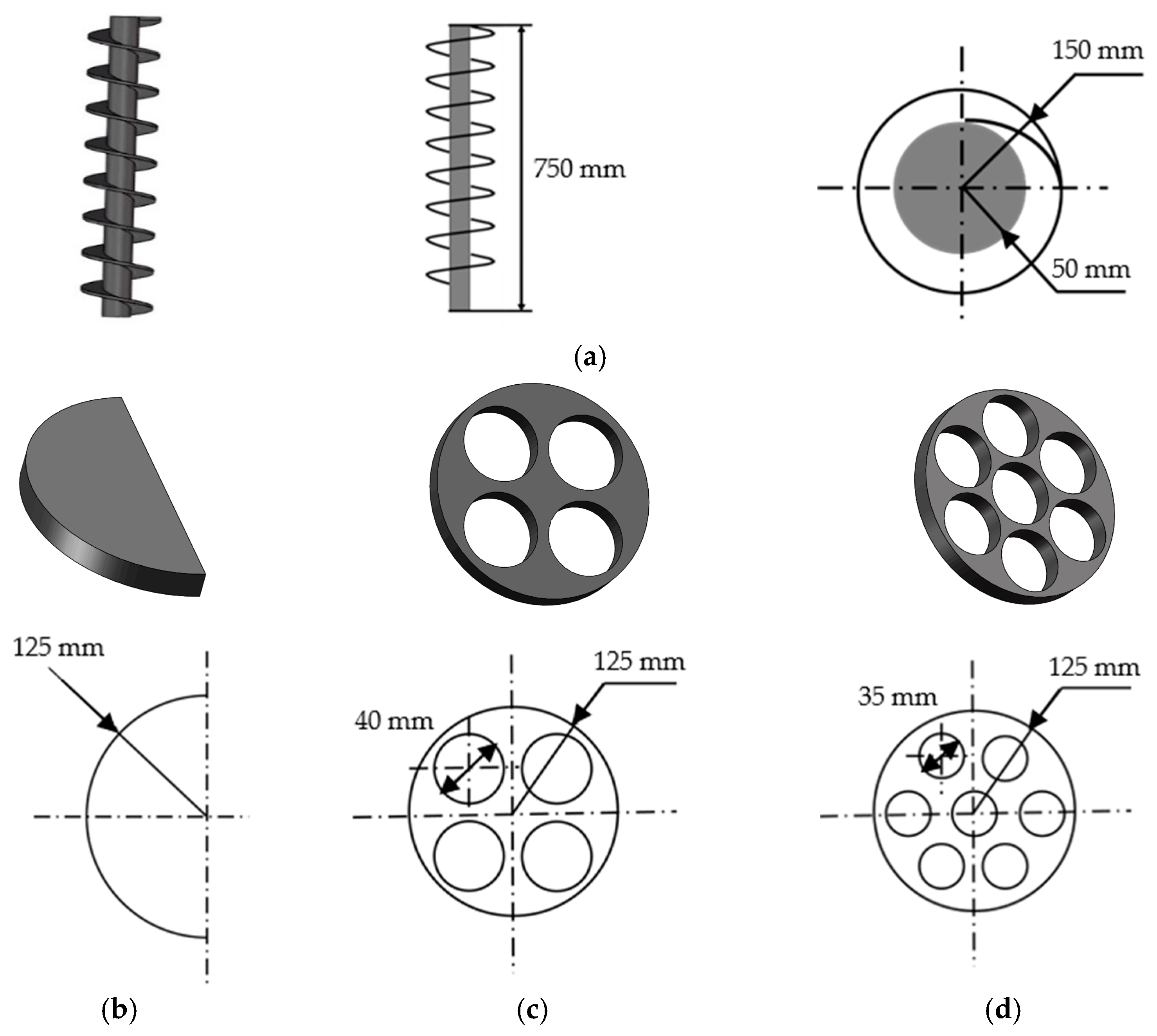
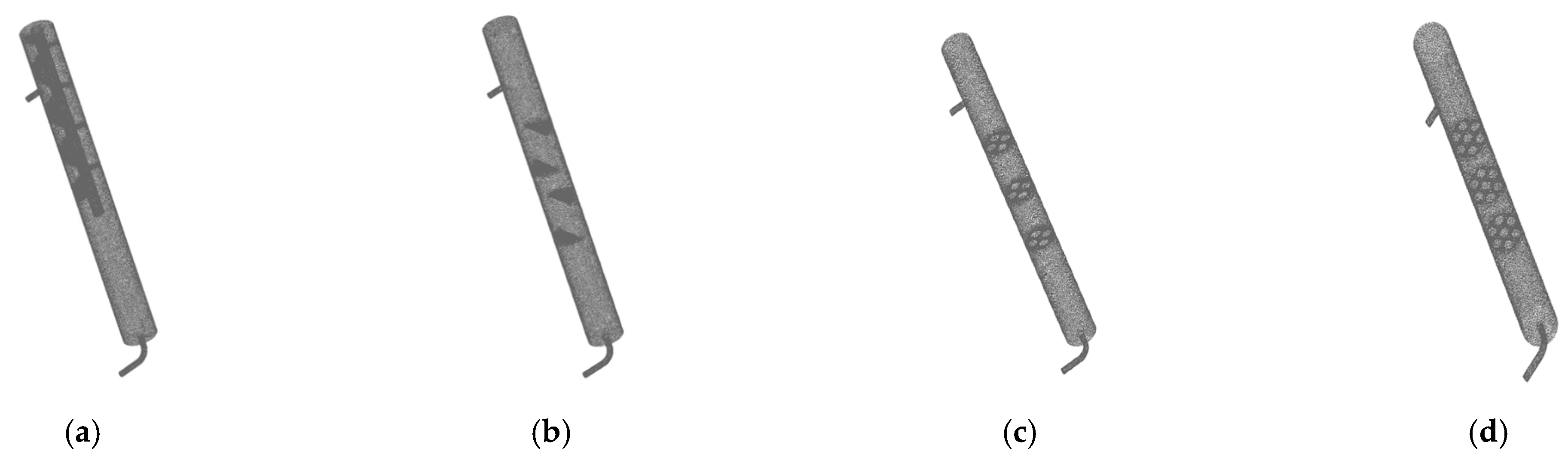
4.2. Geometric Modeling and Meshing

The simulated structure of the discrete pipe is shown in Figure 3. The total length of the pipe is 1500 mm, the diameter of the pipe body is 150 mm, and the diameter of the inlet and outlet pipelines is 25 mm. In order to facilitate the study, the pipe is divided into three divisions: inlet, coalescing and settling. The coalescing component is installed in the coalescing section to improve the oil and water separation ability of the pipe.
The coalescing components used in the experiment include the spiral track, semicircular baffle, four-hole plate and seven-hole plate. The spiral track is composed of a central core and a peripheral fluid track, which is half the length of the pipe. The spiral track is installed in the direction of the liquid flow and is tangent to the inner wall of the riser. The semicircular baffles are perpendicular to the direction of the liquid flow. The semicircular baffles are installed opposite to each other at a certain distance. The orifice plates are installed in groups of three at equal intervals perpendicular to the direction of the liquid flow. Figure 4 shows the model and dimensions of the coalescing components.
Fluent’s preprocessing module Gambit is used to model discrete pipes with different coalescing components. The discrete pipe adopts the division method of global control and local encryption. Tetrahedral mesh is used to partition the whole area, and unstructured mesh is used only in the local complex area. The coalescing components are divided by unstructured mesh, and the rest of the riser is divided by tetrahedral mesh. The velocity boundary condition is set at inlet, the outflow is set at the outlet, the wall boundary condition is set on pipe surface. Figure 5 shows the mesh division.

4.3. Numerical Simulation Results and Analysis

Four discrete pipes, i.e., spiral track, semicircle baffle, four-hole plate and seven-hole plate, were numerically simulated. The flow field of different coalescing components was observed, and their separation characteristics were studied qualitatively by the oil phase volume distribution cloud diagram. The origin of the coordinates is located below the side of the separator riser. The X and Y axes are set on the same plane. The flow direction of the fluid in the pipe is set to the Y direction and the transverse direction is set to the X direction.
Figure 6 shows the volume distribution of the oil phase in the spiral orbit. Red represents the highest concentration of the oil phase and blue represents the lowest; Figure 7, Figure 8 and Figure 9 use the same color scale. The volume fraction of the oil phase in the range of the spiral orbit is very high, indicating that the large area of contact between the mixture and the spiral orbit can promote the coalescence of oil droplets.
Figure 7 shows the oil phase volume distribution of the semicircular baffle. Analysis of the diagram shows that the mixture flows in the shape of an “S” near the baffle, generating eddy currents in the area below the baffle and forming a “dead zone”. Therefore, the volume fraction of oil phase volume decreases slowly in an “S” shape near the baffle and sharply below the baffle.
Figure 8 and Figure 9, respectively, show the oil phase volume distribution of the four-hole plate and seven-hole plate. The volume fraction of the oil phase decreases slowly along the pipe without sudden change. However, the oil phase volume fraction of the seven-hole plate is always smaller than that of the four-hole plate. Comparing the four kinds of coalescent components, the semicircular baffle has the most uneven volume distribution of the oil phase and the most unstable flow characteristics.
The volume distribution of the oil phase in each pipe is affected by the coalescing components. The orifice plate accelerates the coalescence of oil droplets by slowing the flow rate laterally. The orifice coalescing component accelerates the agglomeration of oil droplets by slowing down the flow velocity laterally. The seven-hole plate has more holes than the four-hole plate, which has a stronger ability to slow down the flow rate. The spiral orbit improves the effect of coalescence mainly by increasing the contact area between the emulsion and the component, and the oil volume fraction near the spiral orbit shows a high value. In contrast, the semicircular baffle has no significant effect on contact coalescence and slow flow rate coalescence, so its oil volume fraction distribution is the most uneven.

5. Laboratory Experiment

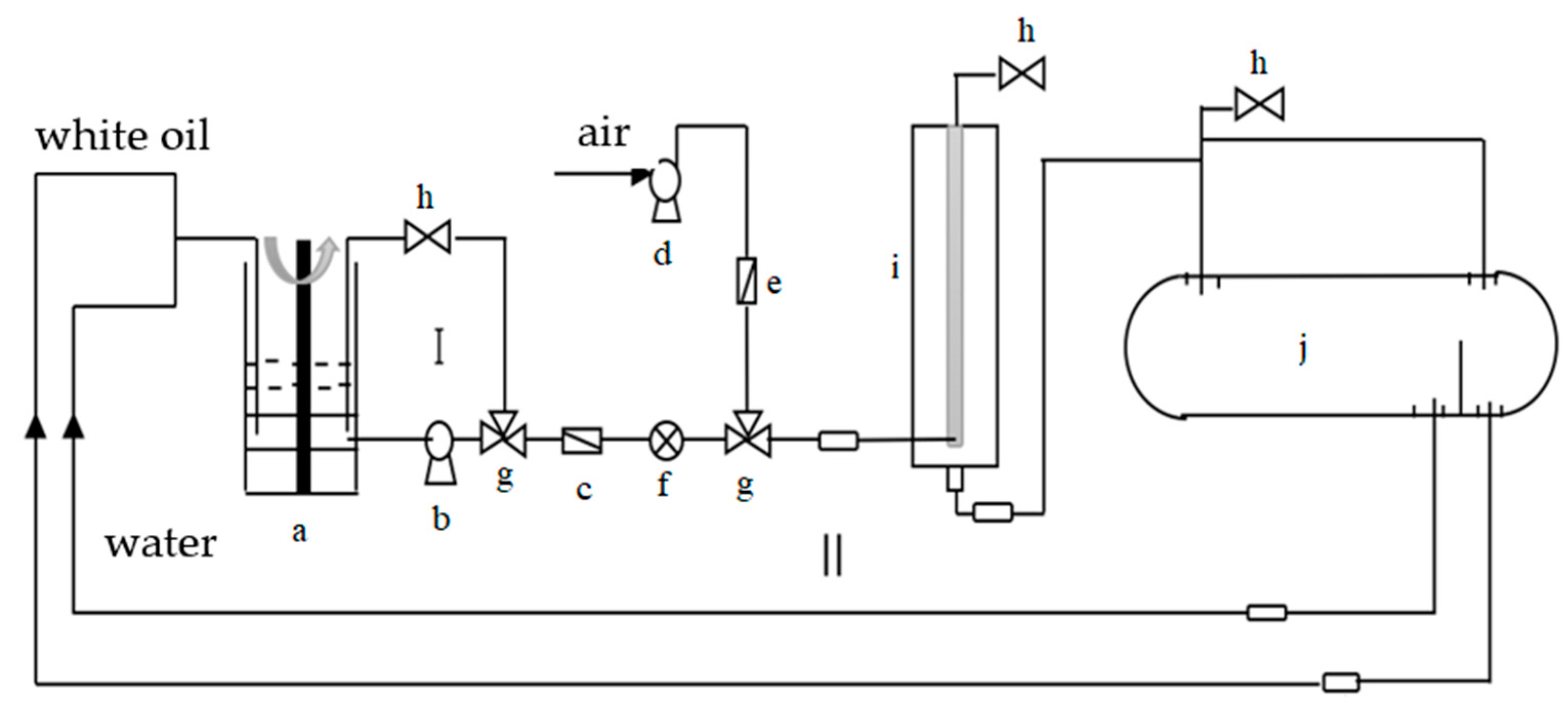
5.1. Experimental Procedures

After simulating the flow field of the riser with different coalescing components, it is found that the oil phase volume distribution in the pipe with a semicircular baffle is the most uneven, and the pipe with an orifice coalescing component is the most stable. To test the efficiency of the MMSS and verify the performance of each discrete pipe, the laboratory experimental system is built, as shown in Figure 10. The specific operation steps can be divided into three parts: the oil–water mixture, multistage separation of mixed liquid and sampling measurement.
When carrying out the experiment, the oil and water mixture with a white oil concentration of 10% was first configured. The specific operation is as follows: turn on loop I and open the switch of the mixer. Through the high rotation of the mixer impeller, the oil and water mixture was fully sheared and emulsified. This process lasted for 70 min.
Circulation I was closed after the oil and water mixture was configured. According to the research requirements, the system was adjusted, and loop II was connected. After running the experiment for 30 min, 250 mL samples were taken at the outlet of the vertical separator under different working conditions. A digital microscope was used to observe the shape and measure the particle size of the sample droplets. At the end of the oil and water separation process, liquid samples were taken at the water outlet and oil outlet of the horizontal separator. The water content concentration of the oil outlet and the oil concentration of the water outlet were measured by distillation and a ultraviolet spectrophotometer, respectively.

5.2. Experimental Results and Analysis

5.2.1. Separation Effect of the Separation System

In order to test the optimization effect of the MMSS and highlight the practical value of the parallel vertical separator (Tianjin Yixiang Junda Energy Technology Co., Ltd., Tianjin, China), a set of experiments were designed to compare the separation efficiency of the MMSS and horizontal separator (Tianjin Yixiang Junda Energy Technology Co., Ltd., Tianjin, China). In the experiment, the parallel vertical separator was fully open, and the flow rate was 1.5 m3/h. Timing was started while turning on loop II. Figure 11 and Figure 12 show the changes in water and oil contents at the oil outlet with settlement time.
By analyzing Figure 11 and Figure 12, it can be seen that both the water and oil contents at the water outlet decreased with the increase of settling time in the first 30 min, which was in the stage of oil and water separation. After 30 min, the curve changed gently, and the oil–water separation was finished. Compared with a single horizontal separator, the separation efficiency of the MMSS was improved, and the water content at the oil outlet was reduced by 3.0%. This is because the emulsion flowing into the MMSS can be separated twice. The primary separation is carried out in the parallel vertical separator, and the coalescing components placed in the pipes can accelerate the coalescence of the oil droplets. From the distribution cloud diagram of oil phase volume fraction, it can be seen that the oil phase volume fraction at the outlet of the discrete pipe decreased significantly compared with the inlet. A part of the oil droplets in the emulsion are separated, which reduces the oil content of the emulsion flowing into the horizontal separator. The emulsion with reduced oil content flows into the horizontal separator for secondary sedimentation separation. In addition, the settlement time of the emulsion in MMSS is longer than that in the single horizontal separator, which will also improve the separation effect to a certain extent. It is worth noting that the oil content at the water outlet of the two separators is essentially the same after 30 min. This indicates that there is still a small part of oil droplets in the outlet fluid that cannot be removed by gravity separation.

5.2.2. Separation Efficiency of Different Coalescing Components

After comparing the separation effect between the MMSS and a single horizontal separator, the effect of the coalescing component in the discrete pipe on the separation efficiency was further studied. During the experiment, the inlet flow of the separator was 1.5 m3/h. The working state of the five pipes is controlled by adjusting the switch, including six working states: connecting blank pipe, semicircle baffle, spiral track, four-hole plate, seven-hole plate and fully open.
Firstly, the vertical separator was studied to verify the optimization effect of the vertical separator. After the experiment was run for 30 min, the liquid at the outlet of the vertical separator under six working conditions was sampled successively. The droplet morphology was observed by a digital microscope, as shown in Figure 13.
The particle size of oil droplets can be measured by micrographs. The diameter of each droplet was plotted in the picture. Finally, the average diameter and distribution of droplets were obtained by comprehensive statistics. Table 1 shows the oil droplet size. The larger the oil droplet size, the better the coalescence effects. By analyzing the above six groups of experimental result, it is found that the oil droplet size of the blank pipe is the smallest. When the five rises are fully opened, the continuous oil layer appears at the outlet of the vertical separator. Under the experimental conditions, the oil droplet coalescence capacity of the four coalescing components is ordered as follows: seven-hole plate > spiral track > four-hole plate > semicircle baffle.
After the oil and water separation process is finished, the oil concentration at the water outlet and water concentration at the oil outlet were measured, respectively, under six working conditions. The blank tube was used as a control experiment to analyze the changes of sample data under the other five working states. The higher the sample reduction percentage, the stronger the coalescence ability of the coalescing components. Table 2 shows the values of the samples.
It is evident from Table 2 that the five pipes all open have the largest percentage reduction. When the riser with the coalescing component works alone, the oil content at the water outlet and water content at the oil outlet decrease to different degrees compared with the blank pipe. The ability of each coalescing component to improve the system efficiency is highly consistent with the ability of coalescent oil droplets, which is seven-hole plate > spiral track > four-hole plate > semicircle baffle. Among the four coalescing components, the orifice group was installed perpendicular to the oil and water emulsion flow direction. The number of holes in the seven-hole plate is larger, the ability to slow down the flow velocity is stronger, and the separation time of the emulsion in the separator is longer. Therefore, the separation efficiency of the seven-hole plate is higher than the four-hole plate. The contact area between the spiral track and the emulsion is the largest, but the ability to slow down the liquid flow velocity is weaker than the orifice group. The separation effect of the spiral track is between the seven-hole plate and the four-hole plate. The semicircular baffle has the smallest contact area with the emulsion and has the worst slow flow ability to the liquid flow, so the separation effect is the worst.

5.2.3. Influence of Coalescing Components on System Separation Efficiency at Different Volumetric Flow Rates

In order to study the effect of coalescing component on system separation efficiency under different volumetric flow rates, the inlet volumetric flow rates can be adjusted successively to 1.0 m3/h, 1.2 m3/h, 1.5 m3/h, 1.8 m3/h, 2.0 m3/h. The water content line diagram at the oil outlet of the five discrete risers under different volumetric flow rates is drawn and analyzed.
It can be seen from Figure 14 that the water content at the oil outlet of the separator increases with the increase of inlet flow under the five working conditions. When the inlet flow is less than 1.6 m3/h, the performance of the coalescing component is as follows: spiral track > seven-hole plate > four-hole plate > semicircle baffle. However, when the inlet flow is greater than 1.6 m3/h, the coalescence performance of the spiral track deteriorates rapidly, and the coalescence performance is as follows: seven-hole plate > four-hole plate > spiral orbit > semicircle baffle. It can be seen that the coalescence performance of the spiral track is significantly affected by the flow rate; it is superior under the condition of a small flow rate. The coalescence performance of the orifice element is not obviously affected by flow rate, which is suitable for large flow rate separation. The semicircular baffle shows the smallest improvement in system separation efficiency.
The main mechanism of increasing droplet collision probability and coalescence rate is different for different coalescing components. The spiral track mainly increases the droplet collision probability by increasing the contact area between the emulsion and the coalescent plate. It has no obvious effect on the rectifying and slowing flow of the emulsion, so it performs better under the condition of small flow.
The seven-hole plate and four-hole plate increase coalescence efficiency by slowing the flow rate laterally. Therefore, the greater the inlet flow, the more obvious the slow flow effect of the orifice plate. The circular holes of the seven-hole plate are smaller and more densely distributed than those of the four-hole plate, which further increases the probability of contact coalescence of oil droplets. Therefore, the coalescence performance of the seven-hole plate is always better than the four-hole plate under the same condition.

6. Conclusions

(1)
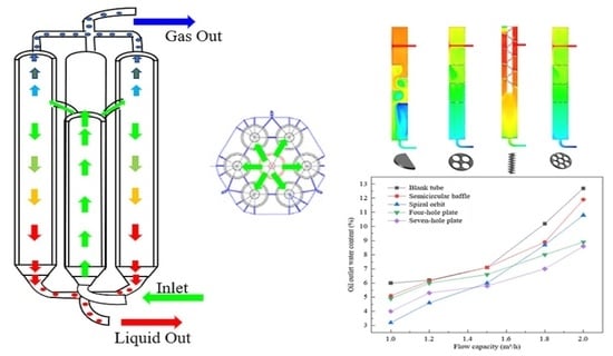
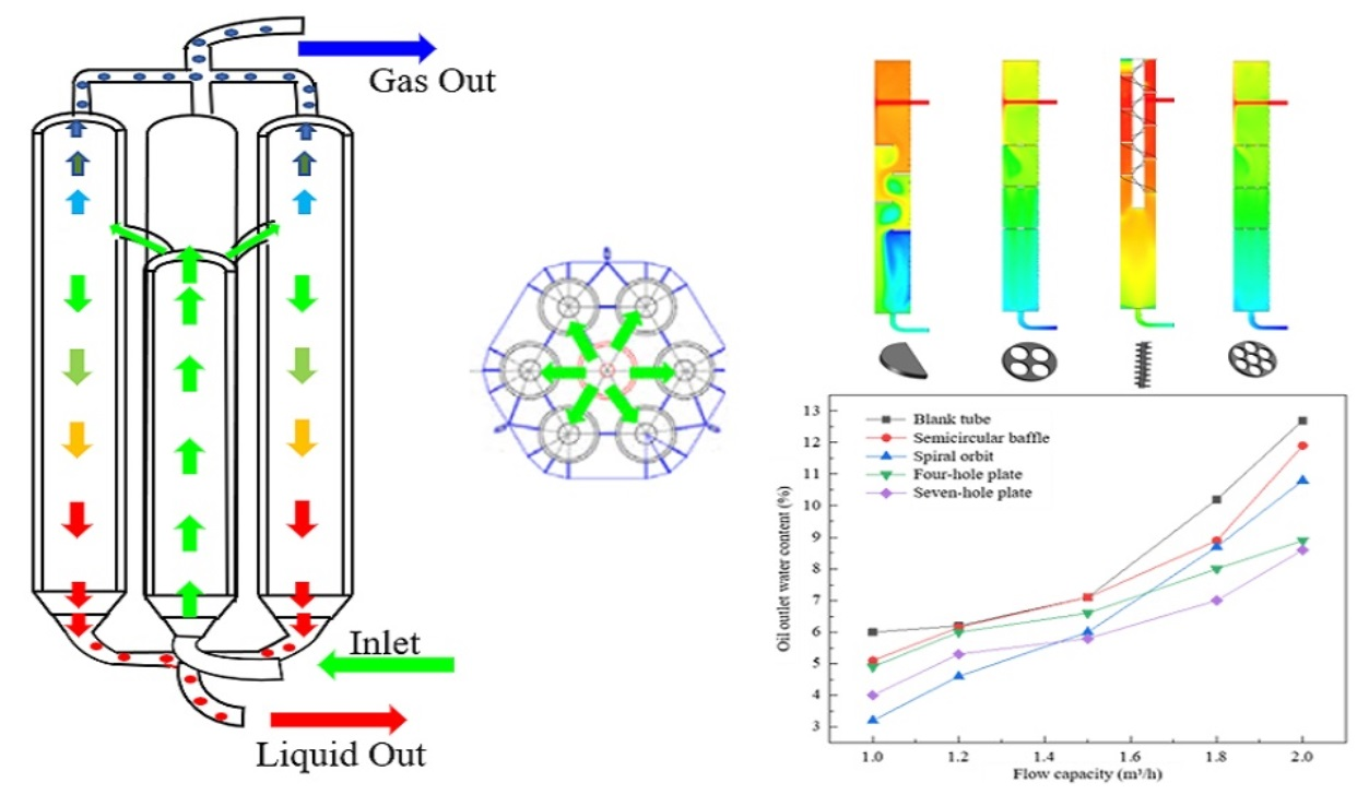
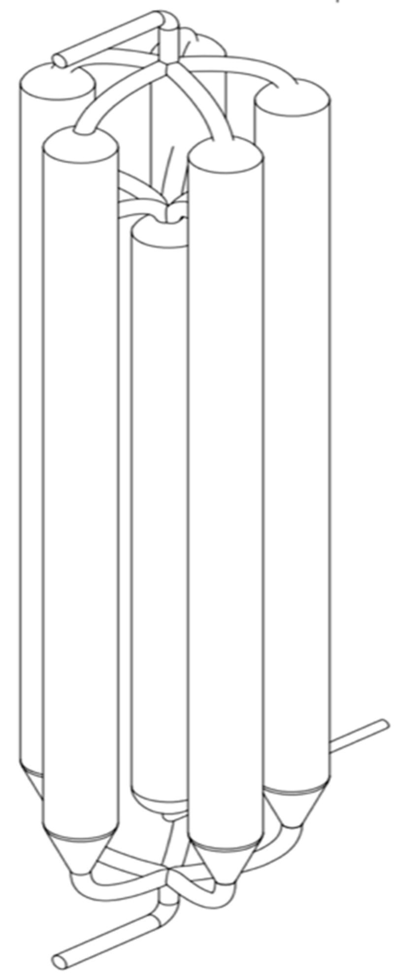
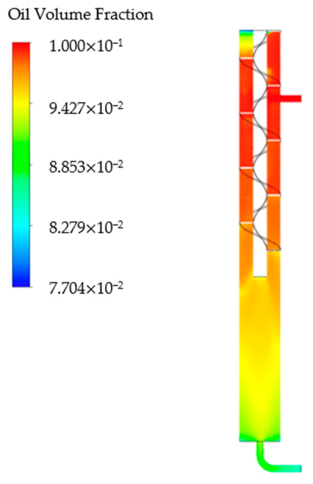
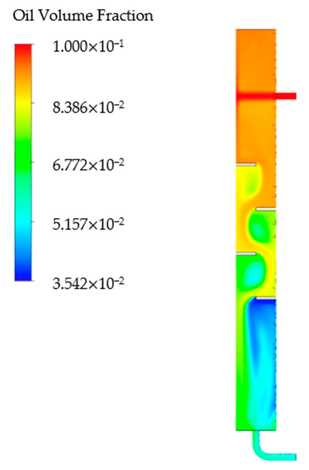
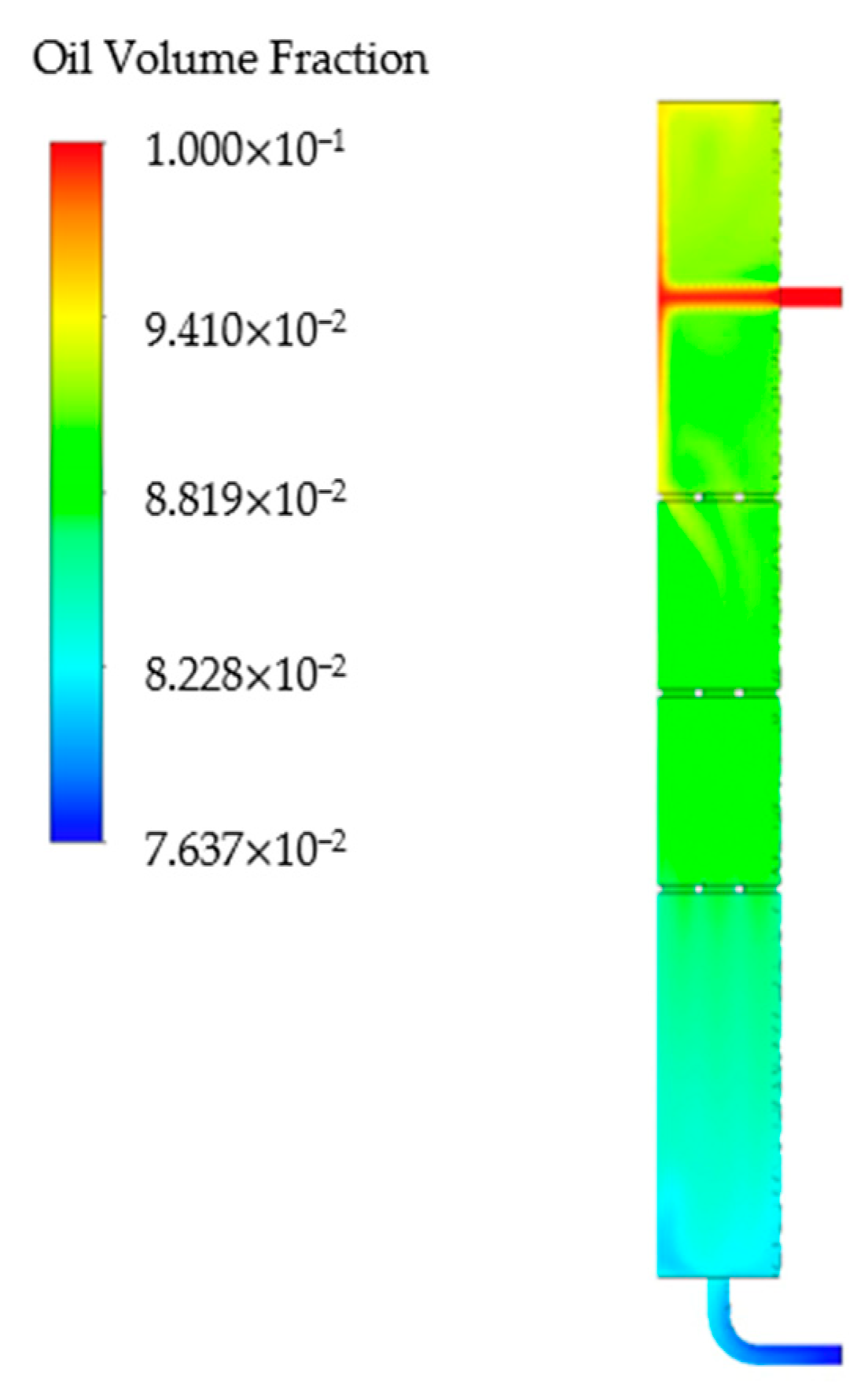
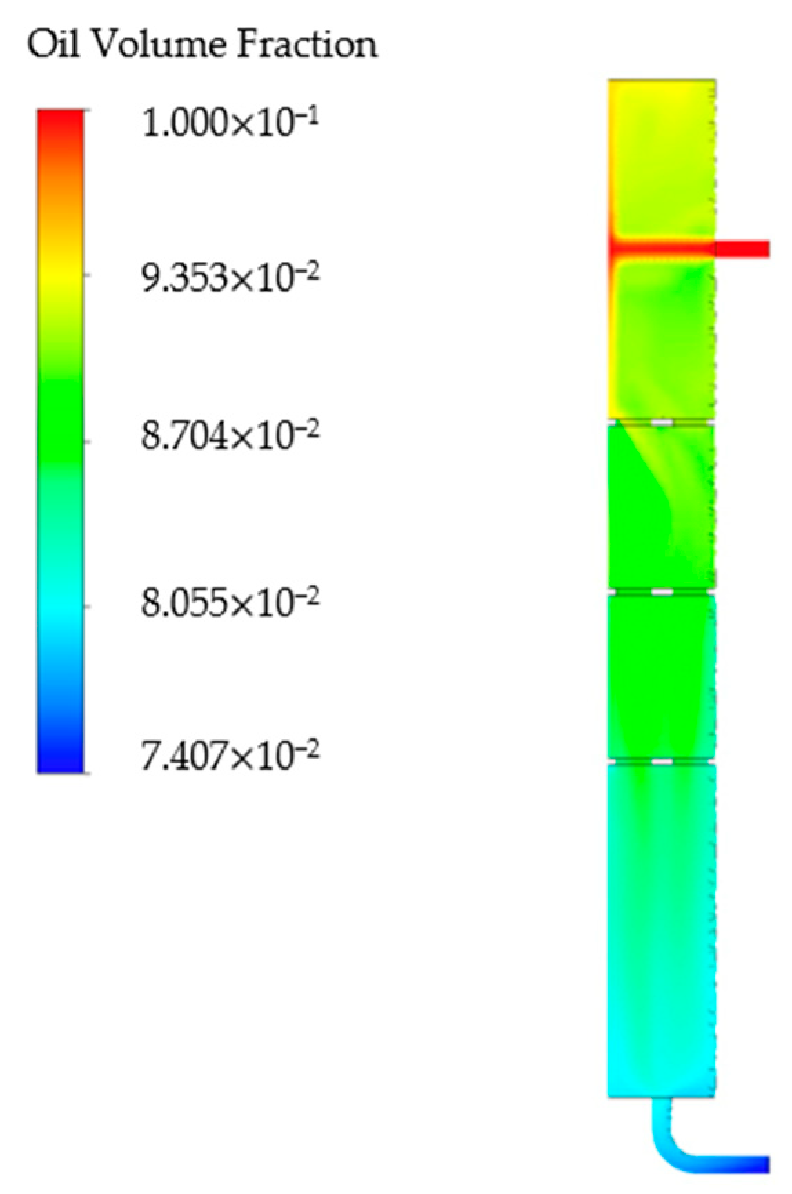
Numerical simulation of the vertical separator was carried out by Fluent software. In order to clarify the separation mechanism of parallel risers and the separation ability of a single pipe, the flow fields of pipes with different coalescing components were studied. The results show that the oil phase volume fraction distribution of the semicircle flapper is the most uneven, while the flow field of the orifice coalescing component is the most stable. Affected by contact with coalescence, the oil phase volume fraction in the vicinity of the spiral orbit coalescing component is at a high level.
(2)
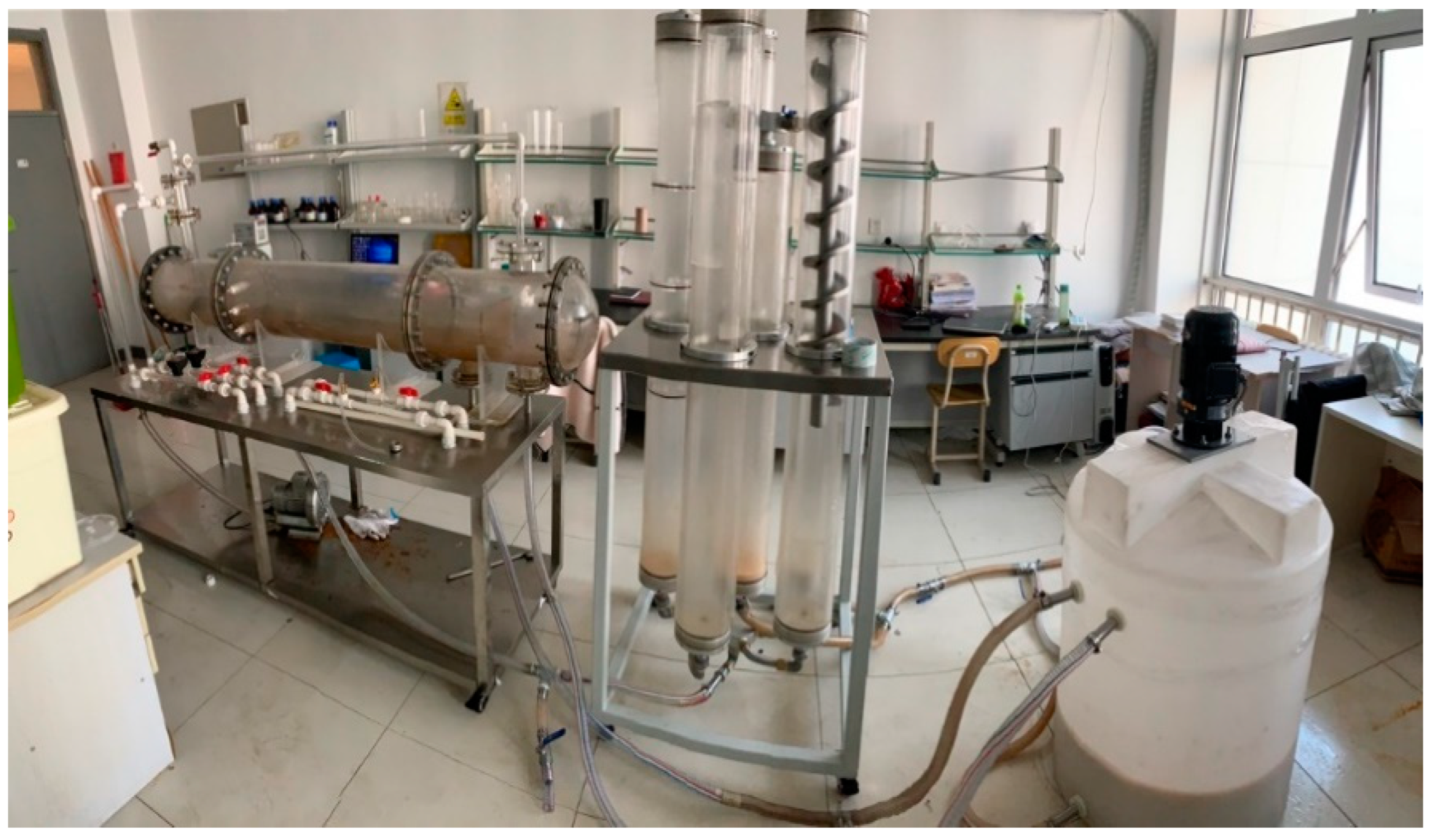
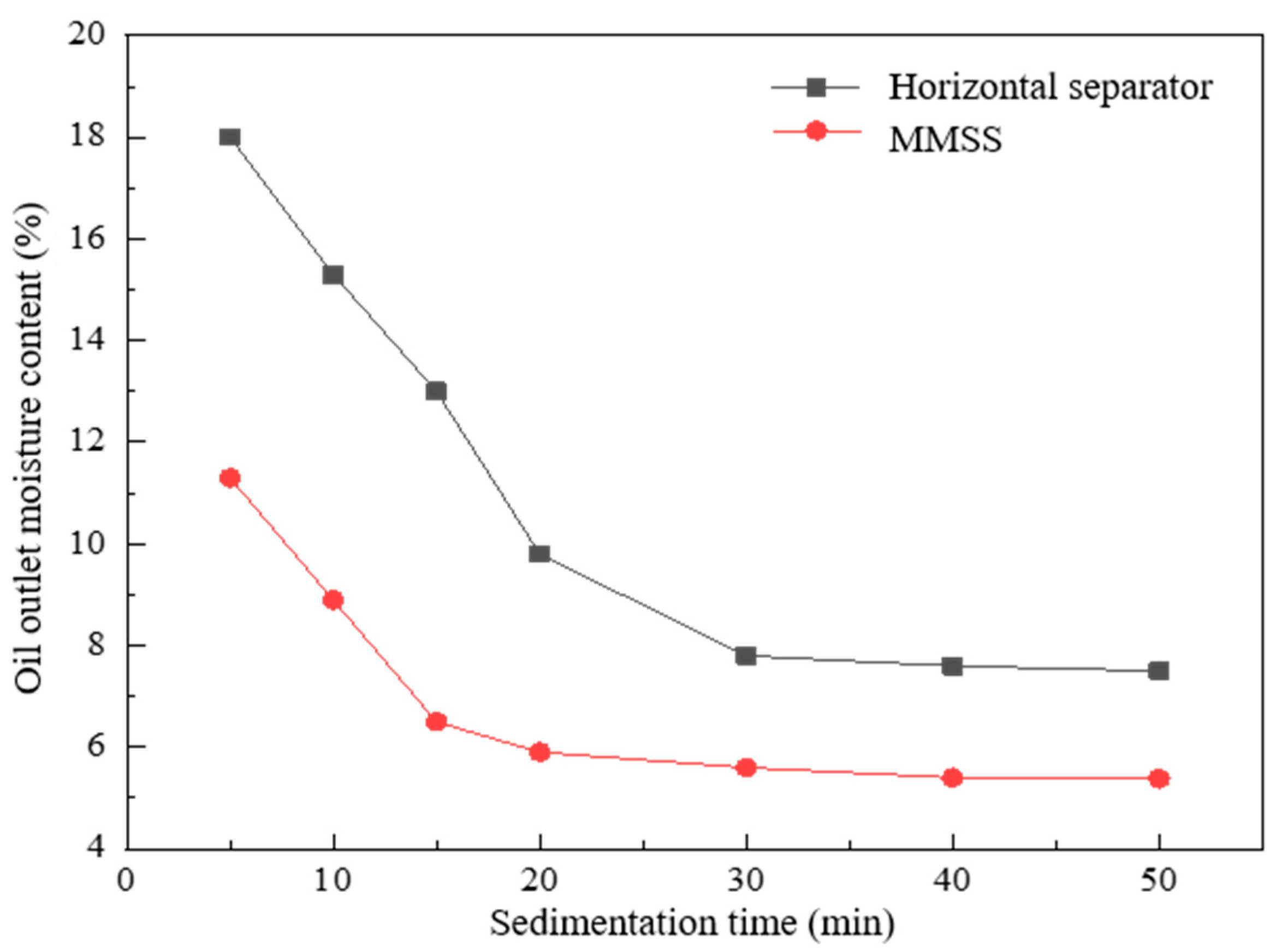
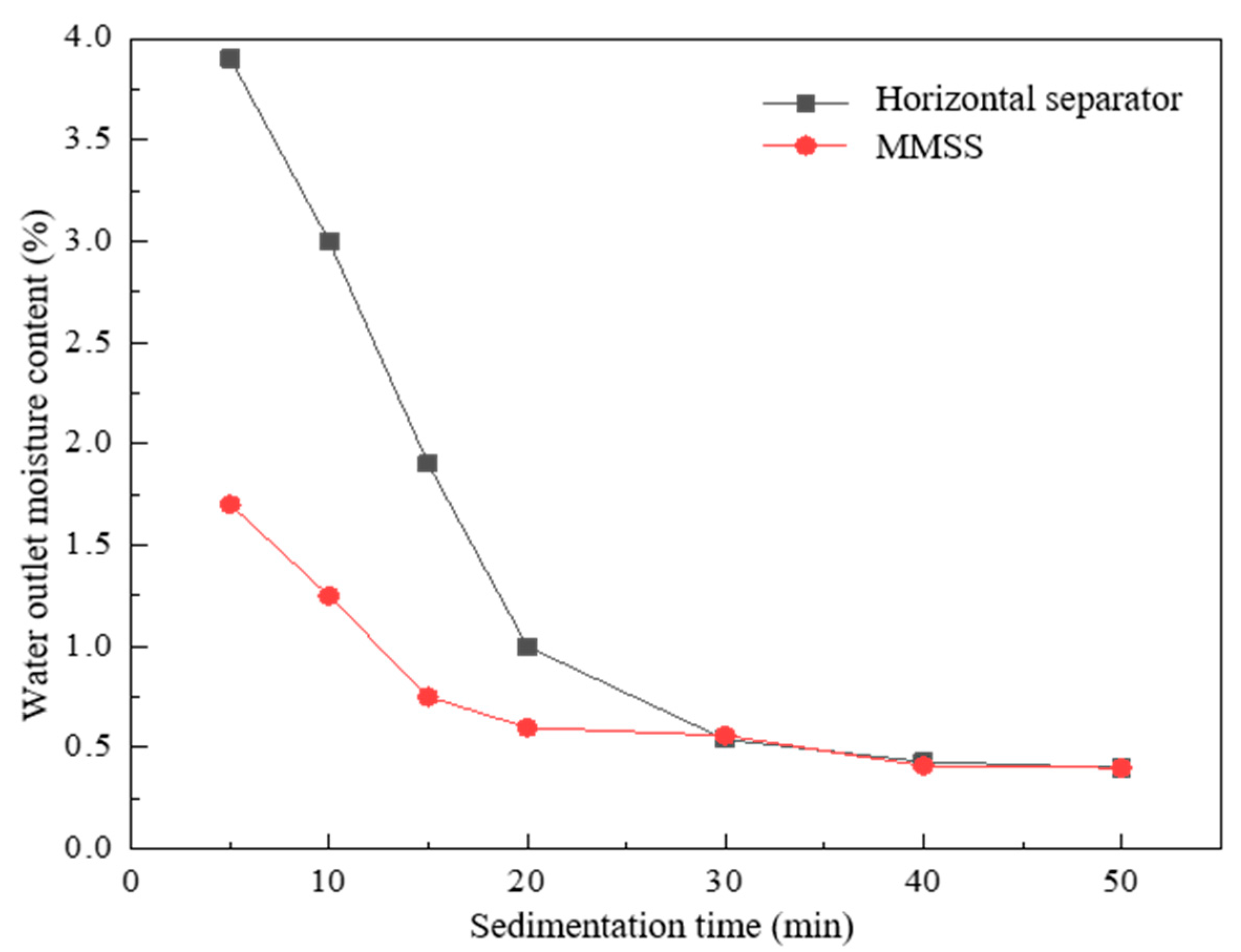
Laboratory experiments were carried out to study the separation effect of the multiphase oil–water separation system. The results show that the water content at the oil outlet of the new separation system is 3% less than the horizontal separator, and the new separation system has a better separation effect than the horizontal separator.
(3)
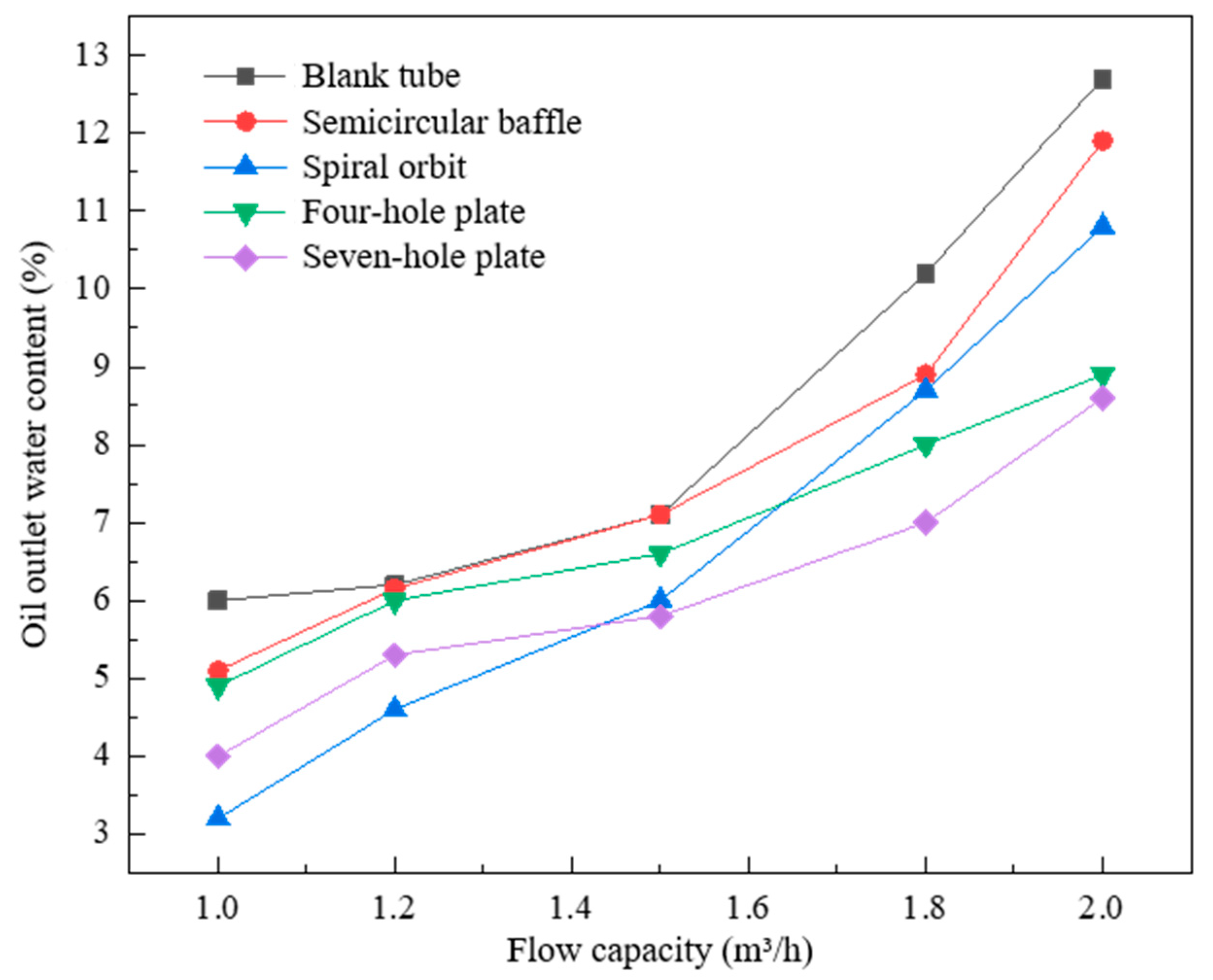
The numerical simulation results of the parallel vertical separator are in good agreement with the experimental results. The semicircular coalescing component has the worst separation effect. Under the condition that the inlet flow is less than 1.6 m3/h, the water content at the oil outlet of the spiral track is the lowest. It can be seen that the spiral track is suitable for small volumetric flow rate separation. In contrast, the orifice coalescing component can still maintain a lower water content at the oil outlet under the condition of large flow, which performs well at a large volumetric flow rate.
(4)
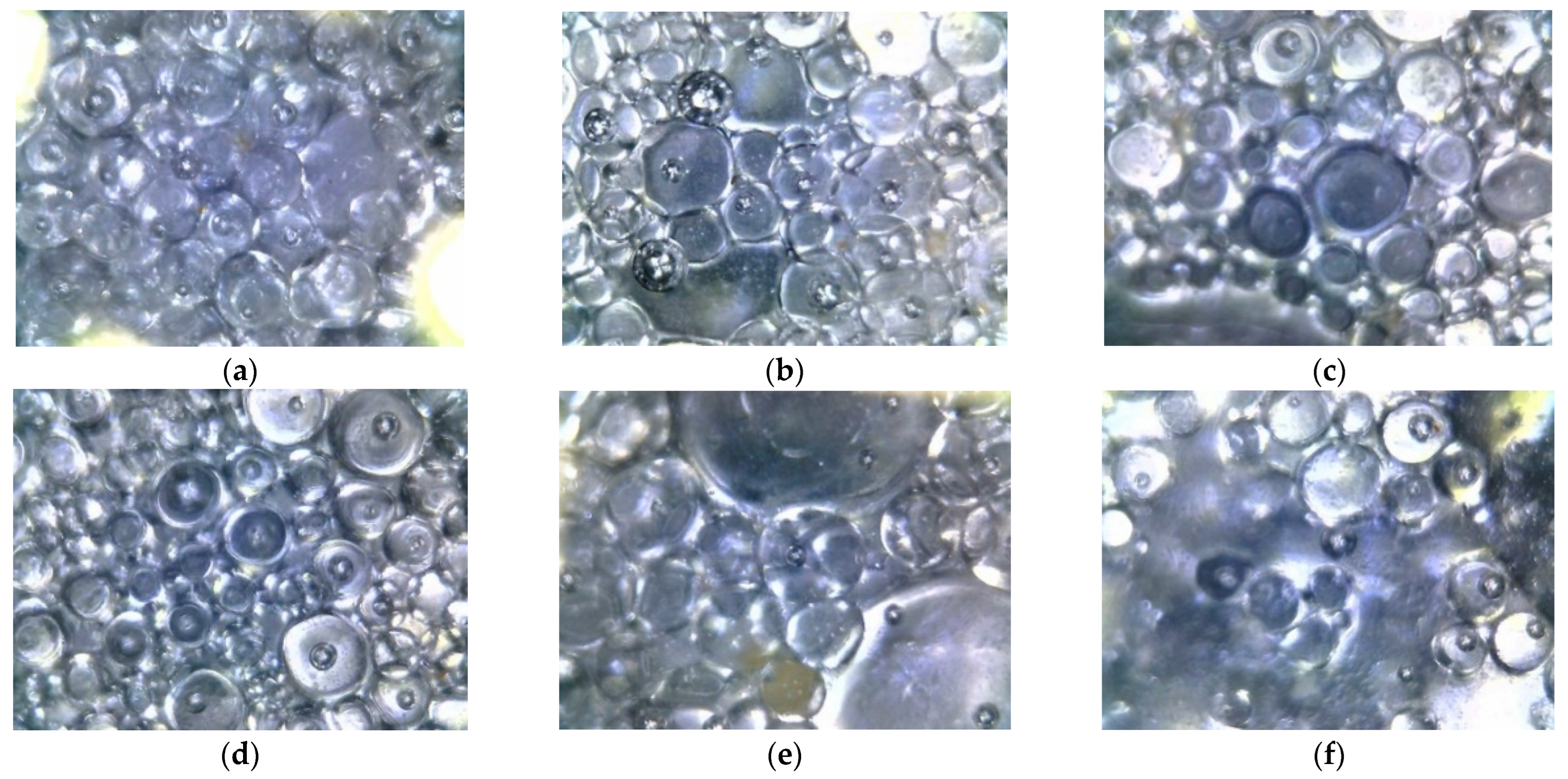
There are still some deviations in this experiment. There is a certain error of time in the sampling and measurement at the outlet, which affects the droplet morphology in the emulsion. In addition, different temperatures in the laboratory will also have an impact on the oil viscosity.

Author Contributions

Conceptualization, X.C., J.Z. and J.J.; data curation, J.Z. and J.J.; formal analysis, X.C. and Y.L.; funding acquisition, X.C. and L.Z.; methodology, X.C. and L.Z.; project administration, X.C. and H.P.; software, Y.L.; supervision, Y.L. and H.P.; validation, X.C. and L.Z.; writing—original draft, X.C. and L.Z.; writing—review and editing, J.J., Y.L., H.P. and L.Z. All authors have read and agreed to the published version of the manuscript.

Funding

This work was supported by the National Natural Science Foundation of China under Grant 51874335, 52274057 and 52074340, the Major Scientific and Technological Projects of CNPC under Grant ZD2019-183-008, the Major Scientific and Technological Projects of CNOOC under Grant CCL2022RCPS0397RSN, the Science and Technology Support Plan for Youth Innovation of University in Shandong Province under Grant 2019KJH002, and 111 Project under Grant B08028.

Data Availability Statement

All data related to the manuscript are available in the manuscript.

Conflicts of Interest

The authors declare no conflict of interest.

References

  1. Wu, Y.; Xu, J. Oil and water separation technology. Adv. Mech. 2015, 45, 179–216. [Google Scholar]
  2. Lv, J.; Kang, Y.; Wang, Z.; Peng, F. Research progress of oil-water separation technology and equipment in oilfield. Petro-Chem. Equip. 2019, 48, 69–75. [Google Scholar]
  3. Gupta, R.K.; Dunderdale, G.J.; England, M.W.; Hozumi, A. Oil/water separation techniques: A review of recent progresses and future directions. J. Mater. Chem. A 2017, 5, 16025–16058. [Google Scholar] [CrossRef]
  4. Behin, J.; Aghajari, M. Influence of water level on oil–water separation by residence time distribution curves investigations. Sep. Purif. Technol. 2008, 64, 48–55. [Google Scholar] [CrossRef]
  5. Mostafaiyan, M.; Saeb, M.R.; Alorizi, A.E.; Farahani, M. Application of evolutionary computational approach in design of horizontal three-phase gravity separators. J. Pet. Sci. Eng. 2014, 119, 28–35. [Google Scholar] [CrossRef]
  6. Frising, T.; Noïk, C.; Dalmazzone, C. The liquid/liquid sedimentation process: From droplet coalescence to technologically enhanced water/oil emulsion gravity separators: A review. J. Dispers. Sci. Technol. 2006, 27, 1035–1057. [Google Scholar] [CrossRef]
  7. Zhang, L.; He, L.; Wang, T.; Lv, Y.; He, Z. Researches on the numerical simulation and optimum of the coalescing components of gravity separators. Chem. Eng. Mach. 2008, 35, 17–21. [Google Scholar]
  8. Wang, Z.; Zhang, K.; Zhang, J.; Chen, G.; Ma, X.; Xin, G.; Kang, J.; Zhao, H.; Yang, Y. Deep reinforcement learning and adaptive policy transfer for generalizable well control optimization. J. Pet. Sci. Eng. 2022, 217, 110868. [Google Scholar] [CrossRef]
  9. Wang, G.; He, L.; Lv, Y.; Chen, Z. Study on oil water separation behavior of gravity separator. Pet. J. 2006, 27, 112–115. [Google Scholar]
  10. Acharya, T.; Casimiro, L. Evaluation of flow characteristics in an onshore horizontal separator using computational fluid dynamics. J. Ocean Eng. Sci. 2020, 5, 261–268. [Google Scholar] [CrossRef]
  11. Ye, W.; Qiu, T.; Chen, J.; Han, D.; Gao, Y. The structure optimization and separation performance simulation of single-double stage gas-liquid gravity separator. Chem. Eng. Mach. 2017, 44, 322–327. [Google Scholar]
  12. He, L.; Yang, G.; Xiaohan, P.; Guoxing, Z.; Lichen, Z. Progress and prospect of downhole cyclone oil-water separation with single-well injection-production technology. Acta Pet. Sin. 2018, 39, 463. [Google Scholar]
  13. Zhou, N.; Gao, Y.; An, W.; Yang, M. Numerical simulation of oil-water separation efficiency of a hydrocyclone. Chin. J. Environ. Eng. 2012, 6, 2953–2957. [Google Scholar]
  14. Ai, Z.; He, H.; Nu, G.; Xiao, L.; Ma, H. Optimization Study of the Entrance Structure of Oil-Water Separation Hydrocyclone. China Pet. Mach. 2007, 35, 5–9. [Google Scholar]
  15. Yin, F.; Xue, X.; Zhang, C.; Zhang, K.; Han, J.; Liu, B.; Wang, J.; Yao, J. Multifidelity genetic transfer: An efficient framework for production optimization. SPE J. 2021, 26, 1614–1635. [Google Scholar] [CrossRef]
  16. Zeng, R.; Yang, Y. The numerical simulation of the flow field of the oil-water cyclone separator. China Pet. Mach. 2011, 39, 24–27+96. [Google Scholar]
  17. Zhang, J.; Chen, D.; Lv, R.; Li, Y.; Chen, L.; Kong, X. Influence of Structural Parameters on Separation Performance of Gas-liquid Cyclone Separator for Hydraulic Oil Tank. Res. Sq. 2022, in press. [Google Scholar]
  18. de Luna, F.D.T.; Santos, B.R.G.; de Araújo, M.V.; dos Santos, E.B.; de Farias Neto, S.R.; de Lima, A.G.B. Numerical study of water-oil separation in cyclonic separators. Int. J. Model. Simul. Pet. Ind. 2015, 9, 13–19. [Google Scholar]
  19. Liu, T.; Fan, Y.; Yuan, S.; Yu, X. Effect of PEX coalescer on oil-water separation performance. Nat. Gas Chem. Industry. C1 Chem. Chem. Ind. 2019, 44, 104–108. [Google Scholar]
  20. Zhang, L.; He, L.; Wang, T.; Lv, Y.; He, Z. Separating behavior with coalescence internals in separator. J. Chem. Eng. High. Educ. Inst. 2009, 23, 345–350. [Google Scholar]
  21. Jia, P.; Chen, J.; Cai, X.; Kong, L.; Wang, C.; Shang, C.; Zhang, M.; Shi, Y. Study on oil-water separation characteristics of hydrocyclone based on CFD⁃PBM numerical simulation. J. Petrochem. Univ. 2021, 34, 58–65. [Google Scholar]
  22. Liang, L.; Zhang, W.; Bai, Z.; Yang, X.; Luo, H.; Zhang, B. Experimental and simulation study on separation performance of coalescing structural parts within oil-water gravity separator. Mod. Chem. Ind. 2018, 38, 211–215. [Google Scholar]
  23. Gao, Z.; Liu, J.; Wang, D.; Shao, W.; Liu, N.; Fang, B. The detecting method for oil-water separation performance of coalescence. J. Filtr. Sep. 2016, 26, 6–10. [Google Scholar]
  24. Yang, Q.; Lu, H.; Li, Y.; Dai, P.; Pan, Z.; Liu, Y. Application and research progress of coalescence separation in oily wastewater treatment. Chin. J. Environ.-Ment. Eng. 2021, 15, 767–781. [Google Scholar]
  25. Qu, J.; Ni, L.; Liu, X.; Zhu, W. Reserch on the factors of impacting the coalescence efficiency. J. Filtr. Sep. 2009, 19, 14–16. [Google Scholar]
  26. Zhang, L.; Zhao, Y.; Zhang, K.; Qi, J. Experimental design on flow field of different components in gravity separator. Lab. Res. Explor. 2019, 38, 25–27+39. [Google Scholar]
  27. Pan, C.; Zhao, H.; Yu, P.; Zou, W.; Li, Y. Simulation study on influencing factors of oil-water separation in coalescing plate separator. China Pet. Mach. 2021, 49, 93–102. [Google Scholar]
  28. Huang, W.; He, X.; Deng, C.; Xu, B. Study on the intensification mechanism of oil-water separation process by using inclined plate pack. Adv. Eng. Sci. 2017, 49, 191–196. [Google Scholar]
  29. Zhu, M.; Wang, D.; Yin, X. Influencing factors of air-flotation process for treatment of polymer flooding oil-extraction wastewate. Water Purif. Technol. 2012, 31, 43–45. [Google Scholar]
  30. Saththasivam, J.; Loganathan, K.; Sarp, S. An overview of oil–water separation using gas flotation systems. Chemosphere 2016, 144, 671–680. [Google Scholar] [CrossRef]
  31. Rajak, V.; Relish, K.; Kumar, S.; Mandal, A. Mechanism and kinetics of separation of oil from oil-in-water emulsion by air flotation. Pet. Sci. Technol. 2015, 33, 1861–1868. [Google Scholar] [CrossRef]
  32. Li, J.; Xue, Q.; He, C.; Shen, Z.; He, Z. Research progress of oily sewage with air flotation technology. Guangdong Chem. Ind. 2015, 42, 103–104+85. [Google Scholar]
  33. Wei, Y.; Qi, H.; Gong, X.; Zhao, S. Specially wettable membranes for oil–water separation. Adv. Mater. Interfaces 2018, 5, 1800576. [Google Scholar] [CrossRef]
  34. Zhang, L.; Wang, S.; Zhang, K.; Zhang, X.; Sun, Z.; Zhang, H.; Chipecane, M.T.; Yao, J. Cooperative artificial bee colony algorithm with multiple populations for interval multiobjective optimization problems. IEEE Trans. Fuzzy Syst. 2018, 27, 1052–1065. [Google Scholar] [CrossRef]
  35. Lin, X.; Hong, J. Recent advances in robust superwettable membranes for oil–water separation. Adv. Mater. Interfaces 2019, 6, 1900126. [Google Scholar] [CrossRef]
  36. Nakamura, K.; Nakamura, J.; Matsumoto, K. Filtration and backwashing behaviors of the deep bed filtration using long length poly-propylene fiber filter media. J. Taiwan Inst. Chem. Eng. 2019, 94, 31–36. [Google Scholar] [CrossRef]
  37. Wei, J.; Duan, L.; Wei, J.; Hoffmann, E.; Song, Y.; Meng, X. Lead removal from water using organic acrylic amine fiber (AAF) and inorganic-organic P-AAF, fixed bed filtration and surface-induced precipitation. J. Environ. Sci. 2021, 101, 135–144. [Google Scholar] [CrossRef]
  38. Govedarica, D.D.; Sokolović, R.M.Š.; Sokolović, D.S.; Sokolović, S.M. A novel approach for the estimation of the efficiency of steady-state fiber bed coalescence. Sep. Purif. Technol. 2013, 104, 268–275. [Google Scholar] [CrossRef]
  39. Brothers, J.E. Stokes’ theorem. Am. J. Math. 1970, 92, 657–670. [Google Scholar] [CrossRef]
  40. Kumar, N.; Mandal, A. Thermodynamic and physicochemical properties evaluation for formation and characterization of oil-in-water nanoemulsion. J. Mol. Liq. 2018, 266, 147–159. [Google Scholar] [CrossRef]
  41. Han, Y.; He, L.; Luo, X.; Lü, Y.; Shi, K.; Chen, J.; Huang, X. A review of the recent advances in design of corrugated plate packs applied for oil–water separation. J. Ind. Eng. Chem. 2017, 53, 37–50. [Google Scholar] [CrossRef]
  42. Wang, X.; Han, H. The gas-liquid separation experimental study of multi-cups anchor. Offshore Oil 2007, 01, 64–67. [Google Scholar]
  43. Yang, L.; Wang, J.; Jiang, Y.; Zou, L. Oil–water flow splitting in eccentric annular T-junction tubes—Experimental and CFD analysis. Chem. Eng. Sci. 2020, 228, 116000. [Google Scholar] [CrossRef]
Figure 1. Proposed multistage multiphase oil–water separation system.
Separations 09 00405 g001
Figure 2. Schematic diagram of the parallel vertical separator.
Separations 09 00405 g002
Figure 3. Geometric structure of discrete pipe.
Separations 09 00405 g003
Figure 4. Model diagram of coalescing components. (a) Spiral track model diagram; (b) semicircular baffle model diagram; (c) four-hole plate model diagram; and (d) seven-hole plate model diagram.
Separations 09 00405 g004
Figure 5. Meshing diagram of discrete pipes. (a) Mesh division of the spiral orbit, with an encrypted mesh of 89,900; (b) mesh division of the semicircular baffle, with an encrypted mesh of 72,000; (c) mesh division of the four-hole plate, with an encrypted mesh of 62,700; and (d) mesh division of the seven-hole plate, with an encrypted mesh of 66,300.
Separations 09 00405 g005
Figure 6. Oil phase volume distribution of the spiral orbit.
Separations 09 00405 g006
Figure 7. Oil phase volume distribution of semicircular baffle.
Separations 09 00405 g007
Figure 8. Oil phase volume distribution of four-hole plate.
Separations 09 00405 g008
Figure 9. Oil phase volume distribution of seven-hole plate.
Separations 09 00405 g009
Figure 10. Flow chart of the laboratory experiment. (a) Small mixing barrel; (b) booster pump; (c) liquid flowmeter; (d) gas pump; (e) gas flowmeter; (f) check valve; (g) tee; (h) bypass valve; (i) vertical separator; and (j) horizontal separator.
Separations 09 00405 g010
Figure 11. Change in water content of the oil outlet with settlement time.
Separations 09 00405 g011
Figure 12. Change in oil content of the water outlet with settlement time.
Separations 09 00405 g012
Figure 13. Microscopy images of oil droplet size at the outlet of the vertical separator under six working states. (a) Blank tube; (b) semicircular baffle; (c) spiral track; (d) four-hole plate; (e) seven-hole plate; (f) all five risers are open.
Separations 09 00405 g013
Figure 14. Water content at the oil outlet of different flow rates.
Separations 09 00405 g014
Table 1. Oil droplet size.
Blank Tube
/(μm)
Semicircular Baffle/(μm)Spiral Orbit
/(μm)
Four-Hole Plate/(μm)Seven-Hole Plate/(μm)All Risers Are Open
69.0371.4975.8072.9978.24
Table 2. Comparison of separation effects.
Blank TubeSemicircular BaffleSpiral OrbitFour-Hole PlateSeven-Hole Plate
Oil content reduction/%6.2513.310.214.820
Water content reduction/%6.91513.715.517.6
Publisher’s Note: MDPI stays neutral with regard to jurisdictional claims in published maps and institutional affiliations.

