


Theoretical Study of a Closed-Cycle Evaporation System for Seawater Desalination


Abstract
:1. Introduction
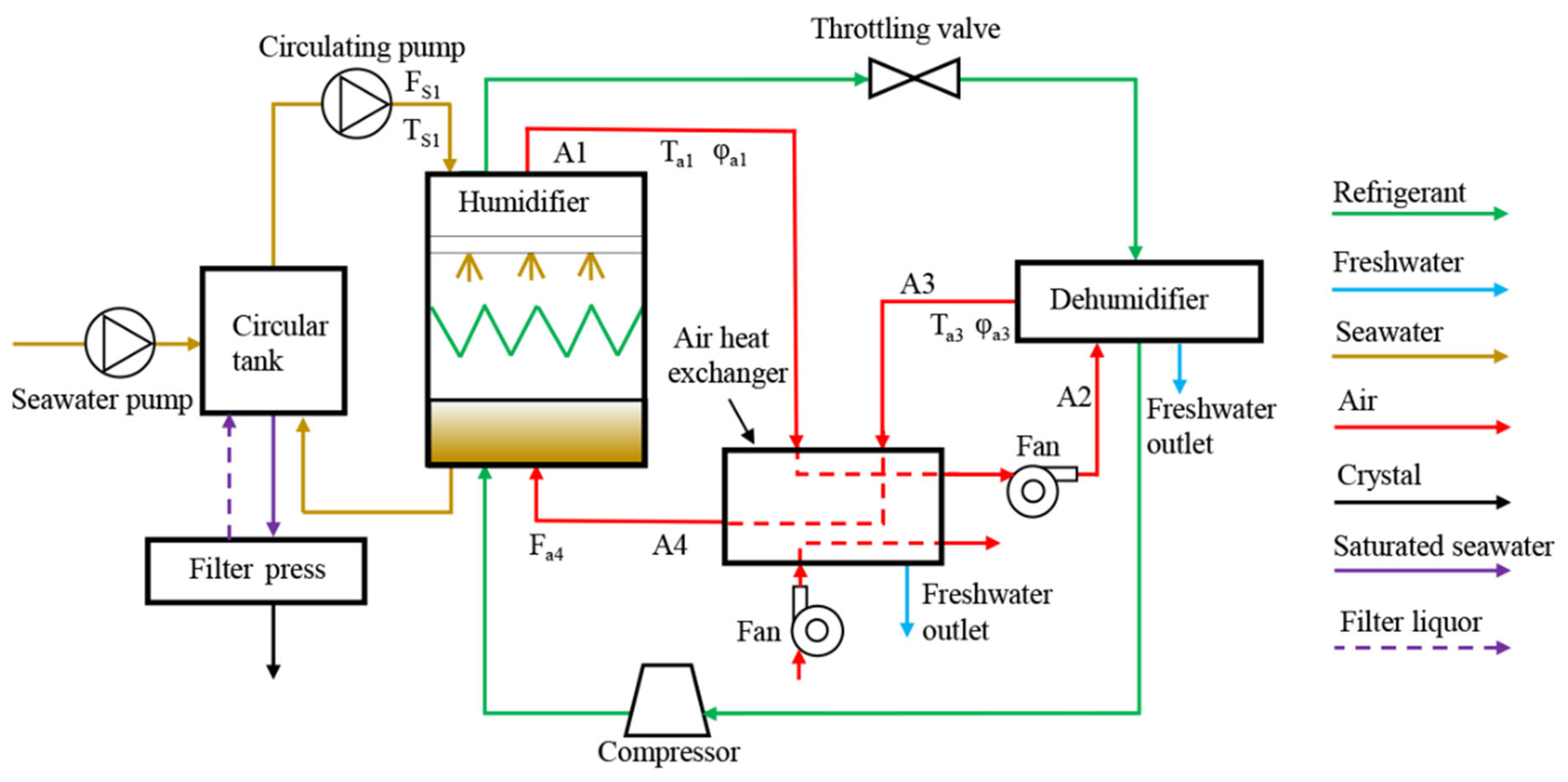
2. Description
- Seawater: Seawater is circulated in the circulation tank and the humidifier. The seawater is sprayed by a circulation pump onto a heat exchange coil inside the humidifier. The water molecules in the seawater absorb heat to form steam, and the remaining seawater participates in the next circulation.
- Air: The circulation fan is installed between the first dehumidifier and the second dehumidifier. Through the suction of the circulation fan, a large amount of air enters from the bottom of the humidifier and is heated and humidified. The nearly saturated air leaves the top of the humidifier and enters the two dehumidifiers where it is cooled and dehumidified, resulting in a large amount of freshwater.
- Refrigerant: The refrigerant is circulated through the humidifier, the second dehumidifier, and the compressor. The heat pump’s condensing end is represented by the heat exchanger coil of the humidifier, where the refrigerant is condensed and gives off heat. Meanwhile, the dehumidifier functions as the evaporating end of the heat pump, wherein the refrigerant gathers heat from the air.
3. Numerical Model
3.1. Sub-Model of the Humidifier
- (1)
- Humidifiers are not affected by external temperature and humidity;
- (2)
- The nature of seawater is stable;
- (3)
- The model is in a stable process.
3.2. Sub-Model of the Heat Pump Unit
3.3. Sub-Model of the First Dehumidifier
- Heat radiation losses have been ignored;
- Heat transfer occurs under steady-state conditions;
- The thermal resistance due to fins is neglected;
- The efficiency of the fins under humid conditions is the same as the efficiency of the dry fins;
- The following equation can be used to represent the heat transfer that occurs within the internal heat exchange channels of the first dehumidifier:
- b
- The heat exchange in the external heat exchange channels of the first-stage dehumidifier can be expressed as:
3.4. Sub-Model of the Second Dehumidifier
- (1)
- Heat radiation losses have been ignored;
- (2)
- The thermal resistance of the fins is ignored;
- (3)
- The efficiency of the fins under humid conditions is the same as that of the dry fins;
- (4)
- The evaporation temperature of the refrigerant is constant.
3.5. Validation
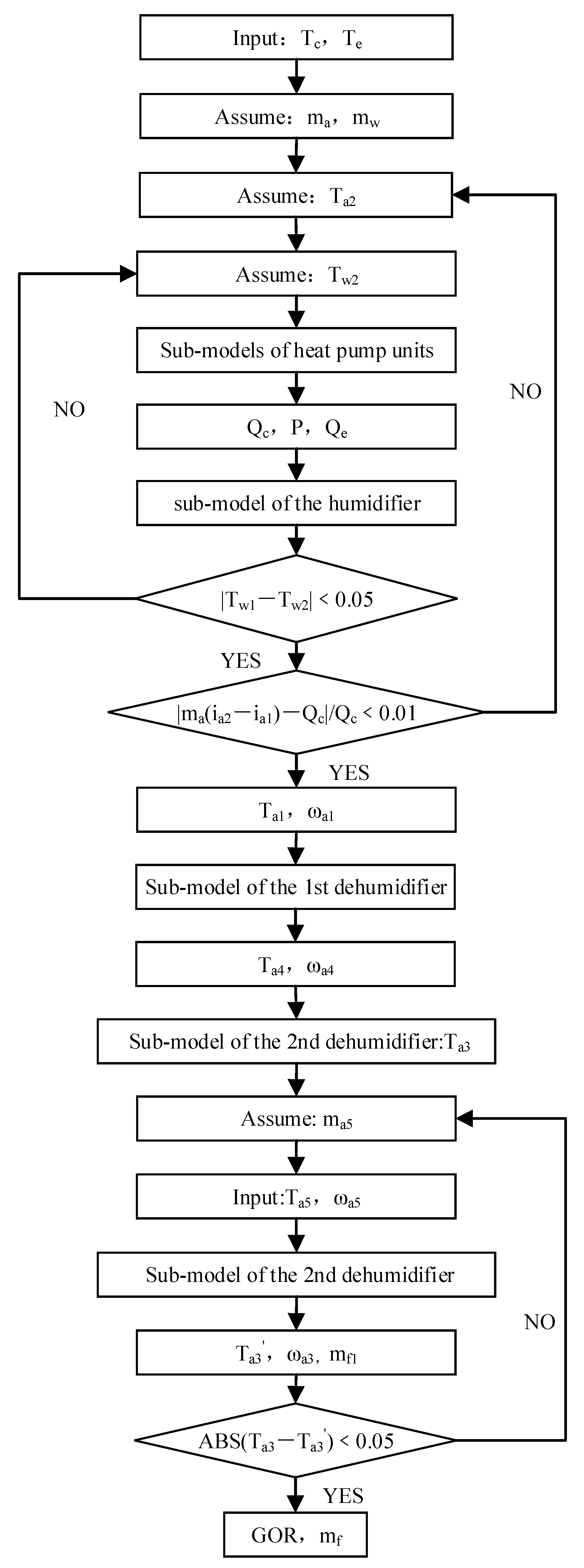
3.6. Calculation Process
3.7. Evaluation Indicators
4. Discussion
4.1. Seawater Mass Flow
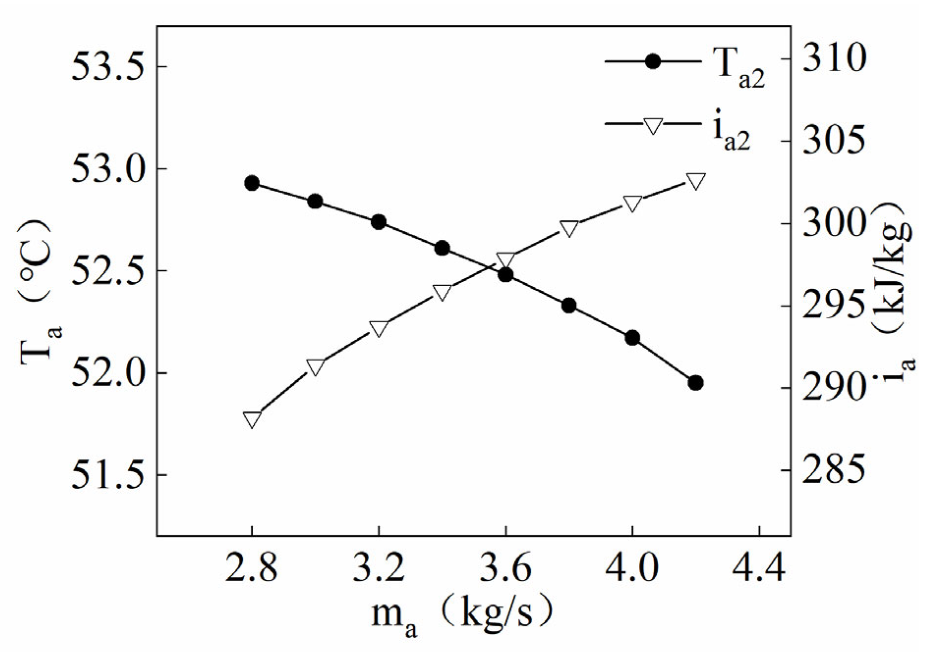
4.2. Air Mass Flow
4.3. Performance Comparison between the Current System and Other Systems
5. Study Limitations and Challenges
6. Conclusions
- (1)
- Variations in the seawater mass flow rate did not significantly improve system productivity, and there was no significant effect on system performance.
- (2)
- As the air mass flow rate increased, the overall heat and mass transfer efficiency of the system improved significantly, and the system’s productivity improved significantly.
- (3)
- The productivity of the system was 852~867 kg/h. The GOR of the system is estimated to be 4.16~4.24.
- (4)
- The system is competitive when compared with other systems.
- (5)
- The mathematical model developed in this paper provides theoretical support for the optimization of the system. The system is a closed system, and the field of application should not be limited to desalination. The system can be tested and applied in the field of wastewater treatment.
Author Contributions
Funding
Conflicts of Interest
Nomenclature
| mc | Mass flow rate of the refrigerant liquid, kg/s |
| mk | Mass flow rate of the refrigerant vapor, kg/s |
| ik | Specific enthalpy of the refrigerant vapor, J/kg |
| ic | Specific enthalpy of the refrigerant liquid, J/kg |
| Qc | Compressor heat exchange, W |
| Qe | Compressor cooling capacity, W |
| K0 | Heat transfer coefficient of the heat exchanger coils, W/(m2·K) |
| Tk | Temperature of the refrigerant in the tube, K |
| Aw | Surface area of the heat exchanger coils, m2 |
| αc | Heat transfer coefficient of the refrigerant, W/(m2·K) |
| αw | Heat transfer coefficient of the water film, W/(m2·K) |
| Βaw | Mass transfer coefficient |
| dc | Inner diameter of the heat exchanger coils, m |
| dw | Heat exchanger coils’ outer diameter, m |
| dm | Average value of the inner–outer diameter of the heat exchanger coils, m |
| Δ | Thickness of the heat exchanger coils, m |
| Λ | Thermal conductivity of the heat exchanger coils, W/(m·K) |
| a1 | State of the air point 1 |
| a2 | State of the air point 2 |
| a3 | State of the air point 3 |
| a4 | State of the air point 4 |
| a5 | State of the air point 5 |
| a6 | State of the air point 6 |
| a7 | State of the air point 7 |
| ic1 | Enthalpy of the refrigerant entering the humidifier, kJ/kg |
| ic2 | Enthalpy of the refrigerant flowing out of the humidifier, kJ/kg |
| ic3 | Enthalpy of the refrigerant entering the second dehumidifier, kJ/kg |
| ic4 | Enthalpy of refrigerant flowing out of the second dehumidifier, kJ/kg |
| P | Power consumption of the heat pump unit, W |
| cc,1~cc,10 | Constants |
| ce,1~ce,10 | Constants |
| cp,1~cp,10 | Constants |
| Te | Evaporation temperature, K |
| Tk | Condensation temperature, K |
| Q1d,n | Heat exchange in the internal heat exchange channel of the first dehumidifier, W |
| A1d,n | Heat transfer area of the heat transfer channel inside the first dehumidifier, m2 |
| ∆T1d,n | Temperature difference in the heat exchange channels inside the first dehumidifier, K |
| K1d,n | Heat transfer coefficient of the heat transfer channels inside the first-stage dehumidifier, W/(m2·K) |
| m1d,n | Mass of freshwater flowing out of the heat exchange channel inside the first dehumidifier, kg |
| i1d,n | Enthalpy of freshwater flowing out of the heat transfer channel inside the first dehumidifier, J/kg |
| Q1d,w | Heat exchange in the external heat exchange channel of the first dehumidifier, W |
| A1d,w | Heat transfer area of the external heat transfer channel of the first dehumidifier, m2 |
| ∆T1d,w | Temperature difference between the external heat exchange channels of the first dehumidifier, K |
| K1d, w | Average heat transfer coefficient of the external heat transfer channel of the first dehumidifier, W/(m2·K) |
| m1d, w | Mass of freshwater flowing out of the external heat exchange channel of the first dehumidifier, kg |
| i1d, w | Enthalpy of freshwater flowing out of the external heat exchange channel of the first dehumidifier, J/kg |
| C | Specific heat of the air |
| αl | Heat transfer coefficient between the cold fluid and the heat exchange surface |
| αr | Heat transfer coefficient between the thermal fluid and the heat exchange surface |
| ηl | Cold fluid channel efficiency |
| ηr | Thermal fluid path efficiency |
| Al | Heat transfer area of cold fluid channels |
| Ar | Heat transfer area of thermal fluid channels |
| cp | Specific heat at a constant pressure, kJ/(kg ·K) |
| λ1d | Thermal conductivity, W/(kg·K) |
| Μ | Power viscosity, kg/(m·s) |
| G | Mass flow rate, kg/(m2·s) |
| J | Heat transfer factor |
| Re | Reynolds number |
| m2d | The mass of freshwater flowing out of the second dehumidifier, kg |
| i2d | Enthalpy of freshwater flowing out of the second dehumidifier, J/kg |
| W | Power consumption of the system, W |
| Mf | Mass flow rate of freshwater, kg |
References
- Ullah, I.; Rasul, M. Recent Developments in Solar Thermal Desalination Technologies: A Review. Energies 2018, 12, 119. [Google Scholar] [CrossRef]
- Dastbaz, A.; Karimi-Sabet, J.; Ahadi, H.; Amini, Y. Preparation and characterization of novel modified PVDF-HFP/GO/ODS composite hollow fiber membrane for Caspian Sea water desalination. Desalination 2017, 424, 62–73. [Google Scholar] [CrossRef]
- Chowdhury, S.; Rahaman, M.; Mazumder, M.A.J. Global mapping of seawater desalination research: A bibliometric analysis of research trends from 1980–2022. Qual. Quant. 2023, 1–22. [Google Scholar] [CrossRef]
- Liu, J.; Sun, Y.; Yv, S.; Wang, J.; Hu, K. Experimental study on a Closed-Cycle Humidification and Dehumidification System for Treating Wastewater Containing High Concentrations of Inorganic Salts and Organic Matter. Processes 2021, 9, 671. [Google Scholar] [CrossRef]
- Yıldırım, C.; Solmuş, İ. A parametric study on a humidification–dehumidification (HDH) desalination unit powered by solar air and water heaters. Energy Convers. Manag. 2014, 86, 568–575. [Google Scholar] [CrossRef]
- Kang, H.; Wang, T.; Zheng, H. Comparative analysis of regenerative and air-extraction multi-stage humidification–dehumidification desalination system using pinch technology. Desalination 2016, 385, 158–166. [Google Scholar] [CrossRef]
- Zamen, M.; Amidpour, M.; Soufari, S.M. Cost optimization of a solar humidification–dehumidification desalination unit using mathematical programming. Desalination 2009, 239, 92–99. [Google Scholar] [CrossRef]
- Sathyamurthy, R.; El-Agouz, S.A.; Nagarajan, P.K.; Subramani, J.; Arunkumar, T.; Mageshbabu, D.; Madhu, B.; Bharathwaaj, R.; Prakash, N. A review of integrating solar collectors to solar still. Renew. Sustain. Energy Rev. 2017, 77, 1069–1097. [Google Scholar] [CrossRef]
- Xu, H.; Dai, Y.J. Parameter analysis and optimization of a two-stage solar assisted heat pump desalination system based on humidification-dehumidification process. Sol. Energy 2019, 187, 185–198. [Google Scholar] [CrossRef]
- He, W.F.; Han, D.; Ji, C. Investigation on humidification dehumidification desalination system coupled with heat pump. Desalination 2018, 436, 152–160. [Google Scholar] [CrossRef]
- Wu, G.; Zheng, H.F.; Wang, F.; Chang, Z.H. Parametric study of a tandem desalination system based on humidification-dehumidification process with 3-stage heat recovery. Appl. Therm. Eng. 2017, 112, 190–200. [Google Scholar] [CrossRef]
- Lawal, D.U.; Antar, M.A.; Khalifa, A.; Zubair, S.M.; Al-Sulaiman, F. Expermental investigation of heat pump driven humidification-dehumidification desalination system for water desalination and space conditioning. Desalination 2020, 475, 114199. [Google Scholar] [CrossRef]
- Faegh, M.; Shafii, M.B. Thermal performance assessment of an evaporative condenser-based combined heat pump and humidification-dehumidification desalination system. Desalination 2020, 496, 114733. [Google Scholar] [CrossRef]
- Lawal, D.; Antar, M.; Khalifa, A.; Zubair, S.; Al-Sulaiman, F. Humidification-dehumidification desalination system operated by a heat pump, published online in Energy Conversion and Management. Energy Convers. Manag. 2018, 161, 128–140. [Google Scholar] [CrossRef]
- Saeed, D.; Abhijit, D.; Aliakbar, A. Performance analysis of a heat pump driven humidification-dehumidification desalination system. Desalination 2018, 445, 95–104. [Google Scholar]
- Zhang, Y.; Zhu, C.; Zhang, H.; Zheng, W.; You, S.; Zhen, Y. Experimental study of a humidification-dehumidification desalination system with heat pump unit. Desalination 2018, 442, 108–117. [Google Scholar] [CrossRef]
- Zhang, Y.; Zhang, H.; Zheng, W.; You, S.; Wang, Y. Optimal operating conditions of a hybrid humidification-dehumidification and heat pump desalination system with multi-objective particle swarm algorithm. Desalination 2019, 468, 114076. [Google Scholar] [CrossRef]
- Xu, H.; Zhao, Y.; Jia, T.; Dai, Y.J. Experimental investigation on a solar assisted heat pump desalination system with humidification-dehumidification. Desalination 2018, 437, 89–99. [Google Scholar] [CrossRef]
- Lawal, D.U.; Zubair, S.M.; Antar, M.A. Exergo-economic analysis of humidification-dehumidification (HDH) desalination systems driven by heat pump (HP). Desalination 2018, 443, 11–25. [Google Scholar] [CrossRef]
- He, W.F.; Yang, H.X.; Han, D. Thermodynamic analysis of a novel humidification dehumidification desalination system driven by heat pump. Energy Procedia 2019, 158, 6030–6037. [Google Scholar] [CrossRef]
- Kaunga, D.; Patel, R.; Mujtaba, I.M. Humidification-dehumidification desalination process: Performance evaluation and improvement through experimental and numerical methods. Therm. Sci. Eng. Prog. 2022, 27, 101159. [Google Scholar] [CrossRef]
- Liu, J.; Sun, Y.; Yv, S.; Wang, J.; Hu, K. Design and Experimental Study on a New Closed-Cycle Desalination System Based on Ambient Temperature. Processes 2020, 8, 1131. [Google Scholar] [CrossRef]
- Liu, Z.H.; Guan, H.Y.; Wang, G.S. Performance optimization study on an integrated solar desalination system with multi-stage evaporation/heat recovery processes. Energy 2014, 76, 1001–1010. [Google Scholar] [CrossRef]
- Behnam, P.; Shafii, M.B. Examination of a solar desalination system equipped with an air bubble column humidifier, evacuated duct collectors and thermosyphon heat pipes. Desalination 2016, 397, 30–37. [Google Scholar] [CrossRef]
- Rahimi-Ahar, Z.; Hatamipour, M.S.; Ghalavand, Y. Experimental investigation of a solar vacuum humidification-dehumidification (VHDH) desalination system. Desalination 2018, 437, 73–80. [Google Scholar] [CrossRef]
- Zubair, M.I.; Al-Sulaiman, F.A.; Antar, M.A.; Al-Dini, S.A.; Ibrahim, N.I. Performance and cost assessment of solar driven humidification dehumidification desalination system. Energy Convers. Manag. 2017, 132, 28–39. [Google Scholar] [CrossRef]
- Shafii, M.B.; Jafargholi, H.; Faegh, M. Experimental investigation of heat recovery in a humidification-dehumidification desalination system via a heat pump. Desalination 2018, 437, 81–88. [Google Scholar] [CrossRef]


| Parameters | Unit | Condition 1 | Condition 2 | Condition 3 | Condition 4 | |
|---|---|---|---|---|---|---|
| Ta2 | °C | 51.70 | 51.30 | 51.50 | 51.90 | |
| ωa2 | g/kg | 86.48 | 79.39 | 87.00 | 85.51 | |
| mw | kg/s | 8.89 | 8.89 | 9.45 | 7.78 | |
| Ma | kg/s | 3.50 | 3.80 | 3.50 | 3.50 | |
| Ta1 | °C | Exp. | 43.40 | 42.30 | 44.00 | 42.50 |
| °C | Num. | 42.90 | 41.05 | 44.10 | 42.30 | |
| % | Deviation | 1.15 | 2.96 | 0.23 | 0.47 | |
| ωa1 | g/kg | Exp. | 15.25 | 14.30 | 15.30 | 14.70 |
| g/kg | Num. | 14.80 | 14.20 | 14.80 | 14.20 | |
| % | Deviation | 2.95 | 0.70 | 3.27 | 3.40 | |
| ia1 | kJ/kg | Exp. | 83.75 | 80.10 | 84.60 | 81.46 |
| kJ/kg | Num. | 82.10 | 78.60 | 83.40 | 79.19 | |
| % | Deviation | 2.01 | 1.91 | 1.44 | 2.87 | |
| Ta4 | °C | Exp. | 20.60 | 20.20 | 20.70 | 20.10 |
| °C | Num. | 20.27 | 19.27 | 20.67 | 19.90 | |
| % | Deviation | 1.60 | 4.61 | 0.16 | 1.00 | |
| mf | g/s | Exp. | 249.30 | 245.18 | 250.81 | 247.84 |
| g/s | Num. | 250.88 | 247.72 | 252.70 | 249.59 | |
| % | Deviation | 0.63 | 1.03 | 0.75 | 0.70 |
| mw (kg/s) | ma (kg/s) | Ta5 (°C) | φa5 (%) | φa2 (%) | |
|---|---|---|---|---|---|
| Reference values | 9 | 3.6 | 20 | 65 | 95 |
| Interval | 7.5~10.5 | 2.8~4.2 |
| Researchers | Heat Source | Maximum Productivity | GOR |
|---|---|---|---|
| Xu H. et al. [9] | Solar-assisted heat pump | 20.54 kg/h | 2.42 |
| Wu G. et al. [11] | Solar | 182 kg/h | 2.65 |
| Liu Z.H. et al. [23] | Solar | 2.138 kg/(h∙m2) | 2.5 |
| Behnam P. et al. [24] | Solar | 6.275 kg/(day·m2) | - |
| Rahimi-Ahar Z. et al. [25] | Solar | 1.07 kg/(h·m2) | 3.43 |
| Zubair M.I. et al. [26] | Solar | 19,445 kg/year | 2.6 |
| Lawal D.U. et al. [14] | Heat pump | 287.8 kg/day | 4.07 |
| He W.F. et al. [19] | Heat pump | 82.12 kg/h | 5.14 |
| Shafii M.B. et al. [27] | Heat pump | 2.79 kg/h | 2.08 |
| Current study | Heat pump | 852~867 kg/h | 4.16~4.24 |
Disclaimer/Publisher’s Note: The statements, opinions and data contained in all publications are solely those of the individual author(s) and contributor(s) and not of MDPI and/or the editor(s). MDPI and/or the editor(s) disclaim responsibility for any injury to people or property resulting from any ideas, methods, instructions or products referred to in the content. |
© 2023 by the authors. Licensee MDPI, Basel, Switzerland. This article is an open access article distributed under the terms and conditions of the Creative Commons Attribution (CC BY) license (https://creativecommons.org/licenses/by/4.0/).
Share and Cite
Liu, J.; Sun, Y.; Zhang, Y.; Wang, J. Theoretical Study of a Closed-Cycle Evaporation System for Seawater Desalination. Separations 2023, 10, 319. https://doi.org/10.3390/separations10050319
Liu J, Sun Y, Zhang Y, Wang J. Theoretical Study of a Closed-Cycle Evaporation System for Seawater Desalination. Separations. 2023; 10(5):319. https://doi.org/10.3390/separations10050319
Chicago/Turabian StyleLiu, Jun, Yong Sun, Yizhu Zhang, and Jiaquan Wang. 2023. "Theoretical Study of a Closed-Cycle Evaporation System for Seawater Desalination" Separations 10, no. 5: 319. https://doi.org/10.3390/separations10050319