1. Introduction
As high-tech power machinery, gas turbines occupy an important position in industrialized fields such as power generation and propulsion [
1]. Traditional gas turbine engines usually use diffusion combustors, which have reliable performance and strong stability, but diffusion combustors are prone to producing higher NO
X emissions [
2,
3]. As air pollutant emission regulations become more stringent, premixed combustion technology has been introduced into the gas turbine industry. At the same time, the premixed combustor satisfies the basic conditions of the thermoacoustic effect. The feedback between the fluctuation of the heat release rate and the acoustics of the combustion chamber can easily cause combustion instability. The combustion instability of a gas turbine will produce strong mechanical vibration, which is accompanied by a high heat release rate and high-decibel noise, among which low-frequency mechanical oscillations will seriously damage the impeller and the inner wall of the combustion chamber [
4].
The control of the combustion instability of a gas turbine is mainly realized through active control and passive control. The core is to decouple the flame heat release rate and pressure pulsation through the addition of interference signals or changing the design of the acoustic structure. In recent years, the rapid development of plasma-assisted combustion (PAC) technology [
5,
6,
7,
8,
9,
10] has given us important insights. In 2004, Klimov et al. [
9] conducted a plasma combustion-supporting experiment, and the results showed that the addition of plasma made the propane flame burn stably without being blown out at a higher gas flow rate, and enhanced the flame blow-out limit. In 2005, Stange et al. [
11] used the dielectric barrier discharge method to conduct combustion experiments on propane and air. The experiment proved that the plasma significantly improved the propane flame shape, and the flame after ionization became more symmetrical and stable, and with the increase in the discharge power, the root of the flame extended below the nozzle, which was caused by the increase in flame propagation speed. Lee [
12] showed that AC voltage affects the lifting height of turbulent non-premixed flames. In 2013, Lacoste et al. [
13] applied nanosecond pulse discharge in the recirculation zone of a bluff body burner. The experiment found that a large number of CH and OH* radicals were observed in the V-shaped flame recirculation zone and the upstream position after plasma was added. The temperature of the zone was increased from 1500 K to 2000 K with plasma. Lacoste et al. [
14] added nanosecond pulsed plasma to the swirling premixed flame, the flame shape changed from an M shape to a V shape, and the flame structure became more compact. In 2014, Tang [
15] studied the effect of plasma on a methane premixed flame and found that plasma can enhance methane combustion. In 2015, Kim et al. [
5] studied the application of plasma in a methane premixed flame, and the results showed that plasma can assist in the control of combustion kinetics, and its effect is closely related to the flame shape. The studies show that plasma can have a certain impact on the flame structure, and strengthen the combustion in the aspects of chemical effect, temperature rise effect, and aerodynamic effect. These three effects and their mutual coupling can significantly change the reaction rate and path of chemical reactions, adjust the mode of flow (vortex structure, etc.), trigger hydraulic instability, etc. These changes happen to be related to the mechanism of thermoacoustic oscillation. Therefore, plasma has the possibility of controlling the flame heat release rate and has the potential to become a combustion thermoacoustic instability control technology.
Lacoste et al. [
16] deeply studied the flame transfer function response of C-type, V-type, and M-type flames under the action of an acoustic field, alternating electric field, and non-thermal plasma. The research results showed that in the range of 4~450 Hz, plasma and alternating electric fields have a significant impact on the heat release rate of the three types of flames; under the action of plasma and acoustic excitation, the geometry of the flame changes significantly, and its transfer function is significantly different.
In order to further verify and analyze the effect of plasma on the instability of a swirling premixed flame, an experimental system for plasma of a dielectric barrier discharge non-thermal plasma reaction device was created to act on a methane swirling flame under acoustic excitation. The pressure and heat release rate were measured simultaneously through dual microphones and photomultiplier tubes, obtaining the influence of dielectric barrier discharge plasma on the instability of a methane swirling flame under different acoustic frequencies. Based on a planar laser-induced fluorescence (PLIF) system, the flame structure capture technology was applied to measure OH radical concentration and other experimental methods were used to further analyze the mechanism of dielectric barrier discharge plasma on the stability of a swirling premixed flame.
2. Experimental Device and Test System
2.1. Experimental Device
In order to focus on the effects of plasma parameters on the flame’s acoustic response with different working conditions, the experimental system was designed to decouple the combustion from acoustic excitation, and the flame transfer function was used to describe the flame’s acoustic response, which can be used to characterize combustion instability. The influence of plasma on the flame transfer function was quantitatively analyzed, and then the effects of plasma parameters on the combustion stability of a methane swirling premixed flame were examined.
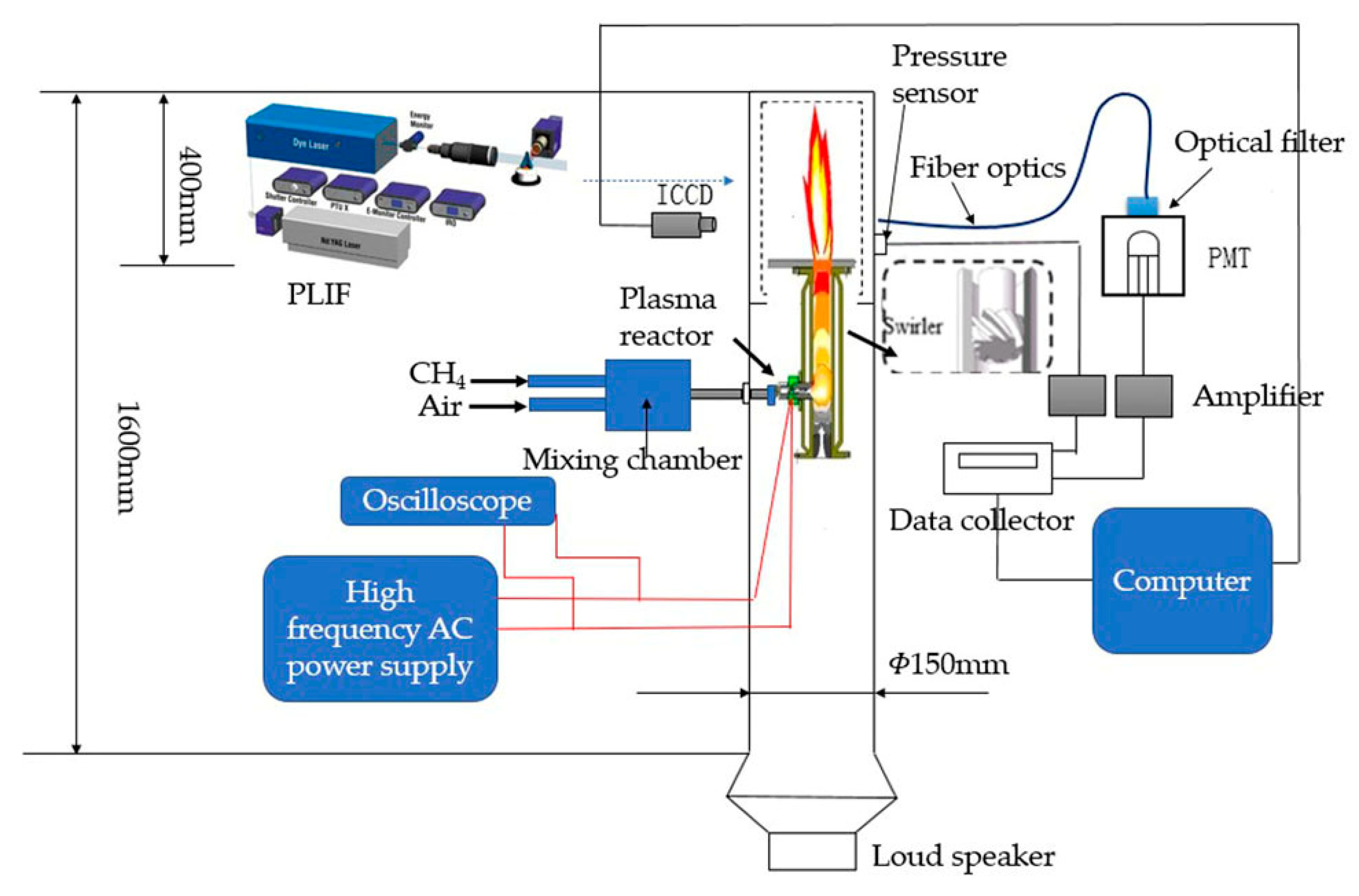
The experimental system is shown in
Figure 1, which is mainly composed of three parts: an acoustic generator, a plasma combustion device, and a test system.
The acoustic generator is composed of a round tube with an inner diameter of 150 mm and a height of 1600 mm with an opening at the top, a bottom speaker, and a horn tube. An 80 W speaker (8 inches, JBL, Los Angeles, CA, USA) is used as the source of acoustic waves, and a waveform signal generator (AFG-2225, Guwei, Taiwan) is used to generate a sine wave. The amplitude and frequency of the sine signal can be precisely controlled by a power amplifier (PRO-5 type, Accuphase, Yokohama, Japan) and a signal generator. An acoustic sine wave is formed in a circular tube with a frequency range of 80~240 Hz, and the range of acoustic pressure amplitude is 0~2200 Pa.
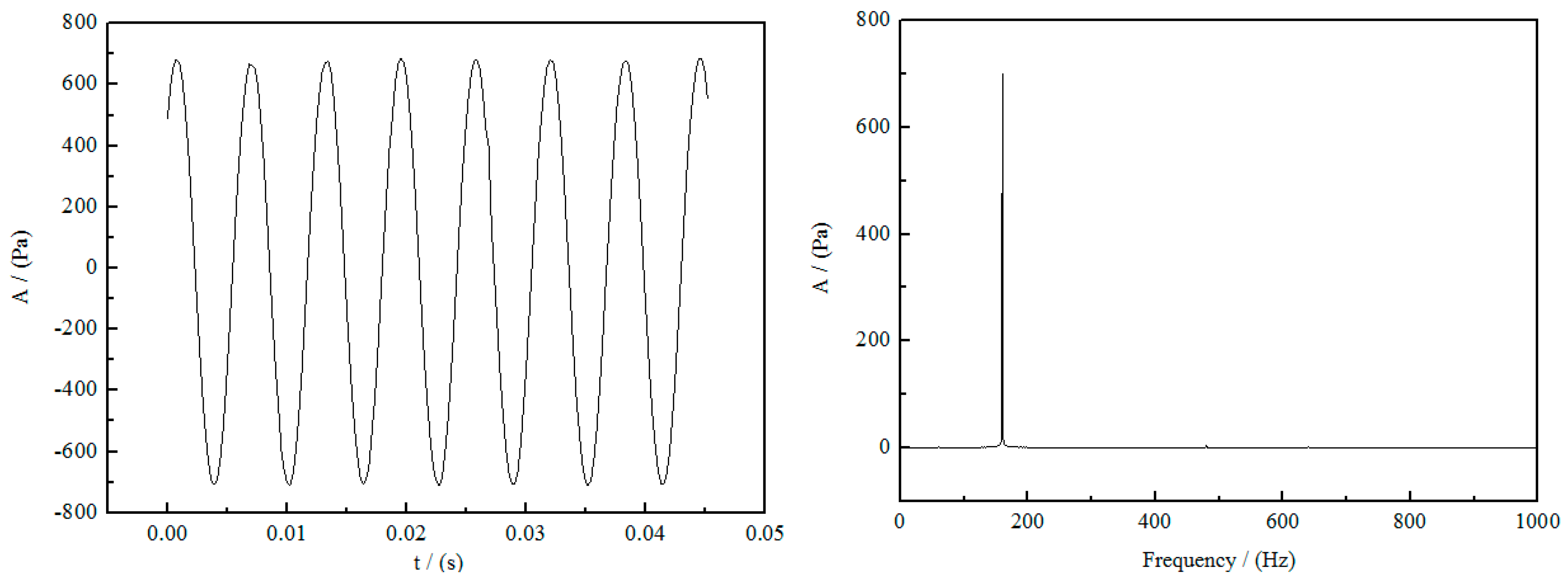
Figure 2 shows the acoustic characteristics within the tube at an acoustic frequency of 160 Hz and an acoustic pressure amplitude of 700 Pa under the excitation of the loudspeaker. The left side is the acoustic pressure signal measured by a single microphone, and the right side is the acoustic frequency obtained by Fourier transform of the acoustic pressure signal. The measured pressure signal is a regular standard sine wave.
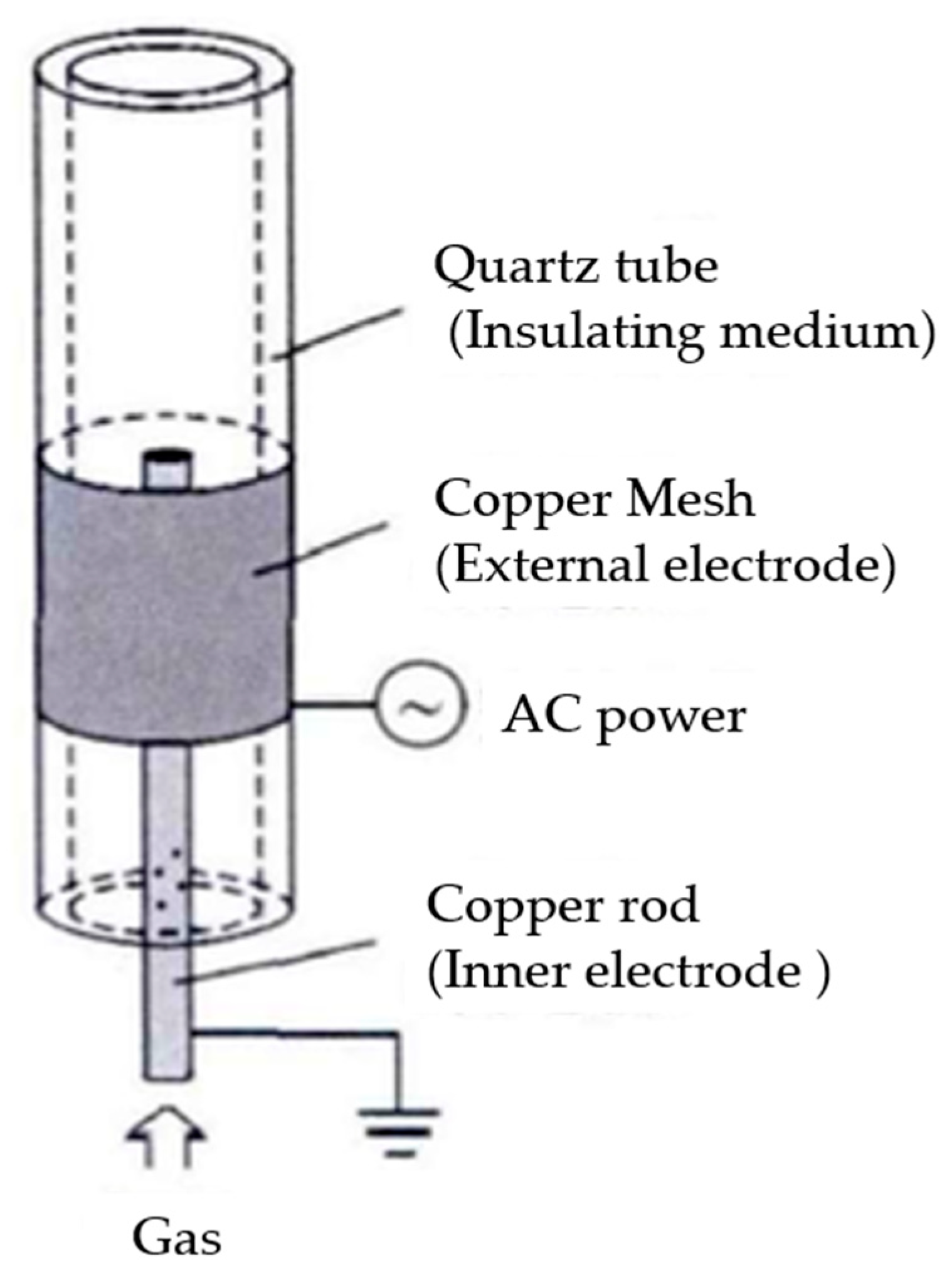
The plasma combustion device is composed of a plasma reactor and a swirling combustion chamber. The plasma reactor is a coaxial cylindrical dielectric barrier discharge reactor, as shown in
Figure 3. The ground electrode of the reactor is a solid copper rod with a diameter of 2 mm, and the blocking medium is quartz with a dielectric coefficient ε = 3.56 as an insulating sleeve. The inner diameter of the quartz tube is 14 mm, the outer diameter is 16 mm; the high-voltage electrode part is covered with a red copper mesh on the outer wall of the blocking medium, fixed with a red copper wire, and connected to the high-voltage output terminal of the plasma power supply. The low-temperature plasma power supply (CTP-2000K, China Nanjing Suman, Nanjing, China) has a center frequency range of 5~20 kHz, a maximum output power point of 10 kHz, and a maximum output voltage of 60 kV; its physical parameters are displayed by an oscilloscope (TBS-1102, Tektronix, Beaverton, OR, USA).
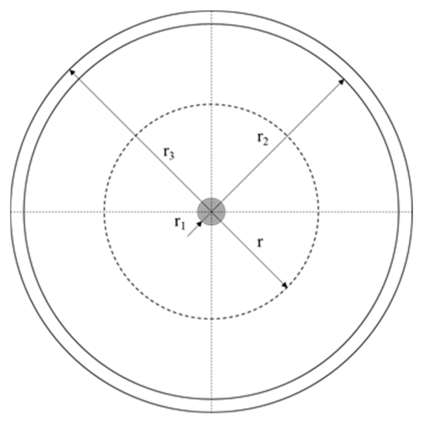
The discharge area of the coaxial cylindrical reactor is an air gap between the inner electrode and the inner wall of the quartz tube. When the premixed gas passes through the discharge area, it is ionized by a strong electric field to generate an active signal. As shown in
Figure 4, the area between the outer electrode and the inner electrode can be divided into two parts, namely the gas area from the radius r
1 of the inner electrode to the inner diameter r
2 of the quartz tube, where the dielectric constant is close to vacuum, and the inner diameter of the quartz tube r
2 to the quartz tube. The dielectric region of the tube’s outer diameter r
3, which is an insulating dielectric quartz, has a relative permittivity of εr = 3.75.
The swirl burner nozzle is located 400 mm below the top of the combustion chamber. The swirl burner is formed by adding a swirler to the jet burner nozzle. The bottom of the swirler is composed of 8 rotating guide vanes with a swirl angle of 45°, the center diameter is 8 mm, and the swirl intensity S is 0.8, as shown in
Figure 5.
2.2. Test System
The flame transfer function needs to measure the pressure signal to obtain the velocity signal. The measurement method of dual microphones is adopted. The two pressure sensors are each installed at a 5 cm distance from the combustion nozzle. The microphones are flush-mounted [
17,
18]. The wall of the chamber is 90°.
The flame transfer function can be expressed as:
where
H is the flame transfer function,
is the time-averaged heat release rate,
is the bulk velocity of the gas flow entering the combustor,
A is the velocity fluctuation of the mixture, and
and
are the corresponding amplitudes of the frequency domain signals at a forcing frequency,
, respectively. The gain is the amplitude of the flame transfer function. The frequency domain signals are converted from the time domain signals, which are acquired by the PMT and pressure transducers, respectively.
The two sets of signals are normalized to obtain a dimensionless value. The ratio of the two is the gain in the flame transfer function, which is used to characterize the degree of combustion thermoacoustic instability.
The distribution of flame OH radicals and the change in flame front morphology can be used to better analyze and understand the effects of plasma on combustion instability.
The distributions of flame OH radicals are obtained by the OH-PLIF system (Lavision, 430 nm, Bielefeld, Germany). The planar laser-induced fluorescence test system is mainly composed of a YAG laser (Q-Smart 850, Quantel, Edinburgh, UK), dye laser (Cobra-Stretch series, Sirah, Grevenbroich, Germany), and ICCD. The fluorescence signal excited by the flame OH radicals is photographed by DaVis 8.0 software, the images are single shot in the same phase, and the grayscale image obtained is post-processed to obtain the relative concentration distribution of OH radicals. The flame front image is obtained by an ICCD camera with Lavision’s narrow-band 427 nm filter. The heat release rate of the swirling flame is measured by a photomultiplier tube (R928 type, Hamamatsu, Japan) with a narrow band pass filter (315 nm, Semrock, Rochester, NY, USA).
3. Experimental Conditions
In the experiment, the premixed gas is excited by plasma, and the flame transfer function is used to quantify the combustion instability of the premixed swirling flame under acoustic excitation. The acoustic pressure and heat release rate are measured simultaneously through a microphone and a photomultiplier tube, and the effects of the dielectric barrier discharge plasma on the instability of the methane swirling flame are shown under different acoustic frequencies. Based on the planar laser-induced fluorescence measurement system, flame structure and OH radical distribution are shown and the mechanism of the dielectric barrier discharge plasma on the stability of the swirling premixed flame is further analyzed.
The experimental conditions include: a methane swirling premixed flame with an equivalence ratio of 1, a methane flow of 1 slpm, the discharge frequency of the plasma power supply is 0 kHz (no discharge), 5 kHz, 6 kHz, 7 kHz, and the discharge voltage is 0~10 kV, as shown in
Table 1.
4. Experimental Results and Analysis
4.1. The Effects of Discharge Voltage on Flame Transfer Function
Figure 6 shows the effect of the discharge voltage on the swirling premixed flame with acoustic frequencies and velocity disturbance amplitudes of 0.2. The abscissa is the acoustic frequency f, and the ordinate is the amplitude of flame transfer function. The effect of acoustic frequency and discharge voltage on combustion instability is as follows:
The different discharge frequencies are shown in
Figure 6a–c, and the amplitude of the flame transfer function varies with the discharge voltage in different acoustic frequency intervals. With the increasing of the acoustic frequency, there are many transition points about the amplitude of the flame transfer function between 80 and 240 Hz. When the acoustic frequency is less than 100 Hz, the gain gradually increases with the acoustic frequency; when the acoustic frequency is between 100 and 220 Hz, the gain in flame transfer function tends to decrease first and then increase with the acoustic frequency; when the frequency is greater than 220 Hz, the gain gradually decreases with the acoustic frequency. This is related to the different response phases of the flame upstream and downstream of the acoustic frequency [
19]. The flame response is controlled by two types of fluctuations, the first being related to azimuthal velocity perturbations generated by the swirler and convected by the flow, the second being associated with axial velocity perturbations propagating in the injector exhaust. When the discharge voltage is below 4 kV, the flame transfer function is basically the same as the gain in no electric field (0 kV); while the voltage is 6, 8, 10 kV, the flame transfer function gain decreases with the increase in voltage. At the frequency corresponding to a local minimum in the FDF (the classical flame transfer function (FTF) corresponds to the flame describing function (FDF) obtained for a fixed perturbation level) gain, it is shown that the initial and downstream regions of the flame operate in phase opposition, giving rise to heat release components which interfere destructively and yield a low level for the global heat release signal. At the frequency corresponding to a local maximum in gain, the heat release signals induced by the two types of perturbations are in phase and their combination yields a maximum level [
20].
This shows that the dielectric barrier discharge has a critical voltage. While the voltage exceeds the critical voltage, the amplitude of the flame transfer function decreases with the voltage of the plasma, which indicates that the fluctuation of the heat release rate is less susceptible to the effect of the acoustic fluctuation. It indicates that the addition of plasma exceeding the critical discharge voltage increases the ability to resist velocity disturbances, and the flame stability becomes stronger. It shows that the addition of plasma exceeding the critical discharge voltage increases the flame’s ability to resist velocity disturbances, and the flame stability becomes stronger.
As shown in
Figure 4, the radius of any cylindrical Gaussian surface in the gas zone in the circular tube is taken as
, and the voltage between the inner and outer electrodes as
. When
, the electric field intensity reaches the maximum value, and let
obtain the maximum electric field intensity.
where
is the distance between the two electrodes. When
reaches the critical value
of electric field strength, a discharge occurs between the electrodes, and the critical voltage of discharge can be obtained.
Plasma reactor r1 = 0.1 cm, r2 = 0.6 cm, the critical electric field intensity of air 30 kV/cm is brought into Equation (2), and the critical discharge voltage is 5.3 kV, which is consistent with the experiment.
4.2. The Effects of Discharge Frequency on Flame Transfer Function
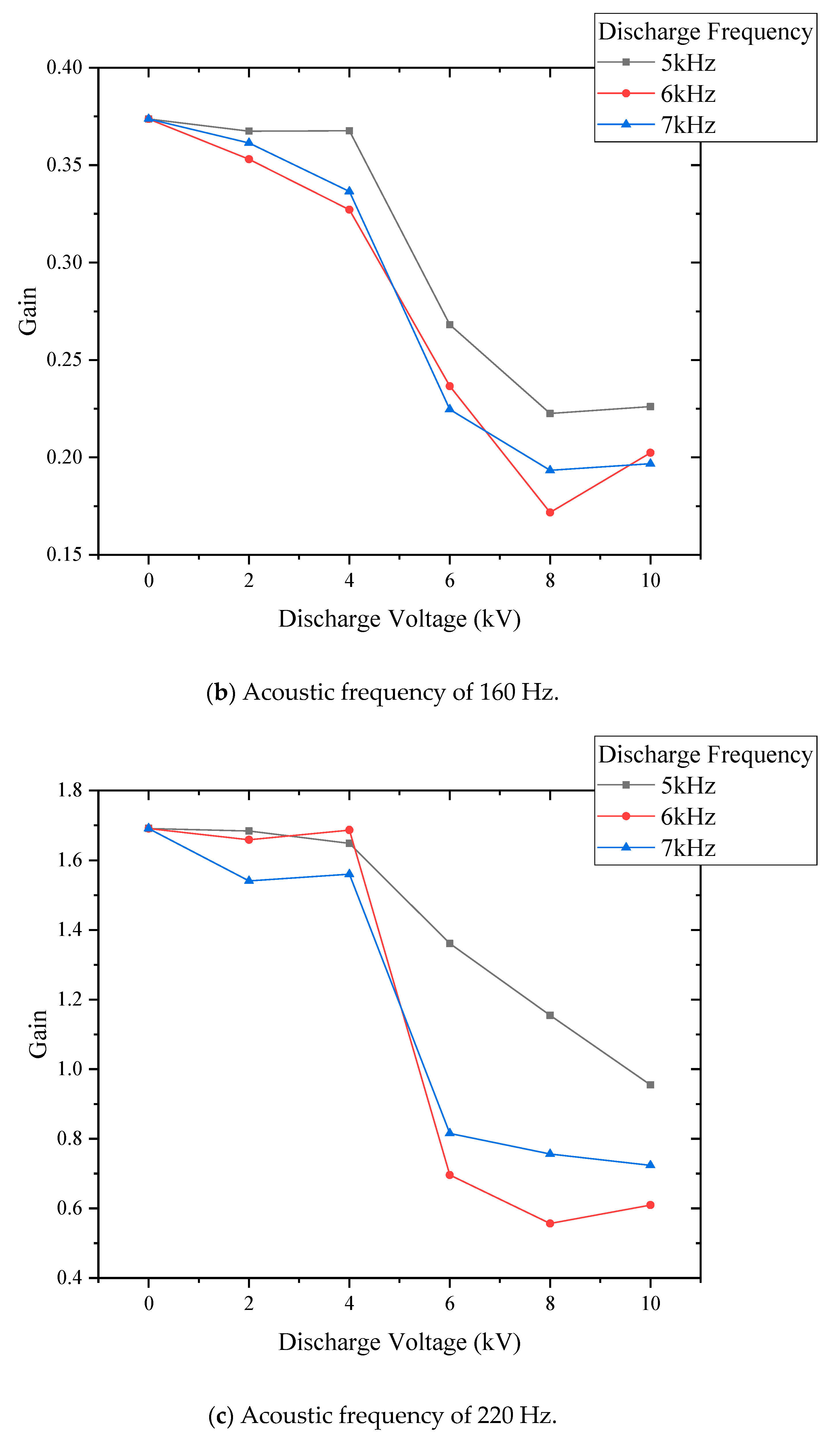
Figure 7 shows the effects of the discharge frequency on the flame transfer function when the acoustic frequency is 100 Hz, 160 Hz, and 220 Hz, and the acoustic fluctuation is 0.2.
As shown in
Figure 7, as mentioned above, when the voltage exceeds 5.3 kV, the gain in flame transfer function decreases significantly, and as the voltage increases, the gain gradually decreases. Overall, compared with the discharge frequencies of 6 kHz and 7 kHz, the discharge frequency of 5 kHz has a smaller effect on the transfer function. With the increase in discharge frequency, the flame transfer function gain also decreases to a certain extent. The higher discharge frequency may excite more active groups, which makes the flame stability stronger.
4.3. The Effects of Plasma on the Spatial Distribution of OH Radicals
In order to investigate the mechanism of the effects of plasma on the amplitude of the flame transfer function, the spatial distribution of OH radicals was obtained through the OH-PLIF system. The OH radicals can characterize the heat release rate of the combustion zone.
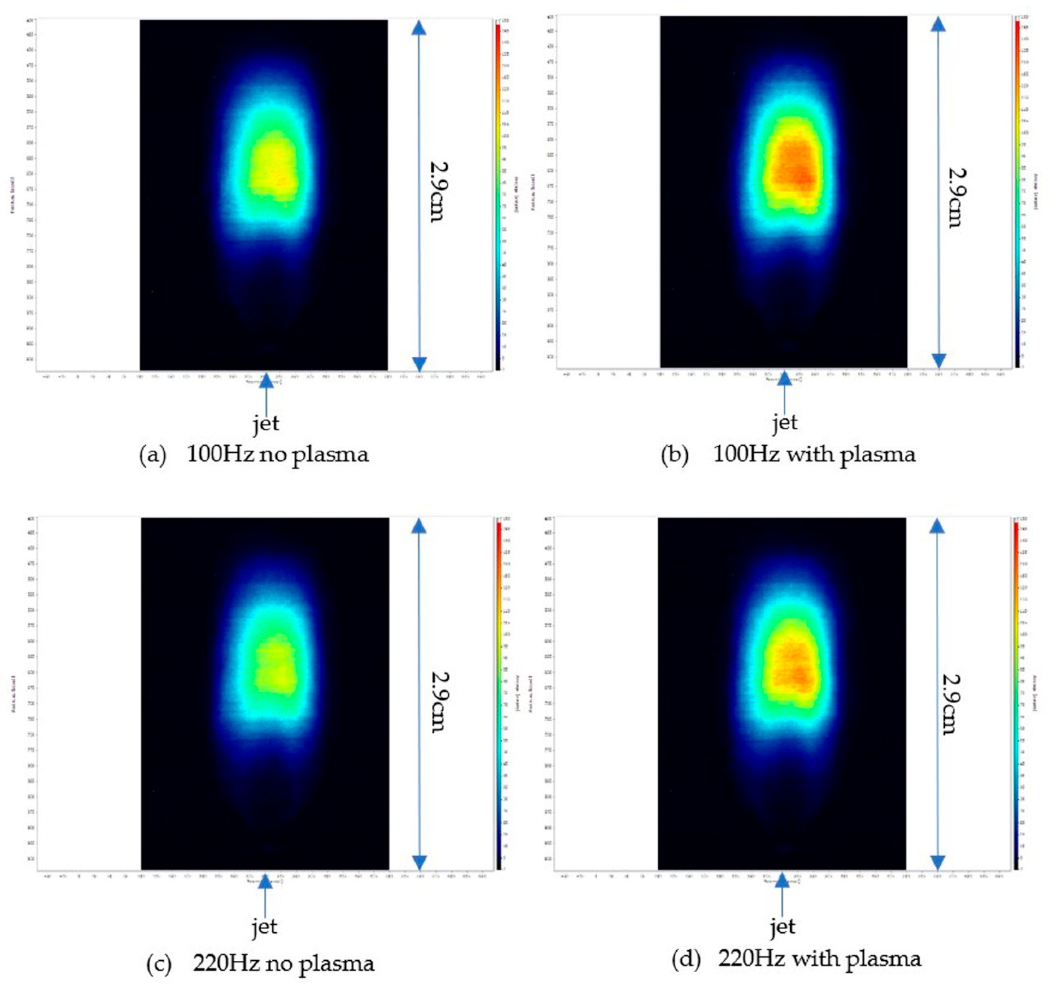
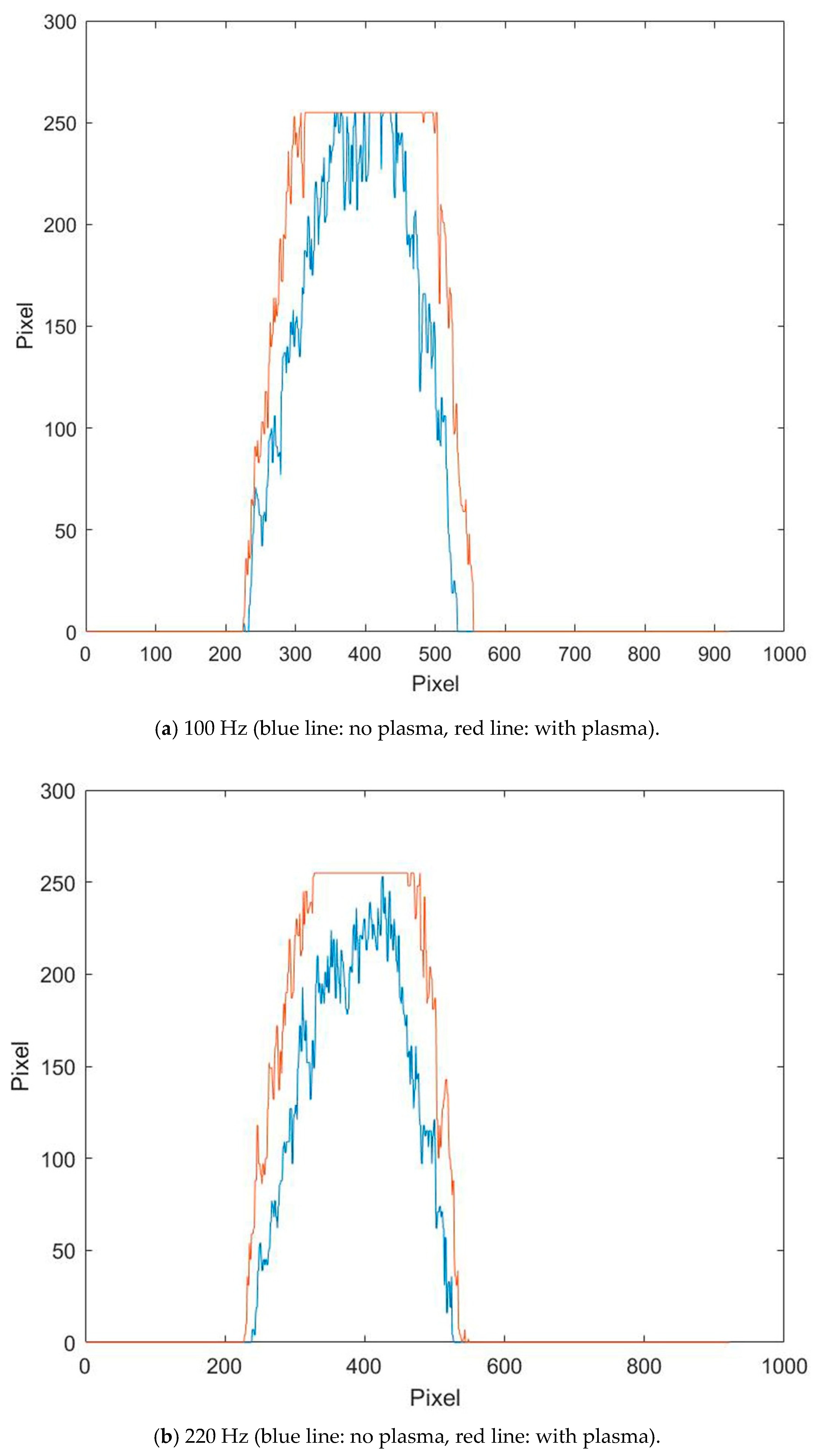
Figure 8 shows the spatial distribution of OH radicals in the swirling premixed flame when there is no plasma at a discharge voltage of 8 kV and a discharge frequency of 5 kHz under the acoustic frequencies of 100 Hz and 220 Hz.
Figure 8 and
Figure 9 show the intensity of OH under different discharge voltages. When the input voltage is 0, the intensity of OH is lower. When the input voltage increases and exceeds the critical voltage, and the effects of the plasma reactor become stronger, the intensity of OH gradually increases, and the heat release rate increases. The combustion of the methane flame becomes more complete and violent with plasma, the OH radicals in the flame also increase significantly, and the heat release rate increases.
4.4. The Effects of Plasma on the Flame Front
In the experiment, an ICCD camera with a narrowband 427 nm filter (Lavision, 430 nm) was used to photograph the flame front.
Figure 10 shows the evolution of CH* radicals with or without plasma at a discharge voltage of 8 kV and a discharge frequency of 5 kHz, and shows the flame front of the swirling flame. It can be seen from the figure that with the acoustic effects of 100 Hz, the swirling flame without plasma has a certain degree of compression on the front, and the flame length is shorter than that with plasma. The addition of plasma reduces the compression of the flame. In
Figure 10c,e, with the acoustic effects of 160 Hz and 220 Hz, a curled structure appears in the downstream area of the swirl flame without plasma. With the addition of plasma, the curl of the vortex flame surface is weakened, and the upper part of the flame front is closer to the axis. From the perspective of brightness and darkness, the addition of plasma significantly improves the flame brightness. This is due to the disappearance of the curled structure on both sides of the flame front and the reduction in the internal recirculation zone, which accelerates the transfer of premixed gas and burned gas, thereby accelerating the rate of chemical reactions and leading to an increase in the flame heat release rate.
5. Conclusions
The effects of acoustic frequency on combustion instability are seen when the acoustic frequency is less than 100 Hz, and the gain gradually increases with the acoustic frequency; when the acoustic frequency is between 100 and 220 Hz, and the gain in flame transfer function tends to decrease first and then increase with the acoustic frequency; when the frequency is greater than 220 Hz, and the gain gradually decreases with the acoustic frequency.
The effects of discharge voltage on combustion instability are seen when the discharge voltage is below 4 kV, and the flame transfer function is basically the same as the gain when the voltage is 0, when the voltage is 6 kV, 8 kV, and 10 kV, and the flame transfer function gain drops significantly, and as the voltage increases, and the gain gradually decreases. This is because when the voltage exceeds the critical voltage value of 5.3 kV, the premixed gas is ionized and the heat release rate increases significantly, thereby reducing the flame transfer function gain and enhancing flame stability.
The effects of plasma on the flame heat release rate are seen when the discharge voltage is 2 kV, 4 kV, and the flame heat release rate is basically the same as the gain when the voltage is 0, and when the voltage is 6 kV, 8 kV, and 10 kV, and the heat release rate is basically unchanged. The release rate increased significantly, and as the voltage increased, the heat release rate showed an increasing trend. This is because when the voltage is less than the critical discharge voltage of 5.3 kV, the premixed gas is not ionized, which has no significant effect on the heat release rate, while when the voltage exceeds 5.3 kV, the premixed gas is ionized to produce a large number of active groups, and the heat release rate increases significantly. Additionally, as the discharge voltage increases, the overall flame brightness increases.
In terms of the OH radicals’ concentration and flame front, which explained the mechanism of plasma changing the flame stability and heat release rate, the reasons for the effects of plasma on combustion instability and heat release rate are that plasma changes the recirculation zone inside the flame, thereby changing the compression and curling degree of the flame. The heat and mass transfer in the external recirculation zone is affected, which in turn affects the initial temperature, flame length, convection time, and other parameters of the premixed gas. As a result, the concentration of OH radicals changes, and the heat release rate changes accordingly, which ultimately changes the combustion instability of the swirling flame.
Author Contributions
Conceptualization, K.D.; methodology, K.D. and S.Z.; software, S.Z. and C.X.; validation, S.Z., J.H. and Y.Z. (Yi Zhong); formal analysis, K.D. and S.Z.; investigation, K.D. and S.Z.; resources, C.X. and J.H.; data curation, S.Z. and C.X.; writing—original draft preparation, K.D. and S.Z.; writing—review and editing, K.D.; visualization, S.Z.; supervision, Y.Z. (Yi Zhong) and Y.Z. (Yingjie Zhong); project administration, Y.Z. (Yingjie Zhong); funding acquisition, K.D. All authors have read and agreed to the published version of the manuscript.
Funding
This research was funded by Zhejiang Provincial Natural Science Foundation of China, grant number LY18E060012.
Acknowledgments
Thanks to the reviewers and editor for manuscript improvements. This research was supported by the Natural Science Foundation of Zhejiang Province under grant no. LY18E060012.
Conflicts of Interest
The authors declare no conflict of interest.
References
- Liu, W. Gas Turbine and Gas-Steam Combined Cycle; Chemical Industry Press: Hong Kong, China, 2006. [Google Scholar]
- Correa, S.M. Power generation and aeropropulsion gas turbines: From combustion science to combustion technology. Symp. (Int.) Combust. 1998, 27, 15. [Google Scholar] [CrossRef]
- Lefebvre, A.H. Gas Turbine Combustion; CRC Press: Boca Raton, FL, USA, 1984. [Google Scholar]
- Poinsot, T. Prediction and control of combustion instabilities in real engines. Proc. Combust. Inst. 2017, 36, 1–28. [Google Scholar] [CrossRef] [Green Version]
- Kim, W.; Snyder, J.; Cohen, J. Plasma assisted combustor dynamics control. Proc. Combust. Inst. 2015, 35, 3479–3486. [Google Scholar] [CrossRef]
- Bellemans, A.; Deak, N.E.; Bisetti, F. Skeletal Chemical Kinetics Mechanisms for Plasma-Assisted Combustion; American Institute of Aeronautics and Astronautics: Reston, VA, USA, 2020. [Google Scholar]
- Ju, Y.G.; Sun, W.T. Plasma assisted combustion: Dynamics and chemistry. Prog. Energy Combust. Sci. 2015, 48, 21–83. [Google Scholar] [CrossRef]
- Kim, W.; Cohen, J. Plasma-Assisted Combustor Dynamics Control at Realistic Gas Turbine Conditions. Combust. Sci. Technol. 2021, 193, 869–888. [Google Scholar] [CrossRef]
- Klimov, A.; Bityurin, V.; Kuznetsov, A. External and Internal Plasma-Assisted Combustion. In Proceedings of the 42nd AIAA Aerospace Sciences Meeting and Exhibit, Reno, NV, USA, 5–8 January 2004. [Google Scholar]
- Leonov, S.B.; Yarantsev, D.A.; Napartovich, A.P.; Kochetov, I.V. Plasma-assisted combustion of gaseous fuel in supersonic duct. IEEE Trans. Plasma Sci. 2006, 34, 2514–2525. [Google Scholar] [CrossRef]
- Stange, S.; Kim, Y.; Ferreri, V.; Rosocha, L.A.; Coates, D.M. Flame images indicating combustion enhancement by dielectric barrier discharges. IEEE Trans. Plasma Sci. 2005, 33, 316–317. [Google Scholar] [CrossRef]
- Lee, S.M.; Park, C.S.; Cha, M.S.; Chung, S.H. Effect of electric fields on the liftoff of nonpremixed turbulent jet flames. IEEE Trans. Plasma Sci. 2005, 33, 1703–1709. [Google Scholar]
- Lacoste, D.A.; Xu, D.A.; Moeck, J.P.; Laux, C.O. Dynamic response of a weakly turbulent lean-premixed flame to nanosecond repetitively pulsed discharges. Proc. Combust. Inst. 2013, 34, 3259–3266. [Google Scholar] [CrossRef]
- Lacoste, D.A.; Moeck, J.P.; Durox, D.; Laux, C.O.; Schuller, T. Effect of Nanosecond Repetitively Pulsed Discharges on the Dynamics of a Swirl-Stabilized Lean Premixed Flame. J. Eng. Gas. Turbines Power-Trans. ASME 2013, 135, 7. [Google Scholar] [CrossRef]
- Tang, Y. Study on Combustion Enhancement of Dielectric Barrier Discharge Plasma; North China Electric Power University: Beijing, China, 2014. [Google Scholar]
- Lacoste, D.A.; Xiong, Y.; Moeck, J.P.; Chung, S.H.; Roberts, W.L.; Cha, M.S. Transfer functions of laminar premixed flames subjected to forcing by acoustic waves, AC electric fields, and non-thermal plasma discharges. Proc. Combust. Inst. 2017, 36, 4183–4192. [Google Scholar] [CrossRef] [Green Version]
- Zhu, M. Dynamic Pressure Measurement; National Defense Industry Press: Beijing, China, 1983. [Google Scholar]
- Huang, D. Design of Sound Intensity Measurement and Analysis System Based on LabVIEW; Hunan University: Changsha, China, 2014. [Google Scholar]
- Deng, K.; Zhong, Y.; Wang, M.X.; Zhong, Y.J.; Luo, K.H. Effects of Acoustic Excitation on the Combustion Instability of Hydrogen-Methane Lean Premixed Swirling Flames. ACS Omega 2020, 5, 8744–8753. [Google Scholar] [CrossRef] [PubMed] [Green Version]
- Palies, P.; Durox, D.; Schuller, T.; Candel, S. The combined dynamics of swirler and turbulent premixed swirling flames. Combust. Flame 2010, 157, 1698–1717. [Google Scholar] [CrossRef]
| Publisher’s Note: MDPI stays neutral with regard to jurisdictional claims in published maps and institutional affiliations. |
© 2021 by the authors. Licensee MDPI, Basel, Switzerland. This article is an open access article distributed under the terms and conditions of the Creative Commons Attribution (CC BY) license (https://creativecommons.org/licenses/by/4.0/).


