Article

Effect of Gas Volume Fraction on the Gas-Phase Distribution in the Passage and Blade Surface of the Axial Flow Screw-Type Oil-Gas Multiphase Pump

Key Laboratory of Fluid and Power Machinery, Ministry of Education, Xihua University, Chengdu 610039, China
*
Authors to whom correspondence should be addressed.
Processes 2021, 9(5), 760; https://doi.org/10.3390/pr9050760
Submission received: 14 April 2021 / Revised: 22 April 2021 / Accepted: 23 April 2021 / Published: 26 April 2021

Abstract

:
The axial flow screw-type oil-gas multiphase pump is mainly applied to oil and gas transport in the deep sea. In the process of transporting the multiphase medium, the gas volume fraction (GVF) on the gas phase changes from time-to-time, resulting in the performance of the oil-gas multiphase pump being greatly influenced by the gas phase. This paper presents a detailed analysis of the gas-phase distribution law and the vortex distribution in the flow passages within the oil-gas multiphase pump by means of numerical calculations, supplemented by experimental verification. The results show that the gas phase is mainly concentrated in the diffuser at different GVFs, and the gas phase gathering in the diffuser becomes more significant with the increase in the GVF. The gas-phase volume fraction increases gradually from rim to hub, that is, the gas-phase gathering degree increases. The maximum gas-phase volume distribution area is mainly concentrated in the area near the hub of the diffuser inlet and the middle blade height area at the outlet of the diffuser. The flow in the impeller is relatively stable under the different GVFs, while there is a large vortex near the inlet of the diffuser near the hub, and there is a backflow phenomenon between the outlet of the diffuser and the tip clearance of the impeller. The volume fraction of the gas phase near the rim fluctuates more than that near the hub because the gas phase is squeezed by the liquid phase more violently. The research results can provide theoretical guidance for the optimal design of oil-gas multiphase pump blades.

1. Introduction

In recent years, with the increase in human demand for energy and the increasing depletion of conventional energy, many countries around the world have taken the development and utilization of marine oil and gas as an effective means to alleviate the energy shortage, while the research of key technologies for deep-sea oil and gas transmission equipment has been emphasized by various countries. Due to the complex multiphase state of deep-sea oil and gas composition, the development is difficult, so the equipment requirements are higher and the oil-gas multiphase pump has been widely used in oil and gas development because of its advantages in operation, cost and operating expenses [1,2]. As the core of multiphase transportation equipment, oil-gas multiphase pumps are the main flow and energy conversion components for the pressurization unit (one impeller and one diffuser), there are so many scholars for pressurization units, especially the impeller, respectively in hydraulic optimization, flow field analysis and the transient characteristics of a lot of research work has been done in order to improve its performance.
In terms of hydraulic optimization, Kim J [3,4] and Suh, J.-W. [5,6] conducted a multi-objective optimization of the efficiency and pressurization performance of oil-gas multiphase pumps based on the design of experiments (DOE), response surface (RSM) and numerical simulation methods, and the results of the study achieved the expected objectives and improved the pump performance. Zhang J et al. [7], based on the artificial neural network (ANN) and non-dominated sorting genetic algorithm (NSGA-II), carried out a multi-objective optimization of the impeller of the helical axial-flow multiphase pump. The study found that after optimization, pressurization and efficiency increased by about 3%. Liu M et al. [8] used the method of controlling the blade angle and orthogonal optimization to optimize the pressurization performance of the multiphase pump, and found that the pressure increased by 12.8 kPa after optimization and the pressure distribution was more uniform.
In terms of flow field analysis, Zhang J et al. [9,10,11] studied the gas-liquid two-phase flow in a multiphase pump using visualization tests and numerical simulations. The results show that as the GVF increases, the gas-liquid two-phase flow in the pump is in order of the isolated bubble flow, the bubbly flow, gas pocket flow and separated segregated gas flow. At the same time, it was found that when the inlet GVF is lower than 10% and higher than 80%, the pressurization of the compressible fluid and incompressible fluid in the multiphase pump impeller is similar. Shi Y [12] et al. studied the influence of the split impeller blade on the flow pattern of the multiphase pump, based on CFX software and the time-mean RNAS equation, and found that the gas phase gathering in the flow passage was significantly reduced compared with before the modification. Shi Guangtai et al. [13] performed the numerical calculation on the spiral axial flow oil-gas multiphase pump when the inlet GVF was 10~70% based on CFD software, and found that with the increase in the GVF, the maximum interstage turbulence intensity of the pressurization unit first decreased and then increased. Zhang Wenwu et al. [14] numerically calculated the flow field characteristics of the full flow passage of the multiphase pump, based on ANSYS CFX software and the two-fluid model, under the condition that the inlet GVF was 3~21%. The results show that the gas phase gathering in both the impeller and the diffuser occurs at the hub under different GVFs, and the gas phase gathering in the impeller becomes more obvious with the increase in the GVF. Yu Zhiyi et al. [15] analyzed the gas-liquid two-phase flow field when the GVF was 15%, based on the two-phase flow model and Reynolds time-mean NS equation, and found that the gas-liquid separation could be effectively avoided by using a small radial size difference in the flow passage of the multiphase pump.
In the transient characteristics, many scholars have done a lot of research mainly on the pressure pulsation, radial force and axial force in the pump. Zhang, J. [16,17] and Wenwu Zhang [18] studied the pressure pulsation in a multiphase pump by numerical simulation under gas-liquid two-phase conditions. The results show that the basic frequency in the impeller and the diffuser is the rotating frequency of the number of blades in the diffuser and the impeller respectively, and it is found that the basic frequency and the maximum value of pressure pulsation increase with the increase in tip clearance. Liu, X. [19] et al. studied the transient characteristics of radial force and axial force in the three-stage axial flow pump, based on the standard k-εturbulence model and the SIMPLEC algorithm, and found that the direction of axial force in the pump would change when the GVF increased, to a certain extent. Yu Zhiyi et al. [20] studied the gas-liquid two-phase flow in the impeller of a multiphase pump based on the two-fluid model and the bubble flow hypothesis. It is found that one of the main causes of gas phase gathering in the pump is the gas-phase vortex. Xu, Y et al. [21] studied the pressure transient characteristics in the spiral axial flow multiphase pump by the experimental method, and found that the pressure pulsation amplitude increased significantly in the gas-liquid two-phase condition compared with that in the pure water condition.
In addition to the above studies, many other scholars have analyzed and discussed the pump in terms of design method [22,23], energy conversion characteristics [24,25], interphase force [26,27,28] and clearance flow [29,30]. In general, for the pump many scholars in many aspects have done a lot of research work and achieved good results, but for the pump in the gas-liquid two-phase flow there is not sufficient research. At the same time, with the further exploration of the ocean by mankind, it is of great practical significance to reveal the gas-liquid two-phase flow mechanism in the multiphase pump, and to improve the efficiency of gas-liquid mixed transportation.The efficiency is the ratio of effective power to shaft power, and its equation is η = ρ g Q H M ω (ρ is fluid density, g is acceleration of gravity, Q is the flow, H is the head, M is the torque and ω is the angular velocity). So provided in this paper, based on CFX software and the SST k-ω turbulence model for the six-stage spiral axial flow oil-gas multiphase pump under the conditions of the gas-liquid two-phase study, the analysis of gas-liquid two-phase flow in the multiphase pumps phase distribution regularity and characteristics, aims to reveal its internal flow pattern, improve the efficiency of delivery, and further the service of a global strategy for the development of ocean oil and gas.

2. Prototype Pump and Numerical Setup

2.1. Prototype Pump

The self-developed axial spiral oil-gas multiphase pump is taken as the research object, and its design parameters are shown in Table 1.
Figure 1 shows the axial flow spiral oil-gas multiphase pump, which is mainly composed of the following parts: flow parts, an axial force balance device, cooling system, sealing system, bearing support mode, and structure. Figure 2 shows the physical structures of the impeller and diffuser of the oil-gas mixed multiphase pump.

2.2. Definition of Multiphase Pump Parameters

(1)
Multiphase pump flow rate (Q)
Due to the compressibility of the gas phase, the gas-phase density increases with the increase in pressure in the flow process of the multiphase medium, resulting in the volume flow rate of each phase also changing, but the total volume flow does not change. Therefore, when describing the flow rate of the oil and gas multiphase pump, the total volume flow rate of the multiphase medium is generally used.
(2)
Multiphase pump inlet gas volume fraction (GVF)
The GVF is the ratio of the volume flow rate of the gas phase to the volume flow rate of the two-phase mixture in the inlet section of the pump, characterizing the ability of the oil-gas multiphase pump to transport gas capacity, which is an important performance indicator to evaluate the oil-gas multiphase pump.
(3)
Multiphase pump head (H)
In the oil-gas multiphase pump, the bubble size is mainly determined by the rotating speed of the impeller. Under the action of a high rotating speed, the large-particle-size bubbles entering the impeller will be cut into small particle sizes at the blade head, which enhances the gas-liquid mixing. The small bubbles gradually coalesce to form large bubbles after leaving the pump cavity, so it can be assumed that the small bubbles are evenly distributed in the pump cavity.
Ignoring the heat loss in the flow process, according to the conservation of energy, then the following applies:
ρ g Q g H g + ρ l Q l H l = ρ m Q m H
where Q l = Q m ( 1 G V F ) , H l denotes the liquid-phase head of the multiphase pump, H g denotes the gas-phase head of the multiphase pump.
The law of conservation of mass is as follows:
ρ g Q g + ρ l Q l = ρ m Q m .
Assume that the mass ratio of gas and two-phase medium in the pump is χ , then the following applies:
χ = ρ g Q g ρ l Q l = ρ g Q g .
According to Equations (1) and (3), the following can be concluded:
H = ( 1 χ ) H l + χ H g .
The experimental table is generally placed horizontally, ignoring the difference in elevation between the inlet and outlet, according to Bernoulli’s equation, as follows:
H l = P 2 P 1 ρ l g + u l 2 2 u l 1 2 2 g .
Considering the flow of a multiphase medium in a multiphase pump as an isothermal process, then the following applies:
H g = P 1 ρ 1 l n P 2 P 1 + u g 2 2 u g 1 2 2 g
where ρg denotes gas-phase density, kg/m3. P1 and P2 denote the inlet and outlet pressure, Pa.ug1 and ug2 denote the gas-phase inlet and outlet flow rate, m/s.

2.3. Numerical Model of Multiphase Flow

The paper adopted CFX to perform the multiphase flow simulation. The whole computation domain is divided into eight domains, i.e., the suction chamber, six pressurization units and an extruding chamber, as shown in Figure 3. The rotating walls were set as no-slip walls. A transient rotor-stator sliding interface was used between the rotor and stator domains.
The two-phase flow was modeled by using the homogeneous model. This model assumes different fluids share the same flow field to reduce the computational load and increase the numerical stability. The standard k-ε turbulence model cannot capture the shear stress flow near the high-curvature impeller well. Therefore, a k-ω-based SST turbulence model, with automatic wall function and curvature correction (SST-CC), was adopted for high-accuracy boundary layer simulations. This model uses the Wilcox k-ω model in near-wall regions, and the standard k-ε turbulence model in the fully turbulent region where the impact of the wall is negligible. The correctness of the transition between the two models is guaranteed by the automatic near-wall treatment. Curvature correction takes the bucket curvature and runner rotation into account. The continuity and momentum equations discretely use a high-resolution scheme with the physical advection terms weighted by a gradient-dependent blend factor. While a second-order backward Euler scheme is used for the transient terms. On the basis of the residual curve reaching the set value, the calculation is considered to have converged when the differential pressure between the inlet and outlet in the constant calculation or the pressure in the non-constant calculation stabilizes within one period.

2.4. Mesh Independence Validation

The two-phase flow in the pressurization unit is studied. The suction chamber provides a certain velocity circular rector for the inlet of the head pressurization unit, and the pressure extruding chamber is to reduce the influence of the outlet flow pattern on the flow in the pressurization unit. Therefore, ICEM was used to divide the unstructured grid between the suction chamber and the extruding chamber. The two-phase flow in the pressurization unit is the research focus, so the impeller and diffuser are divided into structural grids, and the blade surface is densified by O-topology to control the Y+ value on the blade surface, so as to reduce the influence of the grid on the flow calculation and improve the solution accuracy.
The computed region grid is shown in Figure 4.
In order to ensure that the overall quality of the currently selected grid meets the actual calculation requirements, the change law of the hydraulic performance of the multiphase pump, under different grid numbers, is analyzed. Table 2 shows the hydraulic performance of the multiphase pump corresponding to the three grid numbers under the pure water condition. It can be seen from Table 2 that the head and efficiency of the mixed transport pump increase with the increase in the grid number, but the degree of increase decreases gradually. In the case of the third grid number, the fluctuation in efficiency is less than 0.1%, but it increases the amount of the calculation. After comprehensive consideration of the calculation time and the reliability of the calculation results, the second grid is chosen. The number of grids in the suction chamber, impeller, diffuser, and extruding chamber used for the numerical calculation in this study is 404,000, 576,000, 514,000 and 172,000, respectively. The total number of grids is 6.602 million, and the Y + values on the blade surface of the final selected grids are distributed between 1 and 80.

3. Experimental Test

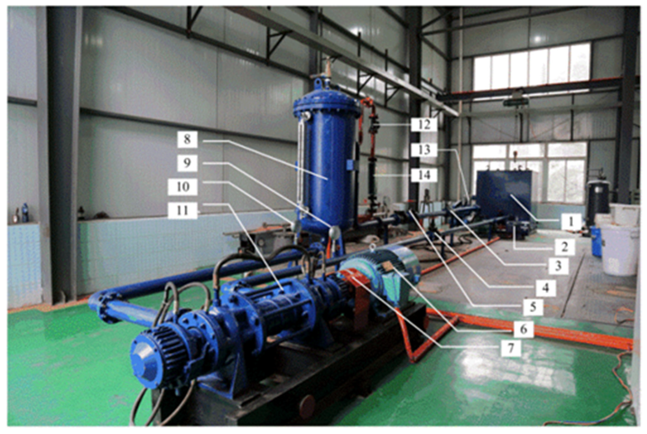
3.1. Experimental Test System for the Multiphase Pump

The experimental test system for the multiphase pump included the motor, multiphase pump, gas-liquid mixing tank, lubrication system, cooling system, control system, water supply system, gas supply system, test system, etc. The experimental system for the multiphase pump is shown in Figure 5.
In this test system, the main performance indexes of the equipment are as follows:
Motor: variable frequency speed-regulating motor, 75 kW;
Gas-liquid mixing tank: diameter 1000 mm × height 2000 mm, end face with spherical seal head, pressure resistance 5 MPa;
Experimental control system: the control of liquid flow, gas flow, inlet liquid pressure, inlet gas pressure, pump inlet and outlet pressure, rotating speed, etc.;
Precision pressure gauge: 0–5 MPa, 0.2 MPa;
Gate valve: 5 MPa, DN = 100 mm;
Check valve: 5 MPa, DN = 100 mm;
Flow meter: 14–200 m3/h, 1.5 m3/h;
Air compressor: 200 m3/h.
Table 3 shows the precision of the main equipment in this test system.

3.2. Comparison of the Experimental Results and Numerical Results

In order to verify the reliability of the numerical results, the numerical results are compared with the experimental results under the same conditions. Figure 6 shows the comparison results, Figure 6 also shows the experimental results and numerical results of six compression stages, and it can be seen that the change tendencies in the numerical results and the experimental results are consistent, and the head and the efficiency of the optimal points of relative error are 4.1% and 4.1%, respectively. The maximum relative error of the head and the efficiency is within 5%, and this shows that the results of the numerical calculation are reliable.

4. Result Analysis

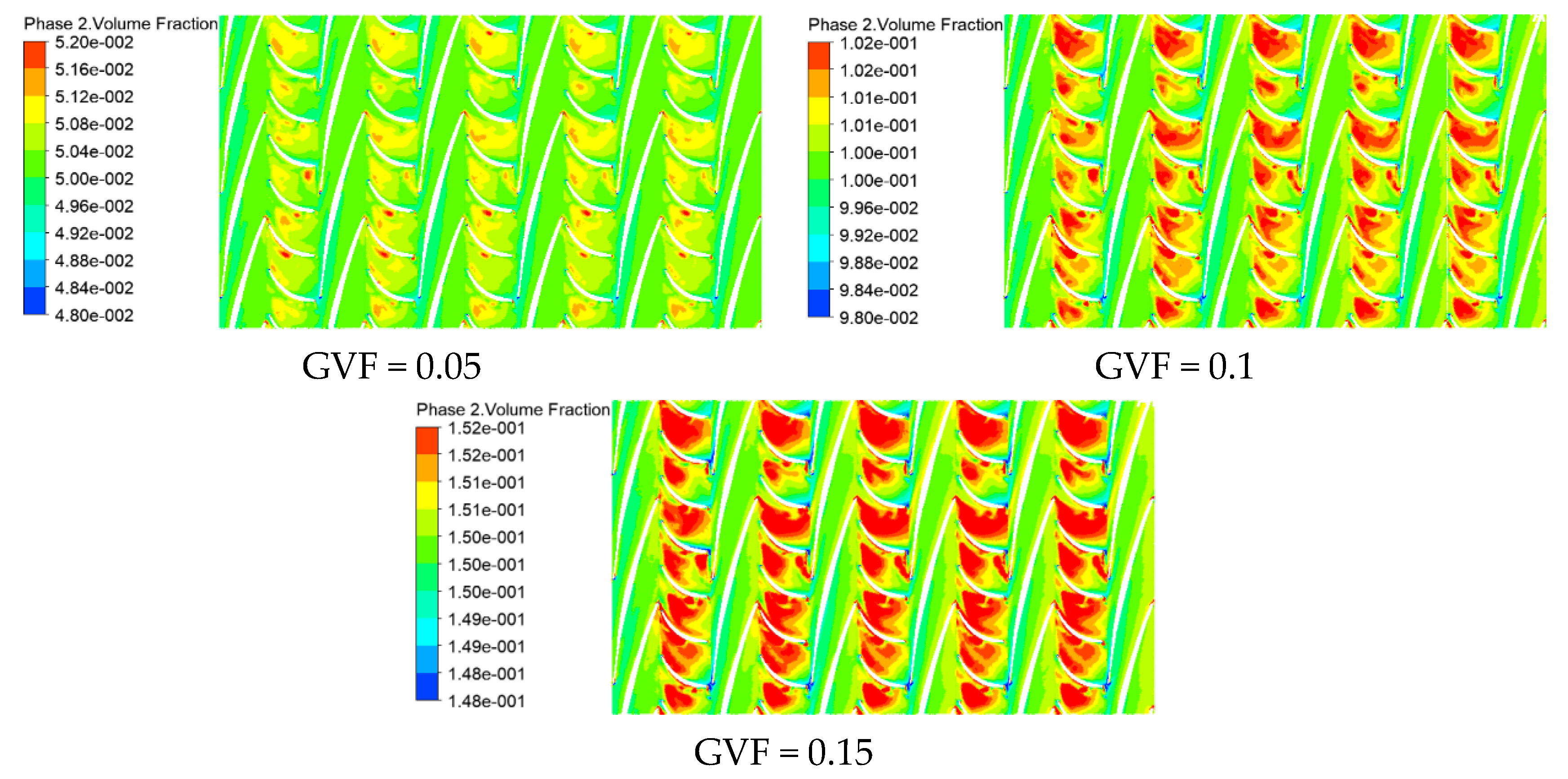
4.1. Effect of GVF on the Gas-Liquid Two-Phase Distribution in the Multiphase Pump

Figure 7 is the nephogram of the gas-phase volume distribution in the pressurization unit at 0.2 times the height of the blade at different GVFs under design conditions, and 0.2 times the height of the blade is close to the hub of the impeller. It can be seen from Figure 7 that the gas phase is mainly concentrated in the diffuser at all stages under different GVFs, and the gas phase gathering in the diffuser becomes more significant with the increase in the GVF. It can also be seen that at a low GVF, the gas phase is mainly gathered in the inlet area of the diffuser, and with the increase in the GVF, the gas phase gradually fills the entire flow passage of the diffuser. It can be seen that the GVF has a great influence on the gas-phase distribution at the hub of the diffuser.
Figure 8 is the nephogram of the gas-phase volume distribution in the pressurization unit at 0.5 times the height of the blade at different GVFs under design conditions, and 0.5 times the height of the blade is the middle position from the hub of the impeller to the rim. As can be seen from Figure 8, with the increase in the GVF, the maximum gas-phase volume distribution area in each pressurization unit gradually increases, and the maximum gas-phase volume distribution area is also concentrated in the diffuser as at 0.2 times the blade height. However, unlike the 0.2 times the blade height, the maximum gas-phase volume distribution area at 0.2 times the blade height gradually moves from the inlet of the diffuser to the outlet of the diffuser as the GVF increases, while the maximum gas-phase volume distribution area at 0.5 times the blade height gradually moves from the outlet of the diffuser to the inlet of the diffuser as the GVF increases, and the two change patterns are just opposite.
Figure 9 is the nephogram of the gas-phase volume distribution in the pressurization unit at 0.8 times the height of the blade at different GVFs under design conditions, and 0.8 times the height of the blade is the position close to the edge of the impeller. It can be seen from Figure 9 that the maximum gas volume fraction in the impeller gradually increases with the increase in the GVF. However, compared with 0.2 times the blade height and 0.5 times the blade height, the area where the maximum gas volume fraction concentrates with the increase in the GVF is relatively small. It can also be seen that the low GVF region is mainly in the impeller and diffuser at different GVFs, and the low GVF region is mainly concentrated in the dynamic impeller outlet region, near the suction surface of the diffuser blades, and in the bladeless area between the impeller and diffuser. The highest gas volume distribution area is mainly concentrated near the pressure surface of the outlet blade of the diffuser, and it gradually moves towards the inlet of the diffuser with the increase in the GVF. It is also evident that with the increase in the GVF, the low GVF area and the high GVF area in the impeller and the diffuser gradually increase, that is, the gas-liquid separation degree gradually increases, especially in the diffuser.
It can be seen from Figure 7, Figure 8 and Figure 9 that the gas phase gradually decreases from the hub to the rim, which is mainly due to the intensified gas-liquid two-phase interaction under the action of centrifugal force during the rotating process of the impeller. The closer the impeller gets to the rim, the less gas-phase distribution and the more liquid-phase distribution. It can be seen that the gas phase and liquid phase present opposite distribution laws at different blade heights, that is, the closer the GVF is to the hub, the greater the influence of the gas-phase volume distribution law in the flow passage of the impeller of the multiphase pump.
Figure 10 is the nephogram of the axial gas-phase volume distribution in the pressurization unit of the oil-gas multiphase pump with different GVFs under design conditions. Because the gas distribution law in different pressurization units is similar, one of the first-stage pressurization units is selected to analyze the axial gas volume distribution in the pressurization unit. As can be seen from Figure 10, the gas-phase distribution is relatively uniform at a low GVF, and the gas phase gathering begins to appear with the increase in GVF. It can also be seen that the greater the gas-phase volume fraction from the rim to the hub, the greater the degree of gas gathering. The maximum gas volume distribution area is mainly gathered in the area of the diffuser inlet near the hub and the middle blade height area of the diffuser outlet. The GVF area is mainly gathered in the area near the rim of the impeller outlet and the area near the rim of the inlet of the diffuser, and in the bladeless area (including the tip clearance area), which is also consistent with the above research results. This is mainly because the density of the gas phase is less than that of the liquid phase. Under the action of centrifugal force, the liquid phase with a high density is mainly gathered at the rim, while the gas phase with a low density is mainly gathered near the hub due to the squeezing action of the liquid phase. This also reflects the interaction mechanism between the gas and liquid phases in the flow through parts of the oil-gas multiphase pump.

4.2. Effect of GVF on Velocity Vector Distribution in the Multiphase Pump

Figure 11 is the axial velocity vector diagram of the pressurization unit of the oil-gas multiphase pump with different GVFs under design conditions. As can be seen from Figure 11, under different GVFs (GVF = 0.05; GVF = 0.1; GVF = 0.15), the flow in the impeller is more stable, where the flow in the diffuser is more turbulent, especially near the hub of the inlet of the diffuser there is a large vortex, and there is also a backflow phenomenon at the outlet of the diffuser. It can also be seen that under different GVFs, the backflow phenomenon exists in the tip clearance of the impeller.

4.3. Gas-Phase Distribution on the Surface of Impeller Blades in Different Pressurization Units

Select the design working condition, the medium whose GVF is equal to 10% and the liquid phase is pure water, to study the gas distribution law on the surface of the impeller blades of different pressurization units of the multiphase pump. Figure 12 shows the distribution of GVFs from the inlet to the outlet at 0.2 times the blade height of the pressure surface and suction surface of the impeller blades of different pressurization units. It can be seen from Figure 12 that at 0.2 times the height of the pressure surface of the impeller blades of different pressurization units, the position where the gas phase fluctuates the most is located at the inlet and outlet of the impeller. This is mainly due to the influence of dynamic and static interference. In addition, the gas-phase distribution of the blades on the first-stage pressurization unit in the middle of the blades is more, and the other positions are more evenly distributed. At 0.2 times the height of the suction surface of the impeller blade, the position where the gas phase fluctuates greatly, except for the inlet and outlet, is also located in the middle of the blade. It can be seen that at 0.2 times the height of the impeller blade, the gas-phase distribution in the middle of the blade is not even in the other positions of the blade.
Figure 13 shows the distribution law of the GVF from the inlet to the outlet at 0.5 times the blade height on the pressure surface and suction surface of the impeller blades of different pressurization units. It can be seen from Figure 13 that at 0.5 times the blade height of the pressure surface of the impeller blade of different pressurization units, the position with the largest gas-phase fluctuation is also located at the inlet and outlet position of the impeller, while on the blade surface, the positions with large gas-phase fluctuations on either the suction surface or the pressure surface are located near the outlet area of the blade.
Figure 14 shows the distribution law of the GVF from the inlet to the outlet at 0.8 times the blade height on the pressure surface and suction surface of the impeller blades of different pressurization units. It can be seen from Figure 14 that at 0.8 times the blade height of the pressure surface of the impeller blades of different pressurization units, the gas-phase fluctuations are significantly greater than at 0.2 times the blade height and 0.5 times the blade height, and the gas-phase fluctuations from the inlet to the outlet of the blade pressure surface become more and more. At the same time, the volume fraction of the gas phase is also smaller than the volume fraction of the inlet of the impeller (10%). At 0.8 times the blade height of the suction surface of the impeller blades of different pressurization units, the gas-phase fluctuation from the inlet to the outlet of the suction surface of the blade is always large. It can be seen that the gas phase is more severely affected by the liquid phase near the rim, resulting in a large fluctuation of the gas-phase volume fraction on the blade surface near the rim.

5. Conclusions

(1) At different GVFs, the gas phase is mainly gathered in the diffuser at the hub, and with the increase in GVF, the gas phase gathering in the diffuser becomes more significant, but the area closer to the maximum gas volume fraction gathering of the rim gradually decreases, and the low GVF area is mainly located in the impeller and the diffuser at the rim;
(2) Under the action of centrifugal force, the liquid phase with a high density mainly gathers at the edge, while the gas phase with a low density is mainly gathered near the hub due to the squeezing action of the liquid phase, resulting in a gradual increase in the volume fraction of the gas phase from the edge to the hub, that is, the greater the degree of gas phase gathering, the maximum gas-phase volume distribution area is mainly gathered in the area of the diffuser inlet near the hub and the middle blade height area of the diffuser outlet;
(3) The flow in the impeller is more stable at different GVFs, while the flow in the diffuser is more turbulent, especially near the hub of the inlet of the static impeller there is a large vortex. Moreover, backflow exists at the outlet of the diffuser and the tip clearance of the impeller;
(4) On the surface of the impeller blade of different pressurization units, the position with the largest gas-phase fluctuation is located at the inlet and outlet position of the impeller, and the position with large gas-phase fluctuation on the blade surface near the hub is located in the middle of the blade. However, at 0.5 times the height of the impeller blade, both the suction surface and pressure surface with large gas-phase fluctuations are located near the outlet area of the blade. As the gas phase is more severely affected by the liquid phase near the rim, the volume fraction of the gas phase on the blade surface near the rim fluctuates more than that near the hub.

Author Contributions

Conceptualization, methodology, software, writing—original draft, writing—review and editing, G.S.; investigation, software, writing—original draft, S.T.; writing—review and editing; investigation, software, conceptualization, X.L.; supervision, validation, H.W.; supervision, Z.S. All authors have read and agreed to the published version of the manuscript.

Funding

This work was supported by the National Key Research and Development Program (2018YFB0905200), Open Research Fund Program of State Key Laboratory of Hydroscience and Engineering (sklhse-2021-E-03), Education Department Key Project of the Sichuan province of China (Grant No. 17ZA0366), the Key Scientific Research Fund of the Xihua University of China (Grant No. Z1510417), Open Research Subject of Key Laboratory of Fluid and Power Machinery, Ministry of Education (Grant No. LTDL2020-008), the National Natural Science Foundation of China (Grant No. 51479093), the National Key Research and Development Program of China (Grant No. 2017YFC0404200), the Key Research and Development Program of Tianjin (Grant No. 18YFZCSF00310), the Key Laboratory of Fluid and Power Machinery (Xihua University), and the Ministry of Education (Grant No. SZJJ-2018-125).

Institutional Review Board Statement

Not applicable.

Informed Consent Statement

Not applicable.

Data Availability Statement

Not applicable.

Acknowledgments

This work was supported by the National Key Research and Development Program (2018YFB0905200), Open Research Fund Program of State Key Laboratory of Hydroscience and Engineering (sklhse-2021-E-03), Education Department Key Project of the Sichuan province of China (Grant No. 17ZA0366), the Key Scientific Research Fund of the Xihua University of China (Grant No.Z1510417), Open Research Subject of Key Laboratory of Fluid and Power Machinery, the Ministry of Education (Grant No. LTDL2020-008), the National Natural Science Foundation of China (Grant Nos. 52079140, 51479093), the National Key Research and Development Program of China (Grant No. 2017YFC0404200), the Key Research and Development Program of Tianjin (Grant No. 18YFZCSF00310), the Key Laboratory of Fluid and Power Machinery (Xihua University), and the Ministry of Education (Grant No. SZJJ-2018-125).

Conflicts of Interest

The authors declare no conflict of interest.

References

  1. Saadawi, H.N.H. An overview of multiphase pumping technology and its potential application for oil fields in the gulf region. In Proceedings of the International Petroleum Technology Conference (IPTC), Dubai, United Arab Emirates, 4–6 December 2007. [Google Scholar]
  2. Falcimaigne, J.; Brac, J.; Charron, Y.; Pagnier, P.; Vilagines, R. Multiphase pumping: Achievements and perspectives. Oil Gas Sci. Technol. 2002, 57, 99–107. [Google Scholar] [CrossRef] [Green Version]
  3. Kim, J.; Lee, H.; Kim, J.; Choi, Y.; Yoon, J.; Yoo, I.; Choi, W. Improvement of Hydrodynamic Performance of a Multiphase Pump Using Design of Experiment Techniques. J. Fluids Eng. 2015, 137, 1–15. [Google Scholar] [CrossRef]
  4. Kim, J.; Lee, H.; Yoon, J.; Lee, K.; Lee, Y.; Choi, Y. Multi Objective Optimization of a Multiphase Pump for Offshore Plants. ASME. In Proceedings of the Fluids Engineering Division Summer Meeting, Washington, DC, USA, 21–25 June 1998; Volume 46223, p. V01BT10A011. [Google Scholar]
  5. Suh, J.-W.; Kim, J.-W.; Choi, Y.-S.; Kim, J.-H.; Joo, W.-G.; Lee, K.-Y. Multi-Objective Optimization of the Hydrodynamic Performance of the Second Stage of a Multi-Phase Pump. Energies 2017, 10, 1334. [Google Scholar] [CrossRef] [Green Version]
  6. Suh, J.-W.; Kim, J.-H.; Choi, Y.-S.; Joo, W.-G.; Lee, K.-Y. A study on numerical optimization and performance verification of multiphase pump for offshore plant. Proc. Inst. Mech. Eng. Part A J. Power Energy 2017, 231, 382–397. [Google Scholar] [CrossRef]
  7. Zhang, J.; Zhu, H.; Yang, C.; Li, Y.; Wei, H. Multi-objective shape optimization of helico-axial multiphase pump impeller based on NSGA-II and ANN. Energy Convers. Manag. 2011, 52, 538–546. [Google Scholar] [CrossRef]
  8. Liu, M.; Tan, L.; Cao, S.L. Design method of controllable blade angle and orthogonal optimization of pressure rise for a multiphase pump. Energies 2018, 11, 1048. [Google Scholar] [CrossRef] [Green Version]
  9. Zhang, J.; Cai, S.; Zhu, H.; Zhang, Y. Experimental investigation of the flow at the entrance of a rotodynamic multiphase pump by visualization. J. Pet. Sci. Eng. 2015, 126, 254–261. [Google Scholar] [CrossRef]
  10. Zhang, J.; Cai, S.; Li, Y.; Zhu, H.; Zhang, Y. Visualization Study of Gas-Liquid Two-Phase Flow Patterns inside a Three-Stage Rotodynamic Multiphase Pump. Exp. Therm. Fluid Sci. 2015, 70, 125–138. [Google Scholar] [CrossRef]
  11. Zhang, J.; Cai, S.; Zhu, H.; Yang, K.; Qiang, R. Numerical Simulation of Compressible Flow Field in Three-stage Spiral Axial Flow Multiphase Pump. J. Trans. Chin. Soc. Agric. Mach. 2014, 45, 89–95. [Google Scholar]
  12. Shi, Y.; Zhu, H.; Yin, B.; Xu, R.; Zhang, J. Numerical investigation of two-phase flow characteristics in multiphase pump with split vane impellers. J. Mech. Sci. Technol. 2019, 33, 1651–1661. [Google Scholar] [CrossRef]
  13. Shi, G.; Wang, Z.; Luo, K. Analysis of Turbulence Intensity and Turbulence Dissipation Characteristics in the Pressure Unit of Oil-Gas Multiphase Pump. Eng. Therm. Energy Power 2018, 33, 115–121. [Google Scholar]
  14. Zhang, W.; Yu, Z.; Li, Y.; Cheng, X. Analysis of flow field characteristics in the whole flow passage of vanetype gas-liquid multiphase pump. Chin. J. Mech. Eng. 2019, 55, 168–174. [Google Scholar] [CrossRef] [Green Version]
  15. Yu, Z.; Cao, S.; Wang, G. Numerical calculation of gas-liquid two-phase flow in a vane-type multiphase pump. J. Eng. Thermophys. 2007, 1, 46–48. [Google Scholar]
  16. Zhang, J.; Tan, L. Energy Performance and Pressure Fluctuation of a Multiphase Pump with Different Gas Volume Fractions. Energies 2018, 11, 1216. [Google Scholar] [CrossRef] [Green Version]
  17. Zhang, J.; Fan, H.; Zhang, W.; Xie, Z. Energy Performance and Flow Characteristics of a Multiphase Pump with Different Tip Clearance Sizes. Adv. Mech. Eng. 2019, 11, 1687814018823356. [Google Scholar] [CrossRef]
  18. Zhang, W.; Yu, Z.; Li, Y.; Yang, J.; Ye, Q. Numerical analysis of pressure fluctuation in a multiphase rotodynamic pump with air-water two-phase flow. OGST 2019, 74, 18. [Google Scholar] [CrossRef]
  19. Liu, X.; Hu, Q.; Shi, G.; Zeng, Y.; Wang, H. Research on transient dynamic characteristics of three-stage axial-flow multi-phase pumps influenced by gas volume fractions. Adv. Mech. Eng. 2017, 9, 1687814017737669. [Google Scholar] [CrossRef]
  20. Yu, Z.; Liu, Y. Analysis of the nonsteady flow characteristics of the gas-liquid two-phase flow of the vane-type multiphase pump. Trans. Chin. Soc. Agric. Mach. 2013, 44, 66–69. [Google Scholar]
  21. Xu, Y.; Cao, S.; Sano, T.; Wakai, T.; Reclari, M. Experimental Investigation on Transient Pressure Characteristics in a Helico-Axial Multiphase Pump. Energies 2019, 12, 461. [Google Scholar] [CrossRef] [Green Version]
  22. Zhang, Y.; Zhang, J.; Zhu, H.; Cai, S. 3D Blade Hydraulic Design Method of the Rotodynamic Multiphase Pump Impeller and Performance Research. Adv. Mech. Eng. 2014, 6, 803972. [Google Scholar] [CrossRef]
  23. Cao, S.; Peng, G.; Yu, Z. Hydrodynamic Design of Rotodynamic Pump Impeller for Multiphase Pumping by Combined Approach of Inverse Design and CFD Analysis. J. Fluids Eng. 2005, 127, 330–338. [Google Scholar] [CrossRef]
  24. Shi, G.; Wang, Z. Pressurization performance of impeller in different areas of multiphase pump. Mach. Eng. 2019, 37, 13–17. [Google Scholar]
  25. Shi, G.; Luo, K.; Liu, Z.; Wang, Z. Analysis of energy characteristics in the impeller region of spiral axial flow multiphase pump. J. Drain. Irrig. Mach. Eng. 2020, 38, 670–676. [Google Scholar]
  26. Liu, M.; Cao, S.; Cao, S. Numerical analysis for interphase forces of gas-liquid flow in a multiphase pump. Eng. Comput. 2018, 35, 2386–2402. [Google Scholar] [CrossRef]
  27. Yu, Z.; Zhu, B.; Cao, S.; Liu, Y. Effect of Virtual Mass Force on the Mixed Transport Process in a Multiphase Rotodynamic Pump. Adv. Mech. Eng. 2014, 6, 958352. [Google Scholar] [CrossRef] [Green Version]
  28. Interphase force analysis for air-water bubbly flow in a multiphase rotodynamic pump. Eng. Comput. 2015, 32, 2166–2180. [CrossRef] [Green Version]
  29. Ma, X.; Li, N. The influence of radial clearance structure on the performance of oil-gas multiphase pump. J. Xihua Univ. (Nat. Sci. Ed.) 2016, 35, 98–102. [Google Scholar]
  30. Ma, X.; Zhang, Z.; Hou, Y. Effect of axial clearance variation on the performance of multistage oil-gas multiphase pump. Fluid Mach. 2015, 43, 28–32. [Google Scholar]
Figure 1. Prototype of the axial flow spiral oil-gas multiphase pump.
Processes 09 00760 g001
Figure 2. Physical structure of the impeller and diffuser of the oil-gas multiphase pump.
Processes 09 00760 g002
Figure 3. Hydraulic model of a six-stage axial flow oil-gas multiphase pump.
Processes 09 00760 g003
Figure 4. Calculation of regional meshing.
Processes 09 00760 g004
Figure 5. The multiphase pump test bench. 1. Water tank; 2. Water supply pump; 3. Flow meter; 4. Outlet valve; 5. Inlet valve; 6. The motor; 7. Torque meter; 8. Gas-liquid mixing tank; 9. Outlet pressure gauge; 10. Inlet pressure gauge; 11. Multiphase pump; 12. check valve; 13. gas compressor; 14. gas flowmeter.
Processes 09 00760 g005
Figure 6. Comparison of the experimental and numerical results.
Processes 09 00760 g006
Figure 7. The gas-phase volume distribution in the pressurization unit at 0.2 times the height of the blade at different GVFs.
Processes 09 00760 g007
Figure 8. The gas-phase volume distribution in the pressurization unit at 0.5 times the height of the blade at different GVFs.
Processes 09 00760 g008
Figure 9. The gas-phase volume distribution in the pressurization unit at 0.8 times the height of the blade at different GVFs.
Processes 09 00760 g009
Figure 10. The axial gas-phase volume distribution in the pressurization unit with different GVFs.
Processes 09 00760 g010
Figure 11. Velocity vector distribution law in the multiphase pump under different GVFs.
Processes 09 00760 g011
Figure 12. The distribution law of the GVF from the inlet to the outlet at the height of 0.2 times the blade height.
Processes 09 00760 g012
Figure 13. The distribution law of the GVF from the inlet to the outlet at the height of 0.5 times the blade height.
Processes 09 00760 g013
Figure 14. The distribution law of the GVF from the inlet to the outlet at the height of 0.8 times the blade height.
Processes 09 00760 g014
Table 1. Operating parameters of the oil-gas multiphase pump.
Flow Rate
(m3/h)
Head
(m)
Rotational Speed
(r/min)
Motor Power
(kW)
Gas Volume Fraction Range
(%)
11085300037.5 0~80%
Table 2. Grid independence verification.
MeshMesh Number/104 Head/mEfficiency/%
1498.9120.2538.30
2660.2120.9738.70
3690.8121.1238.83
Table 3. The precision of the main equipment.
Serial NumberNamePrecision
3flow meter0.5%
7torque meter0.5%
14gas flowmeter0.5%
Publisher’s Note: MDPI stays neutral with regard to jurisdictional claims in published maps and institutional affiliations.

