Article

Internal Flow and Cavitation Analysis of Scroll Oil Pump by CFD Method

College of Electromechanical Engineering, Qingdao University of Science and Technology, Qingdao 266061, China
*
Author to whom correspondence should be addressed.
Processes 2021, 9(10), 1705; https://doi.org/10.3390/pr9101705
Submission received: 31 August 2021 / Revised: 17 September 2021 / Accepted: 21 September 2021 / Published: 23 September 2021

Abstract

:
In this study, a three-dimensional model with actual clearances was established for a scroll oil pump, and the internal flow was simulated by the CFD method. The internal flows at different rotation angles were studied, and the cavitation and pressure pulsation in the scroll pump under different working conditions were analyzed. The results show that the flow in the two working chambers of the scroll pump is asymmetric due to its structural characteristics and motion mode. The high-pressure pulsation occurs in the working chamber during the end of the suction and the beginning of discharge. Under the action of high-pressure difference, there is a high-speed jet in the clearance between the orbiting and fixed scrolls, which causes a large area of cavitation downstream of the clearance. Under a low suction pressure, cavitation intensifies with the increase in rotating speed, which leads to a decrease in volumetric efficiency. It can effectively improve cavitation by increasing the suction pressure and volumetric efficiency of the pump. The pressure pulsation can be effectively improved by increasing the axial clearance and reducing the rotating speed. The method of reducing pressure pulsation by shortening the scroll profile is proposed.

1. Introduction

As a result of its technical development in recent years, scroll fluid machinery has been used widely in compressors, vacuum pumps, and other related fields.
As a positive displacement pump, the working principle of the scroll pump is similar to that of gear and vane pumps [1,2,3]. Compared with the scroll compressor, the working medium of the scroll pump is liquid, which is incompressible. To prevent the compression process in pumps, the profile of the scroll pump must be controlled within 1.5 circles. When the scroll pump is operating, the orbiting scroll makes a clockwise plane circular motion around the center of the base circle of the fixed scroll, and two suction chambers form between the contact points of the orbiting scroll and fixed scroll. With the movement of the orbiting scroll, the volume of the suction chamber increases continuously, and the liquid is sucked in. The suction chamber is closed at the rotation angle of 360°, and the internal contact point is opened immediately (shown in Figure 1a). With the movement of the orbiting scroll, the outside contact points move inward, and the volume of the inner working chamber decreases continuously (shown in Figure 1b–d). Hence, the process of pressurization and discharge of liquid is realized in scroll pumps.
Some researchers have studied different types of positive displacement pumps. Antoniak et al. and Stryczek et al. carried out visual experimental research on external gear pumps. The flow characteristics in the pump were obtained. Additionally, an optimization scheme was conceived to improve the cavitation phenomenon and working performance of the pump [4,5]. Buono et al. studied the modeling method of a gerotor pump in cavitation state by combining experimental and simulation data, which provided a reference for predicting the cavitation, power loss, and other performance parameters of the gerotor pump [6]. Chai et al. analyzed the main factors causing flow pulsation of an internal-meshing gear pump, and the direction of structural optimization was put forward [7]. Cheng et al. proposed a new cylindrical vane pump and carried out geometric theoretical derivation and simulation analysis. The results show that the internal flow field distribution and the stress of the main components are regular, and the deformation is small. With the increase in the number of vanes, the flow pulsation decreases [8]. Li et al. proposed a new cavity model with gradually varied clearance to improve the working performance of roots pump, which was studied and analyzed by CFD experiment, and the optimal clearance range was obtained [9,10]. Rundo et al. studied the influence of different structural parameters on the volumetric efficiency of vane pumps at high rotating speeds. An optimization method to improve the working performance of the pump was proposed [11].
In recent years, some scholars have conducted research on the internal flow of scroll fluid machinery. Zheng et al. studied the influence of scroll tooth wall roughness on the tangential leakage of scroll compressor by CFD [12]. Zhao et al. optimized the exhaust port of the scroll compressor, which increased the isentropic efficiency by 2.4% and reduced the unbalanced pressure difference between the two working chambers by 50% [13]. Sun et al. used the software named PumpLinx to carry out a three-dimensional transient simulation of the scroll compressor. The complex flow process in the working chamber and the transient flow characteristics of suction and exhaust were analyzed, and the suction channel was further optimized [14,15,16]. Zhang et al. carried out a transient simulation of scroll hydrogen pump for fuel cell and analyzed the effect of different clearances on volumetric efficiency. The results show that the effect of radial leakage on volumetric efficiency is more significant than that of tangential leakage [17]. Feng et al. used ADAMS to study the dynamic characteristics of its moving parts [18]. Wei et al. and Song et al. carried out a three-dimensional transient simulation of a scroll expander, used in a small ORC system, and analyzed the influence of tangential leakage flow on the gas flow in the working chamber [19,20]. Emhardt et al. analyzed the flow process of variable wall thickness scroll expander and compared the influence of different axial clearances on isentropic efficiency [21]. Yue et al. simulated the working process of single-stage and two-stage scroll vacuum pumps, respectively. Additionally, they found that compression and over-compression would lead to significant gas pressure variation and violent compression torque pulsation [22,23]. Wang et al. optimized the profile of the asynchronous suction scroll vacuum pump, established an asymmetric scroll structure with an equal volume ratio, and solved the problem of irreversible gas flow loss [24].
However, few studies have been carried out on scroll pumps. Kritmaitree et al. simulated the internal flow of scroll pumps. The results show that the pressure imbalance occurs in two symmetrical crescent-shaped working chambers. Additionally, the low-pressure region causes cavitation, which leads to the unstable operation of the pump [25,26]. Sun et al. simulated the two-dimensional unsteady flow field and cavitation of scroll pump and obtained the flow field distribution characteristics and cavitation location under different rotation angles. The results show that deep pressure pulsation occurs in the working chamber at the initial stage of liquid discharge [27].
The abovementioned studies only researched the liquid flow in scroll pumps by not considering the influence of axial clearance on volumetric efficiency. Most studies focus on the basic analyses of the flow field, but few studies analyze the detailed performance of scroll pumps. In this paper, a three-dimensional fluid model of scroll pumps with all leakage gaps was established. Additionally, the 3D transient flow of the scroll pump was simulated by dynamic grid technology, and the internal flow characteristics of the working process of the scroll pump were obtained. The performance and cavitation of the pump, influenced by rotating speed, suction pressure, the radius of rotation, and other parameters, were studied. The influence of rotating speed, axial clearance, and the profile length on pressure pulsation was further analyzed.

2. Calculation Models

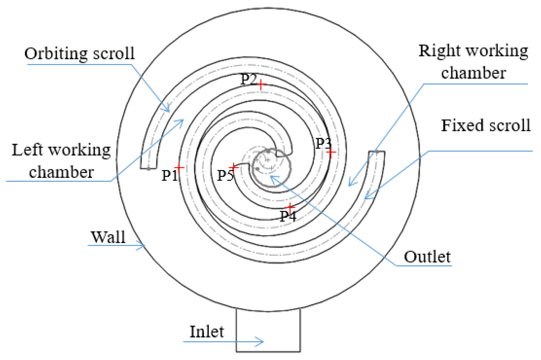
2.1. Geometric Models

Profiles are the foundation of scroll machinery, and the involute of a circle is the commonly used profile, which was used as the profile of scroll oil pump in this paper. The involute equation of the circle is as follows [28]:
{ x = a ( cos ϕ + ϕ sin ϕ ) y = a ( sin ϕ ϕ cos ϕ )
where a is the radius of the base circle, and ϕ is the involute angle.
As there is the thickness of the working walls, the inner and outer involutes are needed. The inner and outer involute equations are as follows:
{ x i = a [ cos ( ϕ α ) + ϕ sin ( ϕ α ) ] y i = a [ sin ( ϕ α ) ϕ cos ( ϕ α ) ]
{ x o = a [ cos ( ϕ + α ) + ϕ sin ( ϕ + α ) ] y o = a [ sin ( ϕ + α ) ϕ cos ( ϕ + α ) ]
where α is the angle between the axis and the generating line at the starting point of the inside and outside involutes.
The relationship between the parameters α and wall thickness t is as follows:
t = 2 a α
The parameter values of the scroll oil pump used in this paper are shown in Table 1. The geometric model used in this paper is shown in Figure 2. To analyze the pressure changes in the working chamber by the CFD method, we set up five monitoring points (P1–P5) close to the wall of the fixed scroll plate, and the interval between the two monitoring points was 90°.

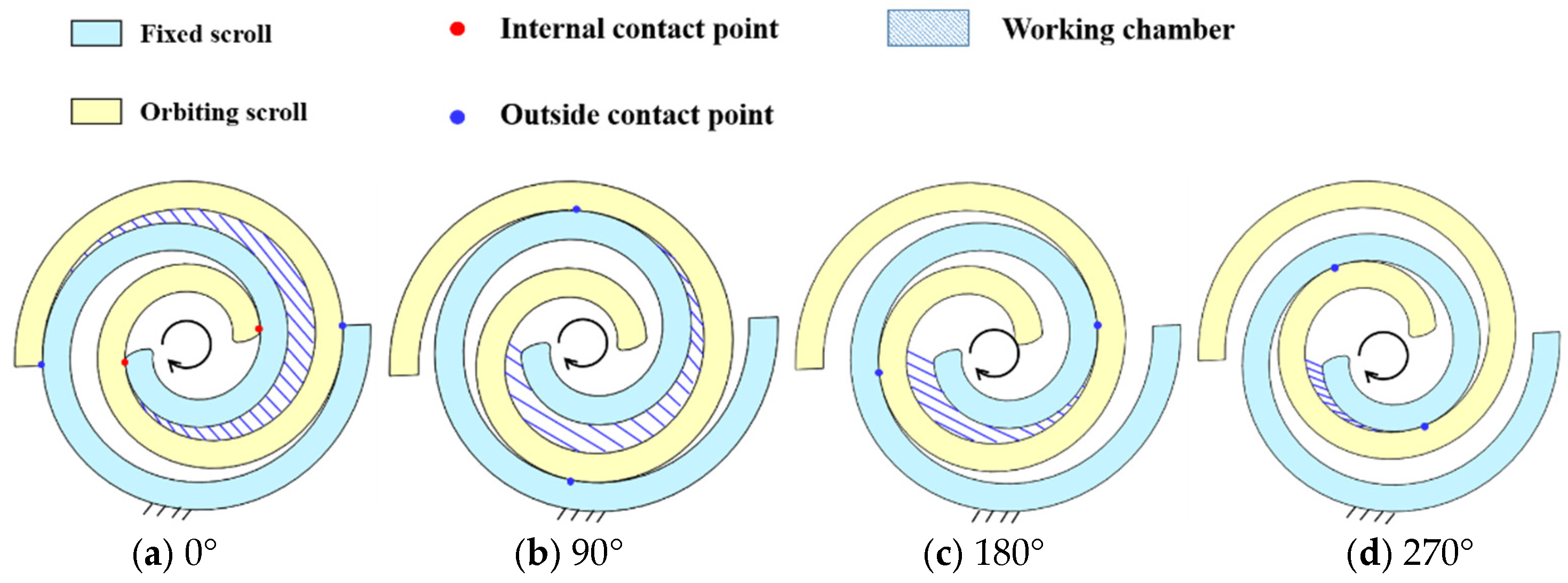
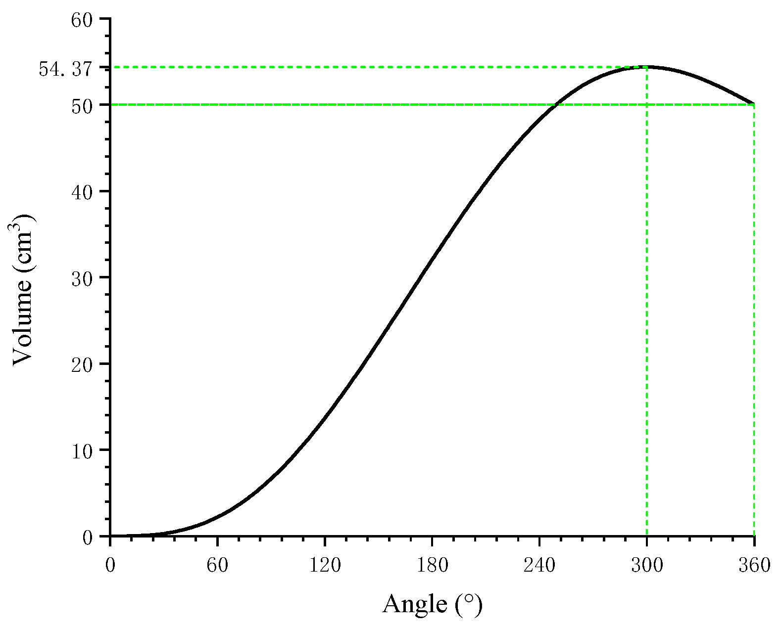
2.2. Volume Change Characteristics

The working chamber volume of the scroll pump changes with the rotation angle θ . Equation (5) shows the relationship between the rotation angle and working chamber volume.
V ( θ ) = a ρ H [ θ ( 2 ϕ E θ π ) 2 ( ϕ E π + α ) sin θ ( π 2 α ) sin 2 θ + 2 ( 1 cos θ ) ]
where ϕ E is the final development angle of involute.
It can be seen from Figure 3 that the maximum volume of the working chamber is reached before the suction chamber is closed (rotation angle 0°). For the model of this paper, the volume arrives at the largest value at the rotation angle of 300°, and the difference between the maximum volume and the volume of the closed chamber is about 8.7%. Hence, some oil would spit out before the working chamber is closed. If this part of oil cannot be discharged in time, the pressure pulsation would appear in the working chamber due to the incompressibility of oil.

3. Methodology

3.1. Cavitation Mathematical Models

The cavitation model is a full cavitation model, which was first studied by Singhal et al. [29]. The compressibility of liquid and the evaporation and condensation process of steam were considered in this model. It can have better convergence and stability by combining the unique grid technology and discrete format in the software. The vapor distribution of cavitation is described by the following equation:
t Ω ( t ) ρ m f V d Ω + σ ρ m ( ( ν ν σ ) n ) f V d σ = σ { D f + μ t σ f } ( f V n ) d Ω + Ω ( R e R c ) d Ω
where ρ m is the density of the mixture, f V is the mass fraction of the vapor, Ω is the control volume, ν is the velocity vector, n is the normal vector of the point on the surface, σ is the surface of the control volume, D f is the diffusivity of vapor, μ t is the turbulent viscosity, σ f is the is turbulent Schmidt number, R e is the vapor generation rate, and R c is the vapor condensation rate.
Using the standard viscous flow (Navier–Stokes) equation, the relationship between fluid density ρ m and vapor mass fraction can be written as
1 ρ m = f v ρ v + f g ρ g + 1 f v f g ρ l
The expressions of R e and R c are as follows:
R e = C e ( 1 f v f g ) ρ v ρ l σ l 2 K ( p p v ) 3 ρ l
R c = C c f v ρ v ρ l σ l 2 K ( p p v ) 3 ρ l
where p is the pressure, p v is the critical pressure of the gas phase, ρ l is the density of the liquid, f v is the mass fraction of the vapor, f g is the mass fraction of non-condensable gas, K is the turbulent kinetic energy, σ l is the surface tension, C e , C c are empirical constants, and C e = 0.02 ,   C c = 0.01 .

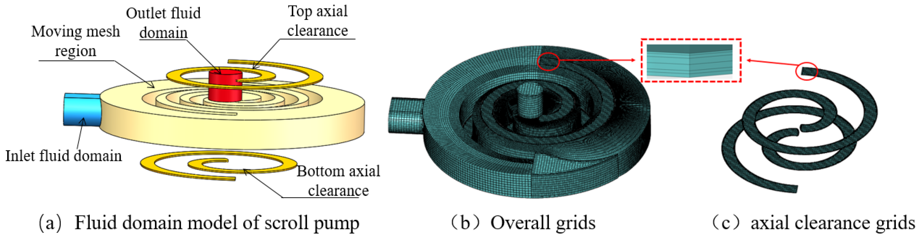
3.2. Mesh and Boundary Conditions

The fluid domain of the scroll pump was divided into the moving mesh region and the fixed mesh region. The moving mesh region was the rotation region of the orbiting and fixed scroll plates. The fixed mesh region included the inlet/outlet fluid domains and the axial clearance (shown in Figure 4a). Different mesh generation methods were used for the calculated regions. The mesh of the rotor deformation area was generated by the scroll template in the computing platform, and the other areas were generated by the general mesh generation technology (Figure 4b). The grid in the axial clearance area was densified to ensure the quality of the grid. Six layers of the grid (Figure 4c) were generated at the clearances. Additionally, the number of model grids was about 490,000. The building interface realized the data connection of each simulation region.
The working fluid was L-HM46# hydraulic oil. The boundary conditions were as follows: The oil temperature is 313 K, the density is 875 kg/m3, and the dynamic viscosity of the oil was 0.04025 Pa·s. The inlet and outlet pressures were 0.1 MPa and 10 MPa, respectively. The k-epsilon turbulent model, pressure–velocity coupling method using a SIMPLEC algorithm, and the second-order upwind discretization scheme were adopted in the numerical simulation.

3.3. Grid Independence Verification

The results of the grid independence verification are shown in Table 2. When the number of grids is 272526 and 649546, respectively, the volumetric efficiency of the scroll pump is 96.287% and 96.392%. When the number of grids is 493154, the deviation of the volumetric efficiency is 0.116% and 0.007%. Hence, the effect of the grid on the volumetric efficiency can be ignored when the number of grids is greater than 49354.

4. Result and Discussions

4.1. Flow Field Analysis

The pressure distributions in the simulation region at different rotation angles are shown in Figure 5. It can be seen that the pressure distribution is asymmetric in the whole simulation region (two crescent working chambers). The working chamber is closed at 0°. Additionally, the pressure is 0.85 MPa in the lower-left working chamber and 24.6 MPa in the upper-right working chamber. When the rotation angle is 10°, the pressure reaches 33.8 MPa in the upper-right working chamber and 22.3 MPa in the lower-left working chamber. With the movement of the orbiting scroll plate, the connection area between the working chamber and discharge chamber increases, and the pressure in the working chamber decreases. The working chamber is fully connected to the liquid discharge chamber at 30°. Hence, the pressure is stable in the value of discharge pressure.
The velocity vector distribution in the middle section of the simulation region at 0° and 180° is shown in Figure 6a,b. Figure 6c,d shows the velocity vector distribution in the axial clearances at 10°. It can be seen that there is an apparent high-speed jet phenomenon in the clearance under the action of high-pressure difference. The high-speed jet phenomenon is obviously due to the high-pressure difference at 0°, and the highest speed reaches 43.4 m/s. The liquid downstream of the clearance is affected by the high-speed leakage flow, which changes its movement direction and forms a vortex.
Figure 7 shows the volume fraction distribution of the gas phase in the pump. It can be seen that cavitation mainly occurs in the clearance and downstream areas of leakage paths. Additionally, the level of cavitation is more serious at the initial stage of the suction process (shown in Figure 7b). The opening area of the suction chamber is small, and the velocity of the leakage flow is high, which leads to the oil not being sucked in time and resulting in cavitation. With the moving of orbiting scroll plate, the suction port is fully opened, and cavitation is weakened. However, due to the disturbance of the rotation of orbiting scroll, the cavitation phenomenon is still obvious in the upper working chamber (shown in Figure 7c). The moving orbiting scroll extrudes the oil between the orbiting scroll plate and shell. Additionally, the low-pressure region is formed by the high velocity of oil, which leads to cavitation. With the movement of the orbiting scroll, the interaction between the orbiting scroll plate and the oil in the right channel produces a vortex. Hence, a large cavitation area occurs at the lower working chamber (Figure 7a,d).
Figure 8 shows the pressure of the monitoring points in the working chambers. It shows that pressure pulsation occurs in the working chamber during the end of suction and the beginning of discharge. The highest pressure reaches 39 MPa at the rotation angle of 10°, which seriously affects the stability of the pump. The volume of the suction chamber begins to decrease before the end of suction. Additionally, the area of the flow channel between the suction chamber and the inlet is small when the working chamber is about to close. Hence, the oil cannot be discharged in time and is squeezed, which causes pressure pulsation. In the early stage of the discharge of oil, the area of the flow channel between the working chamber and the discharge chamber increases slowly, which leads to its continuous compression, and then the pressure in the working chamber increases.

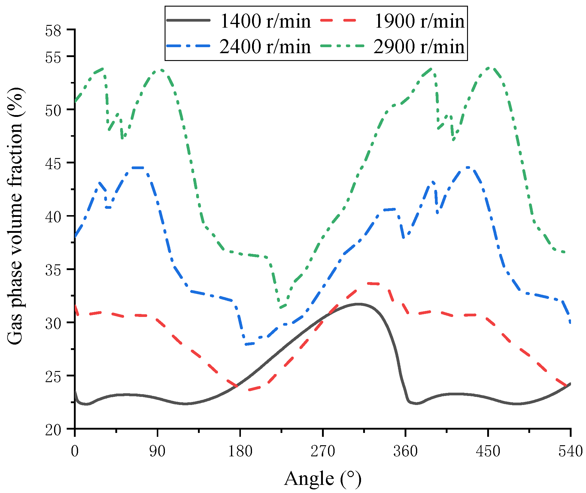
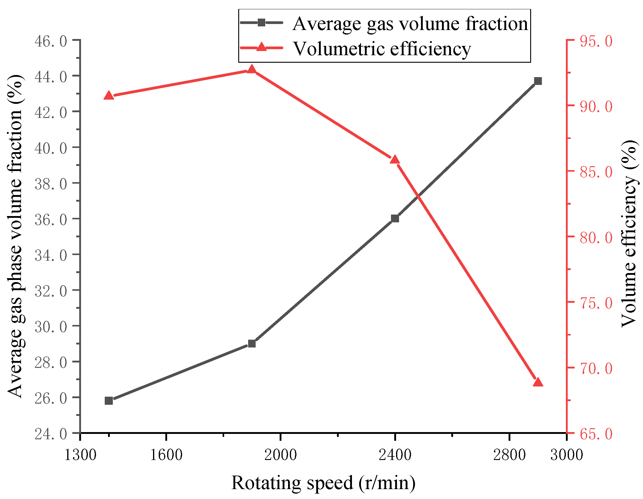
4.2. Performance and Cavitation under Different Working Conditions

Figure 9 shows the change of the gas-phase volume fraction at different rotating speeds when the inlet pressure is 0.1 MPa. The gas-phase volume fraction decreases with the decrease in rotating speed, which means that the cavitation decreases.
It can be seen from Figure 10 that serious backflow occurs at the initial stage of oil discharge at a high rotating speed. The minimum value of the instantaneous flow rate is −28 L/min at 2400 r/min. The backflow phenomenon is more severe at 2900 r/min because the high rotating speed leads to the increase in cavitation, and the oil is blocked by bubbles that prevent the inflow of oil. The backflow phenomenon leads to a decrease in volumetric efficiency. It can be seen from Figure 11 that volumetric efficiency increased with the decrease in rotating speed. The volumetric efficiency is 68.8% at 2900 r/min, but it decreased when the rotating speed decreased to 1400 r/min. The optimal rotating speed of the scroll pump used in this paper is about 1900 r/min.
Figure 12 shows the changes of the gas volume fraction under different rotation radii. When the discharge capacity is 50 mL/r, the rotating speed is 1900 r/min, and the oil suction pressure is 0.1 MPa. With the increase in rotation radius, the cavitation in the pump becomes more and more severe, and the volumetric efficiency of the pump decreases. When the rotation radius increases from 5 mm to 8 mm, the average gas volume fraction increases from 29% to 38.1%, and the volumetric efficiency decreases from 92.7% to 86.2%. Under the same discharge capacity, the larger the rotation radius is, the higher the moving velocity of the orbiting scroll, and the stronger the disturbance to the oil, so cavitation is more obvious. At the same time, with the increase in rotation radius, the length of the leakage lines of the pump becomes larger, so leakage would increase, which leads to the decline in volumetric efficiency. It can be seen from Figure 13 that when the rotation radius increases from 6 mm to 8 mm, the rate of decrease in volumetric efficiency is more significant than that when the rotation radius increases from 5 mm to 6 mm. Therefore, to ensure the performance of the scroll pump, its rotation radius should not be too large.
Figure 14 shows the variation curve of the gas-phase volume fraction under different oil suction pressure at 2900 r/min. It can be seen that with the increase in oil suction pressure, the cavitation in the working chamber is visibly improved. It can be seen from Figure 15 that when the oil suction pressure increases from 0.1 MPa to 0.25 MPa, the average gas-phase volume fraction decreases from 43.6% to 11.6%, and the volumetric efficiency of the pump increases from 68.8% to 96.4%. Therefore, the cavitation in the pump can be weakened by increasing the suction pressure at a high rotating speed.

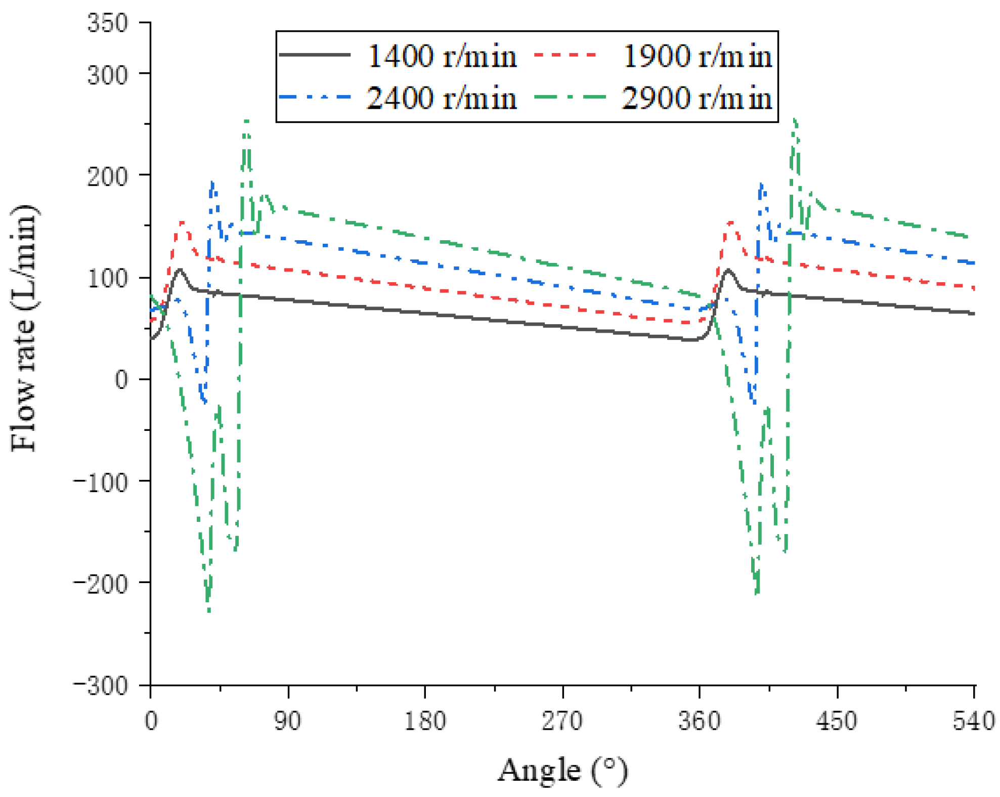
4.3. Pressure Pulsation under Different Working Conditions

Figure 16 shows the pressure of P2 (monitoring point) at different rotating speeds when the inlet pressure is 0.25 MPa, and the axial clearance is 0.05 mm. With the decrease in rotating speed, the maximum pressure of P2 decreases. With the decrease in rotating speed, the volume change rate of the working chamber with time decreases. In a specific range of the rotation angle (before the crescent-shaped working chamber is closed), the volume of the working chamber decreases slowly. Additionally, more oil is discharged with the increase in pressure. Hence, the maximum pressure of P2 decreases.
Figure 17 shows the pressure of P2 at different axial clearances when the inlet pressure is 0.25 MPa, and the rotating speed is 2900 r/min. It can be seen that with the increase in the axial clearance between the upper and lower scrolls, the maximum pressure in the working chamber visibly decreases. In the range of pressure pulsation angle, the leakage through the two axial clearances would increase, resulting in the working chamber releasing pressure in time.
It can be seen from Table 3 that the maximum pressure decreases by 19.3 MPa, and the volumetric efficiency decreases by 4.1% when the rotating speed decreases from 2900 r/min to 1400 r/min. When the axial clearance increases from 0.05 mm to 0.11 mm, the maximum pressure decreases by 34.1 MPa, and the volumetric efficiency decreases by 20.3%. Therefore, the pressure pulsation in the working chamber can be improved to a certain extent by reducing the rotating speed and increasing the axial clearance.

4.4. Pressure Pulsation Reduction Methods

According to the working principle of scroll pumps, pressure pulsation can be reduced by shortening the length of the scroll profile (shown in Figure 18). The discharge process can be carried out ahead of time by shortening the scroll profile. There is a larger connecting area between the working chamber and the oil discharge chamber when the shortened profile is in the angle range of the pressure pulsation. The oil would be discharged in time to reduce the value of the pressure pulsation.
Figure 19 shows the pressure of P2 when the oil suction pressure is 0.25 MPa, rotating speed is 2900 r/min, and axial clearance is 0.05 mm. With the shortening of the scroll profile, the pressure pulsation is improved. The maximum value of pressure decreases obviously, and the pulsation range is reduced.
It can be seen from Figure 20 that the minimum value of the instantaneous flow rate decreases with the increase in profile shortening length. Additionally, the pressure in the working chamber becomes smaller simultaneously; therefore, the pressure difference between the working chamber and the discharge chamber increases.
Table 4 shows that the volumetric efficiency increases due to the shortening of the scroll profile slightly. With the weakening of pressure pulsation at the end of suction and the beginning of discharge, the pressure difference decreases, so leakage decreases, leading to a slight increase in volumetric efficiency. With the decrease in pressure fluctuation, the input power decreases. When the profile is shortened to 40°, the volumetric efficiency slightly drops. Hence, the best shortening length of the profile under this working condition is between 30° and 40°. If the length of the scroll profile is too short, it leads to the connection between the discharge chamber and the suction chamber, which results in backflow. When the profile is shortened by 50°, the minimum instantaneous flow rate is −15.7 L/min, and the pump cannot operate at this time.

5. Conclusions

In this paper, the geometric model of a scroll pump was established, and the three-dimensional fluid region with axial clearance and meshing leakage clearance was simulated. The internal flow characteristics of the whole working process of the scroll pump were analyzed. The following observations were made as a result:
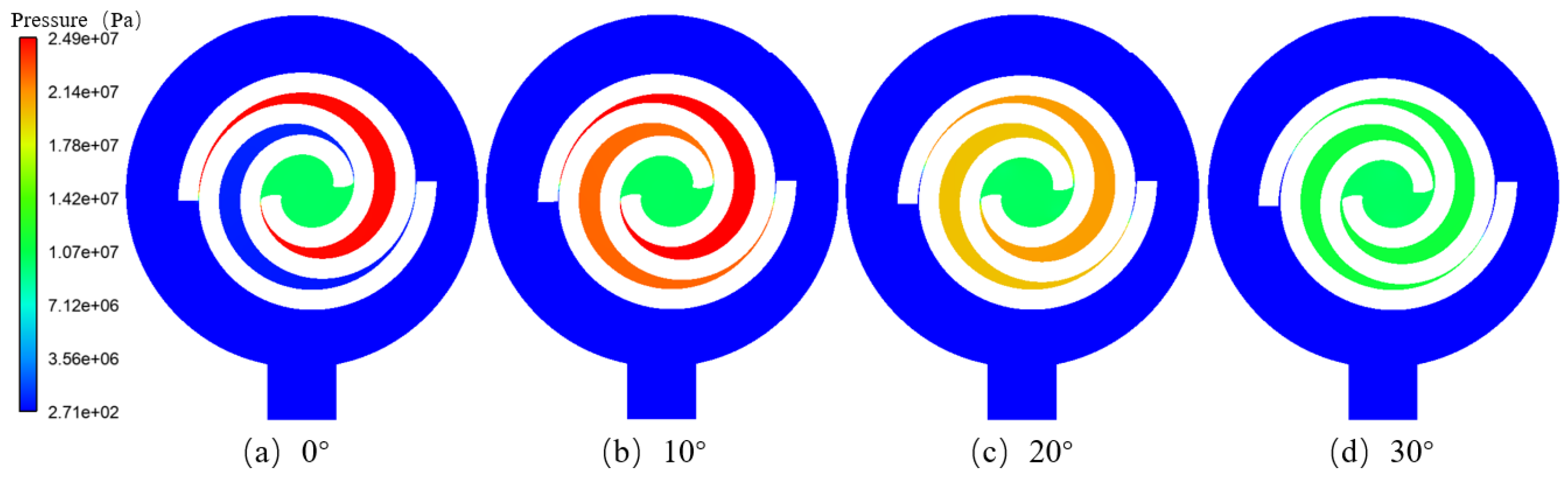
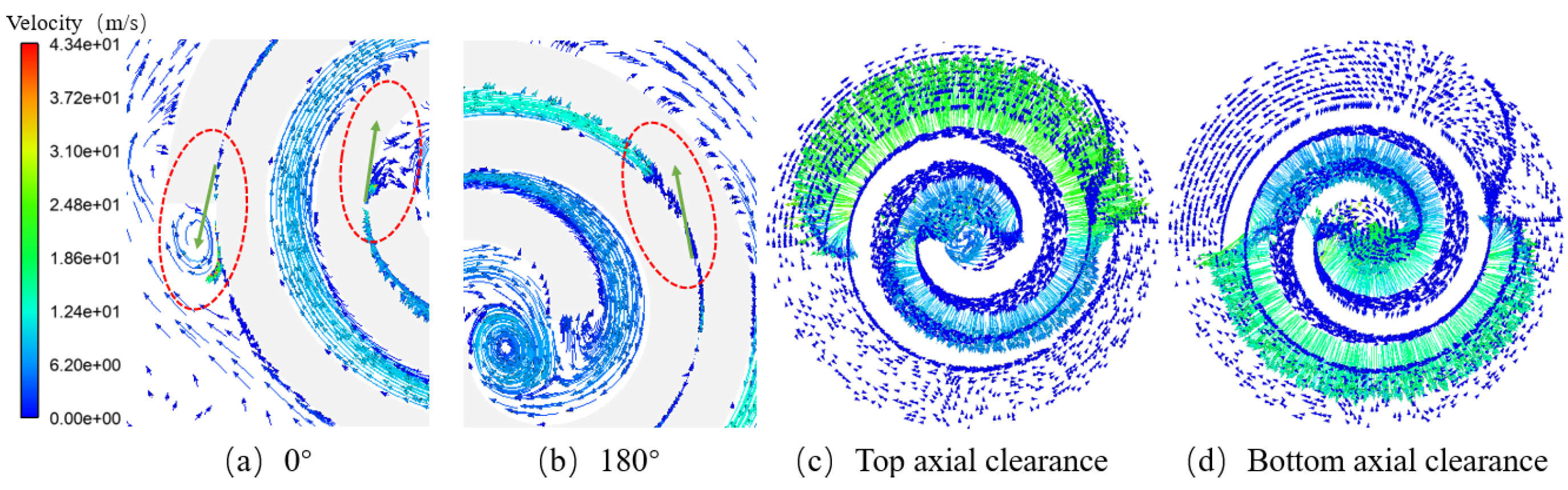
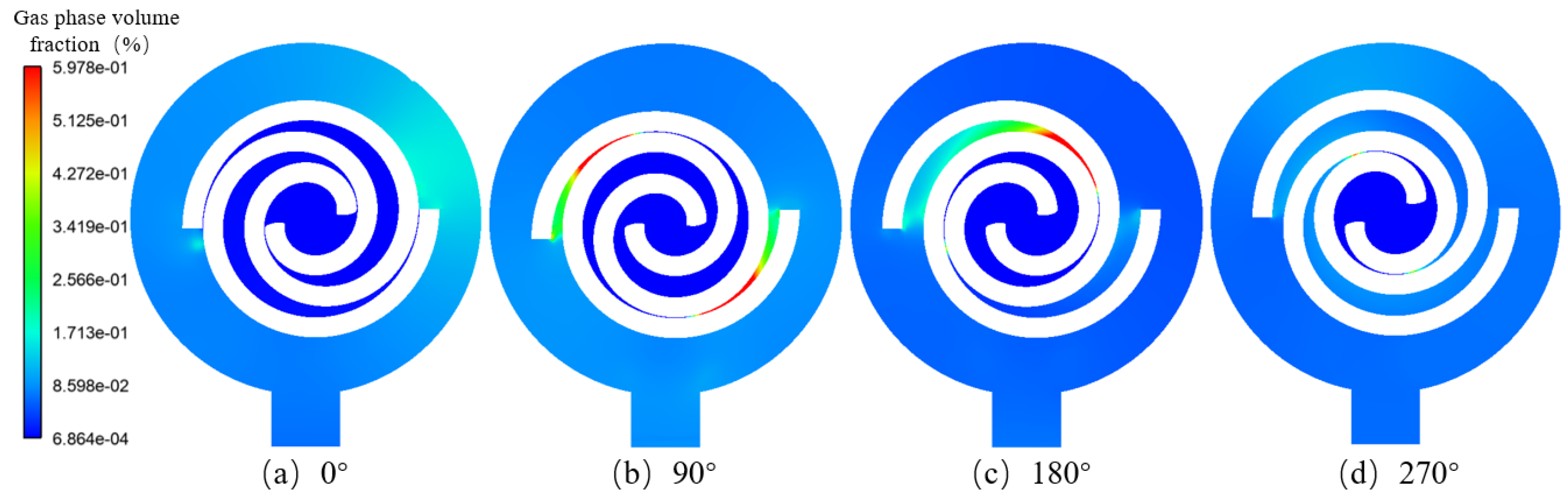
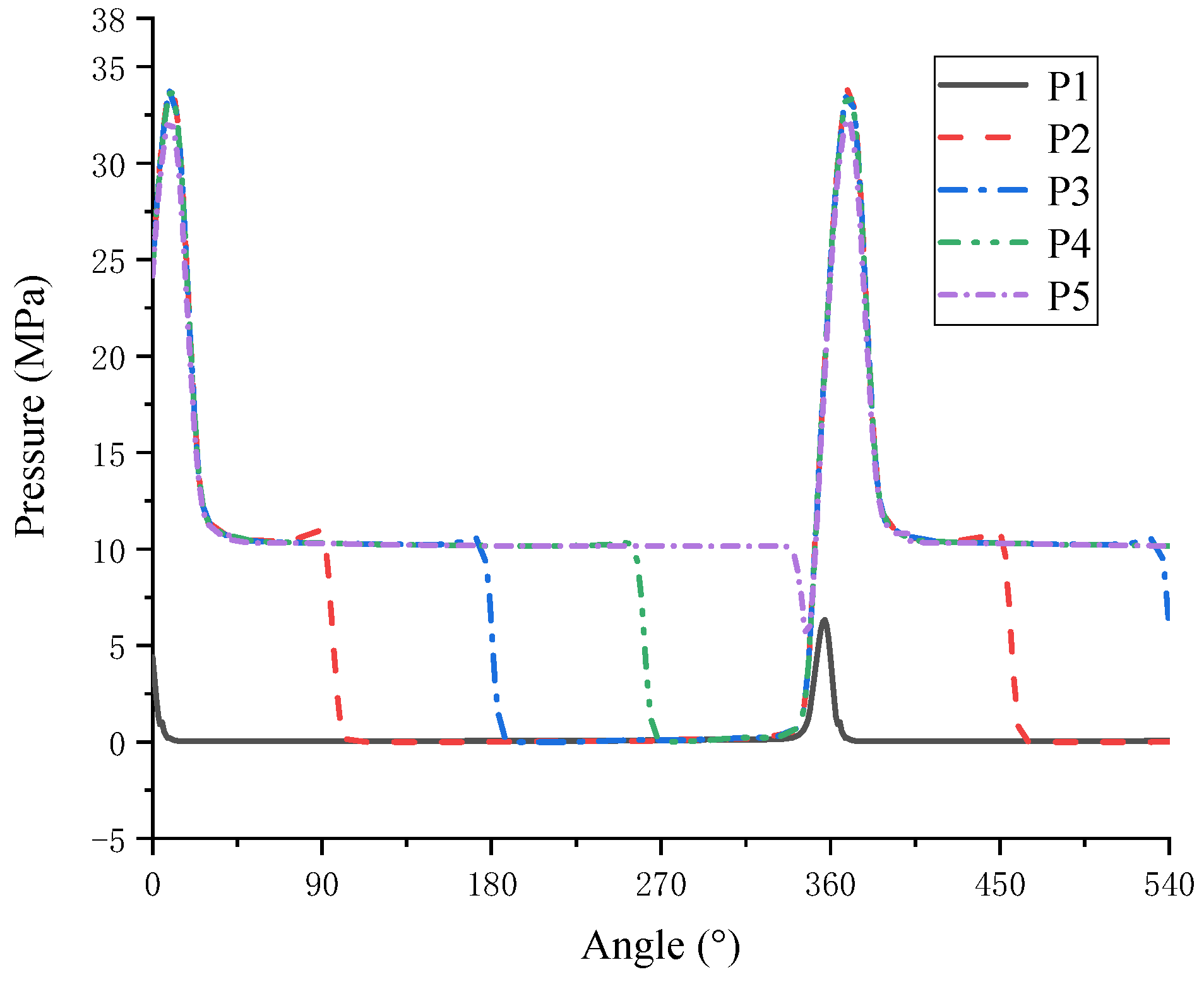
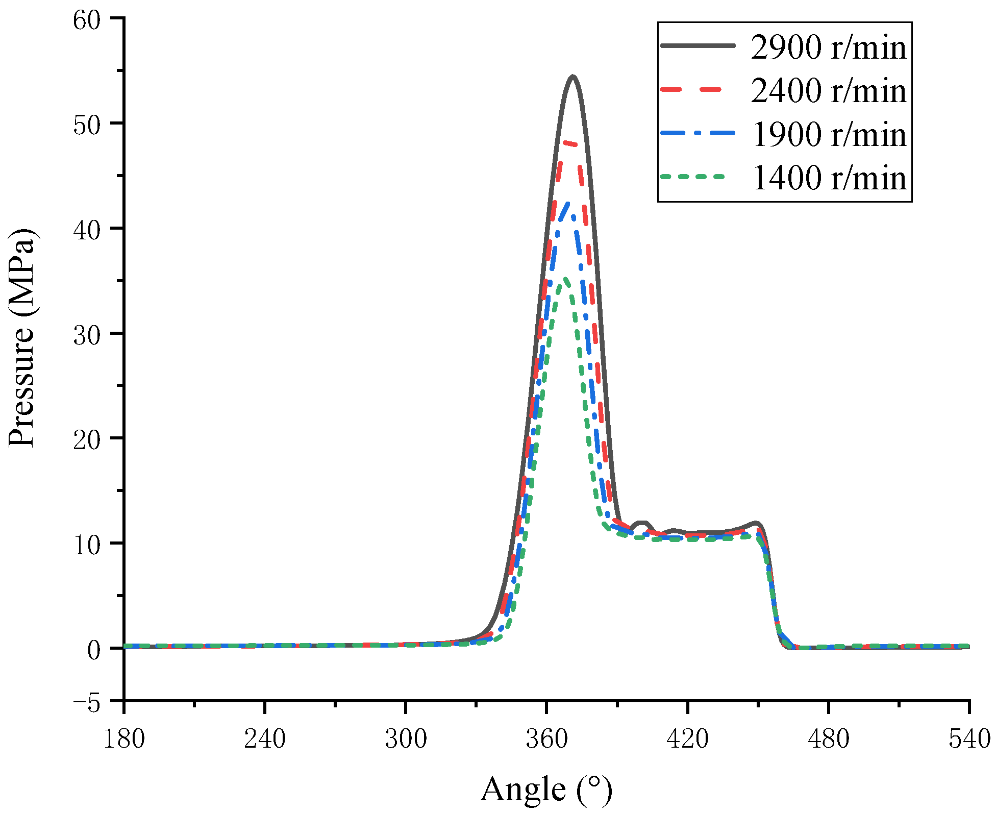
  • There is a phenomenon of the high-speed jet in the gap between the orbiting scroll and fixed scroll. The cavitation mainly occurs in the downstream area of the clearance. Due to the inherent volume variation characteristics of scroll pumps, the high-pressure pulsation occurs in the working chamber at the end of suction and the beginning of discharge.
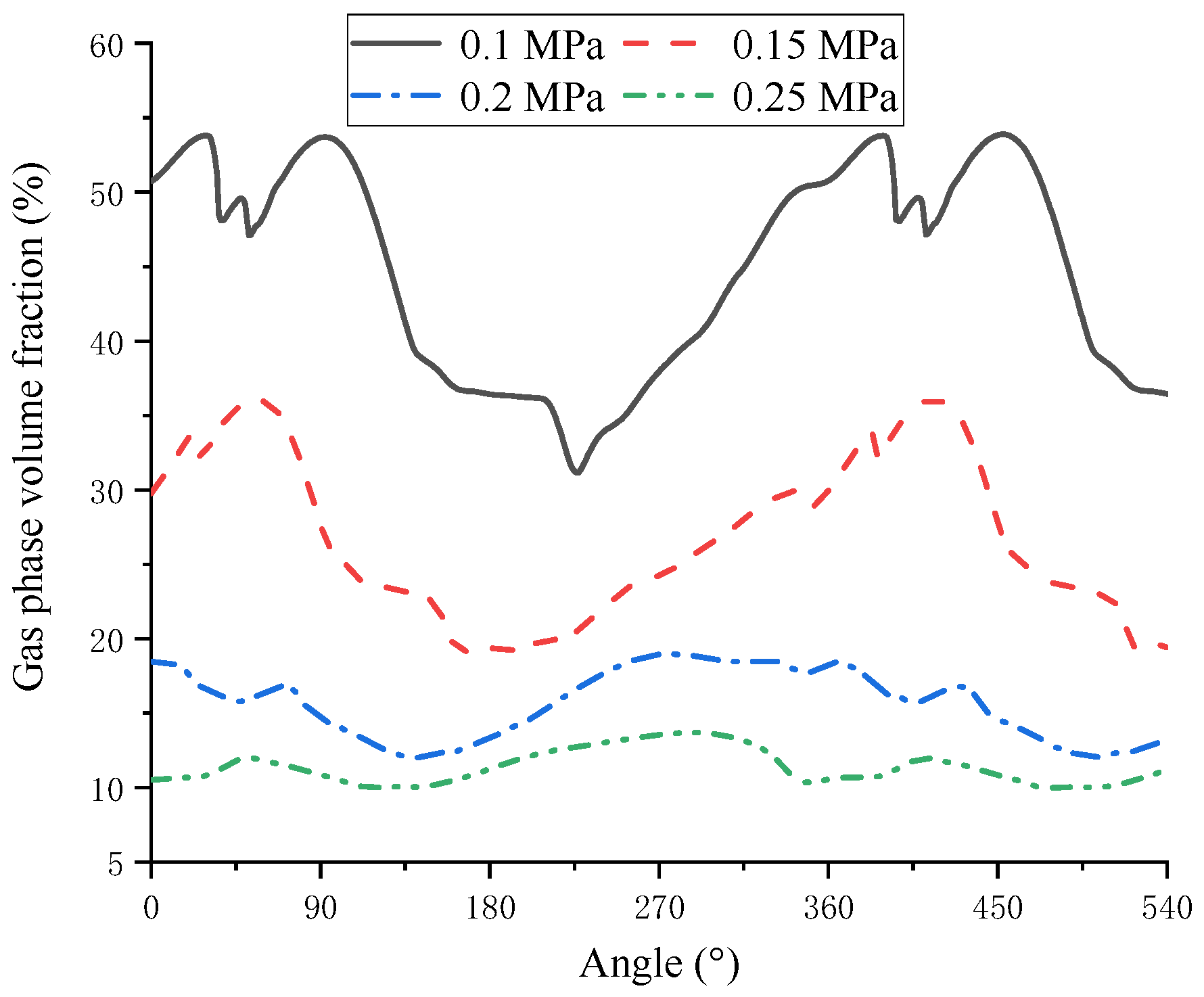
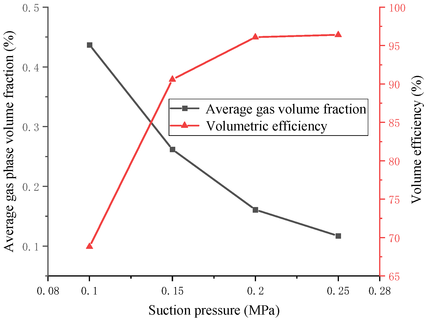
  • With the increase in rotating speed, cavitation intensifies, and the volumetric efficiency drops sharply at low oil suction pressure. Cavitation can be effectively reduced by increasing the suction pressure to ensure the pump performance at a high rotating speed.
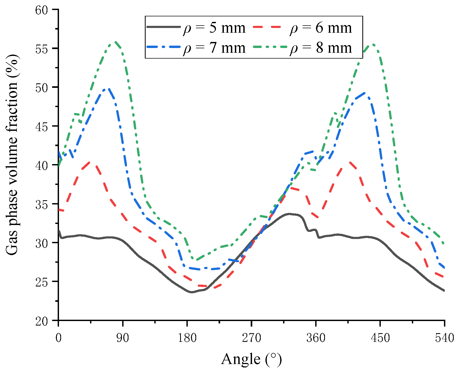
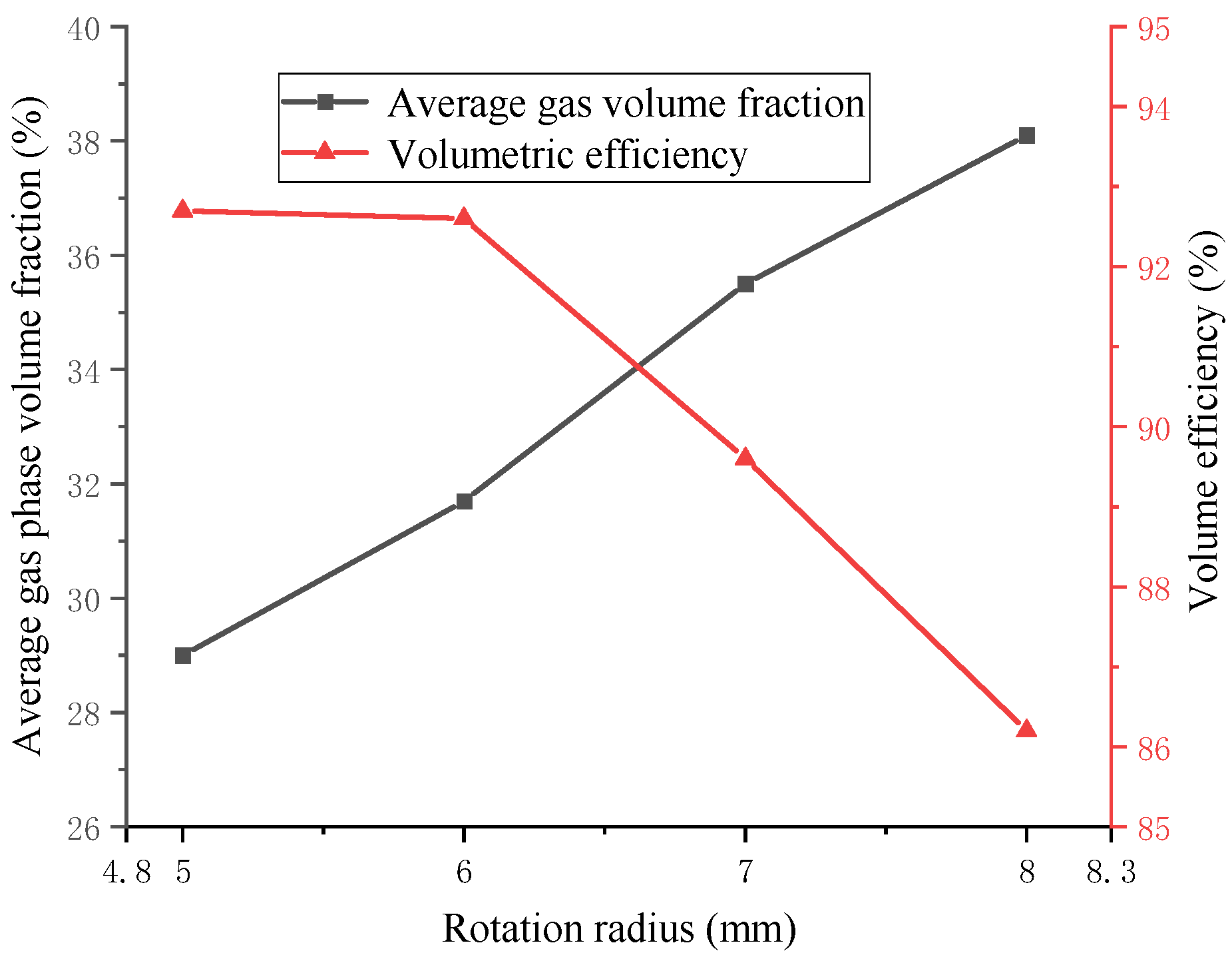
  • The larger the rotation radius is, the more obvious the cavitation is, and the greater the leakage is at the same discharge capacity. Therefore, the rotation radius of the scroll pump should not be too large. Based on this study, to ensure the operational performance of the scroll pump, the best rotation radius is 5 to 6 mm.
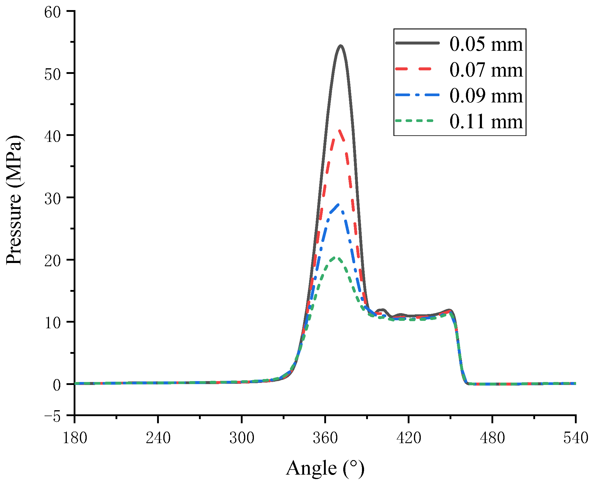
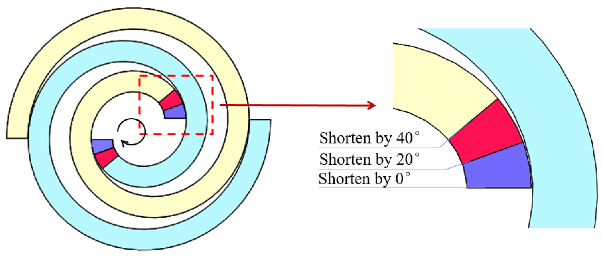
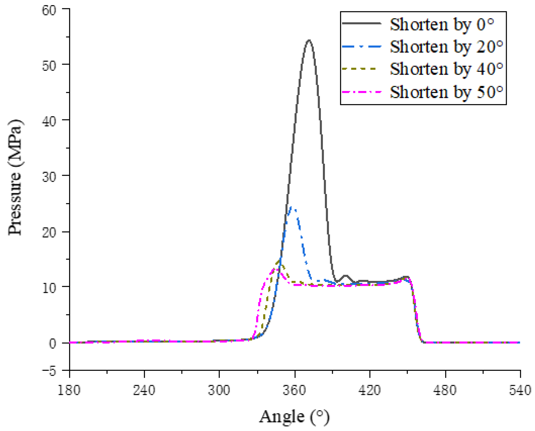
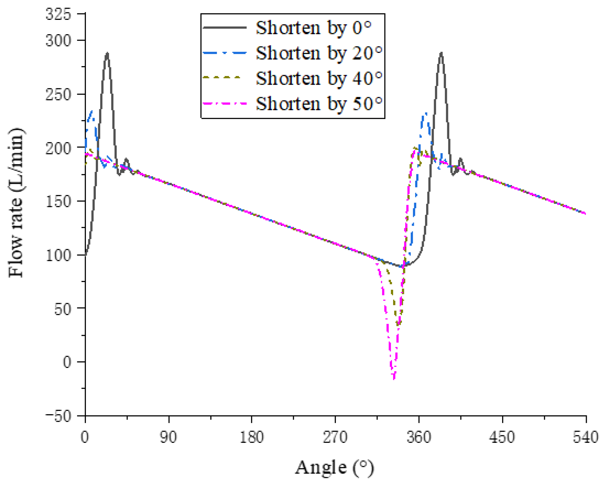
  • The pressure pulsation can be effectively improved by reducing the rotating speed and increasing the axial clearance, but the volumetric efficiency would be reduced. The pressure pulsation can be weakened by shortening the scroll profile, which was verified by simulation. When the profile is shortened by 30°, the pressure peak drops to 17.2 MPa, and the volumetric efficiency can be maintained at 97.3%.

Author Contributions

Writing—original draft: S.T., writing—review and editing: K.D.; supervision, validation: Y.Z.; formal analysis: Q.Y.; investigation, data curation: G.L.; conceptualization: L.L. All authors have read and agreed to the published version of the manuscript.

Funding

This work was supported by the Taishan Scholar Program of Shandong (No. tsqn201812073).

Institutional Review Board Statement

Not applicable.

Informed Consent Statement

Not applicable.

Data Availability Statement

Not applicable.

Conflicts of Interest

The authors declare that they have no conflict of interest.

References

  1. Tankasala, S.; Vacca, A. Theoretical Analysis and Design of a Variable Delivery External Gear Pump for Low and Medium Pressure Applications. J. Mech. Des. 2019, 141, 013401. [Google Scholar] [CrossRef]
  2. Battarra, M.; Mucchi, E. On the relation between vane geometry and theoretical flow ripple in balanced vane pumps. Mech. Mach. Theory 2020, 146, 103736. [Google Scholar] [CrossRef]
  3. Chao, Q.; Tao, J.; Lei, J.; Wei, X.; Liu, C.; Wang, Y.; Meng, L. Fast scaling approach based on cavitation conditions to estimate the speed limitation for axial piston pump design. Front. Mech. Eng. 2021, 16, 176–185. [Google Scholar] [CrossRef]
  4. Antoniak, P.; Stryczek, J. Visualization study of the flow processes and phenomena in the external gear pump. Arch. Civ. Mech. Eng. 2018, 18, 1103–1115. [Google Scholar] [CrossRef]
  5. Stryczek, J.; Antoniak, P.; Jakhno, O.; Kostyuk, D.; Kryuchkov, A.; Belov, G.; Rodionov, L. Visualisation research of the flow processes in the outlet chamber–outlet bridge–inlet chamber zone of the gear pumps. Arch. Civ. Mech. Eng. 2015, 15, 95–108. [Google Scholar] [CrossRef]
  6. Buono, D.; Cola FDSd Senatore, A.; Frosina, E.; Buccilli, G.; Harrison, J. Modelling Approach on a Gerotor Pump Working in Cavitation Conditions. Energy Procedia 2016, 101, 701–709. [Google Scholar] [CrossRef]
  7. Chai, H.; Yang, G.; Wu, G.; Bai, G.; Li, W. Research on Flow Characteristics of Straight Line Conjugate Internal Meshing Gear Pump. Processes 2020, 8, 269. [Google Scholar] [CrossRef] [Green Version]
  8. Cheng, Y.; Wang, X.; Chai, H.; Sun, T.; Shahzad, H.; Rehman, W.U. The Theoretical Performance Analysis and Numerical Simulation of the Cylindrical Vane Pump. Arab. J. Sci. Eng. 2021, 46, 2947–2961. [Google Scholar] [CrossRef]
  9. Li, Y.; Guo, D.; Li, X. Mitigation of radial exciting force of rotary lobe pump by gradually varied gap. Eng. Appl. Comput. Fluid Mech. 2018, 12, 711–723. [Google Scholar] [CrossRef]
  10. Li, Y.; Du, J.; Guo, D. Numerical research on viscous oil flow characteristics inside the rotor cavity of rotary lobe pump. J. Braz. Soc. Mech. Sci. Eng. 2019, 41, 274. [Google Scholar] [CrossRef]
  11. Rundo, M.; Altare, G.; Casoli, P. Simulation of the Filling Capability in Vane Pumps. Energies 2019, 12, 283. [Google Scholar] [CrossRef] [Green Version]
  12. Zheng, S.; Wei, M.; Hu, C.; Song, P.; Tian, R. Flow characteristics of tangential leakage in a scroll compressor for automobile heat pump with CO2. Sci. China Technol. Sci. 2021, 64, 971–983. [Google Scholar] [CrossRef]
  13. Zhao, R.; Li, W.; Zhuge, W. Unsteady characteristic and flow mechanism of a scroll compressor with novel discharge port for electric vehicle air conditioning. Int. J. Refrig. 2020, 118, 403–414. [Google Scholar] [CrossRef]
  14. Sun, S.; Wu, K.; Guo, P.; Yan, J. Analysis of the three-dimensional transient flow in a scroll refrigeration compressor. Appl. Therm. Eng. 2017, 127, 1086–1094. [Google Scholar] [CrossRef]
  15. Sun, S.; Wu, K.; Guo, P.; Luo, X. Numerical analysis of the transient flow in a scroll refrigeration compressor. IOP Conf. Ser. Mater. Sci. Eng. 2017, 232, 012050. [Google Scholar] [CrossRef] [Green Version]
  16. Sun, S.; Wang, X.; Guo, P.; Song, Z. Investigation on the modifications of the suction flow passage in a scroll refrigeration compressor. Appl. Therm. Eng. 2020, 170, 115031. [Google Scholar] [CrossRef]
  17. Zhang, Q.; Feng, J.; Wen, J.; Peng, X. 3D transient CFD modelling of a scroll-type hydrogen pump used in FCVs. Int. J. Hydrog. Energy 2018, 43, 19231–19241. [Google Scholar] [CrossRef]
  18. Feng, J.; Zhang, Q.; Hou, T.; Peng, X. Dynamics characteristics analysis of the oil-free scroll hydrogen recirculating pump based on multibody dynamics simulation. Int. J. Hydrog. Energy 2021, 46, 5699–5713. [Google Scholar]
  19. Wei, M.; Song, P.; Zhao, B.; Shi, L.; Wang, Z.; Ma, C. Unsteady flow in the suction process of a scroll expander for an ORC waste heat recovery system. Appl. Therm. Eng. 2015, 78, 460–470. [Google Scholar] [CrossRef]
  20. Song, P.; Zhuge, W.; Zhang, Y.; Zhang, L.; Duan, H. Unsteady Leakage Flow Through Axial Clearance of an ORC Scroll Expander. Energy Procedia 2017, 129, 355–362. [Google Scholar] [CrossRef]
  21. Emhardt, S.; Tian, G.; Song, P.; Chew, J.; Wei, M. CFD modelling of small scale ORC scroll expanders using variable wall thicknesses. Energy 2020, 199, 117399. [Google Scholar] [CrossRef] [Green Version]
  22. Yue, X.; Lu, Y.; Zhang, Y.; Ba, D.; Wang, G.; Zhang, Z. Computational fluid dynamics simulation study of gas flow in dry scroll vacuum pump. Vacuum 2015, 116, 144–152. [Google Scholar] [CrossRef]
  23. Yue, X.; Zhang, Y.; Su, Z.; Ba, D.; Wang, G.; Zhang, Z. CFD-based analysis of gas flow in dry scroll vacuum pump. Vacuum 2017, 139, 127–135. [Google Scholar] [CrossRef]
  24. Wang, J.; Dong, L.; Xi, Z.; Cao, C.; Wang, Z. Construction and simulation of novel asymmetrical scroll wraps for scroll vacuum pumps. Vacuum 2021, 183, 109837. [Google Scholar] [CrossRef]
  25. Kritmaitree, P.; Akiyama, M.; Hino, R.; Kaminaga, M.; Terada, A. Prediction of Flow Patterns and Pressure Distributions in Suction Process of Volumetric Scroll Pump. J. Nucl. Sci. Technol. 2000, 37, 996–998. [Google Scholar] [CrossRef]
  26. Kritmaitree, P.; Akiyama, M.; Hino, R.; Kaminaga, M.; Terada, A. Analytical Study of Volumetric Scroll Pump for Liquid Hydrogen Circulating System. J. Nucl. Sci. Technol. 2002, 39, 101–107. [Google Scholar] [CrossRef]
  27. Sun, S.; Guo, P.; Huang, Y.; Zuo, J.L.; Luo, X. Numerical analysis on the cavitation and unsteady flow in a scroll hydraulic pump. IOP Conf. Ser. Mater. Sci. Eng. 2016, 129, 012028. [Google Scholar] [CrossRef] [Green Version]
  28. Gu, Z.; Yu, Y.; Feng, S. Scroll Compressors and Other Scroll Machinery; Shaanxi Science and Technology Press: Xi’an, China, 1998. (In Chinese) [Google Scholar]
  29. Singhal, A.K.; Athavale, M.M.; Li, H.; Jiang, Y. Mathematical Basis and Validation of the Full Cavitation Model. J. Fluids Eng. 2002, 124, 617–624. [Google Scholar] [CrossRef]
Figure 1. Working principle of scroll pump.
Processes 09 01705 g001
Figure 2. Two-dimensional schematic diagram of the scroll pump.
Processes 09 01705 g002
Figure 3. Variation of working chamber volume with rotation angle.
Processes 09 01705 g003
Figure 4. Fluid domain and grids of scroll pump.
Processes 09 01705 g004
Figure 5. Pressure contour at different rotation angles.
Processes 09 01705 g005
Figure 6. Velocity vector diagram.
Processes 09 01705 g006
Figure 7. Gas-phase volume fraction at different rotation angles.
Processes 09 01705 g007
Figure 8. Pressure curve of monitoring points.
Processes 09 01705 g008
Figure 9. Gas volume fraction at different rotating speeds.
Processes 09 01705 g009
Figure 10. Outlet flow at different rotating speeds.
Processes 09 01705 g010
Figure 11. Average gas volume fraction and volumetric efficiency at different rotating speeds.
Processes 09 01705 g011
Figure 12. Gas-phase volume fraction at different rotation radii.
Processes 09 01705 g012
Figure 13. Average gas-phase volume fraction and volume efficiency at different rotation radii.
Processes 09 01705 g013
Figure 14. Gas-phase volume fraction at different oil suction pressure.
Processes 09 01705 g014
Figure 15. Average gas volume fraction and volumetric efficiency at different suction pressures.
Processes 09 01705 g015
Figure 16. The pressure of P2 at different rotating speeds.
Processes 09 01705 g016
Figure 17. The pressure of P2 at different axial clearances.
Processes 09 01705 g017
Figure 18. Schematic diagram of scroll profile shortening position.
Processes 09 01705 g018
Figure 19. The pressure of P2 at different profile lengths.
Processes 09 01705 g019
Figure 20. Outlet flow at different line lengths.
Processes 09 01705 g020
Table 1. Parameters of scroll pump.
ParameterValueParameterValue
Base radius a (mm)4.447Tooth depth H (mm)21.220
Pitch Pt (mm)30.0Rotation radius ρ (mm)5.000
Wall thickness t (mm)10.0Axial clearance (mm)0.050
Number of turns1.5Meshing clearance (mm)0.050
Involute termination angle   Φ E (rad)Discharge capacity V (mL/r)50.0
Table 2. Grid independence verification.
Simulation CaseNumber of GridsVolumetric Efficiency (%)
114365195.703
227252696.287
349315496.399
464954696.392
Table 3. Volumetric efficiency at different conditions.
ConditionParameterPressure Peak (MPa)Volumetric Efficiency (%)
Rotating speed (r/min)290054.496.4
240048.795.5
190042.394.3
140035.192.3
Axial clearance (mm)0.0554.496.4
0.0740.791.6
0.0928.884.8
0.1120.376.1
Table 4. Volumetric efficiency under different profile lengths.
Profile LengthPressure Pulsation Peak (MPa)Volumetric
Efficiency (%)
Input Power
(kW)
Shorten by 0°54.496.431.21
Shorten by 10°38.197.028.79
Shorten by 20°24.697.326.93
Shorten by 30°17.297.326.24
Shorten by 40°14.696.826.05
Shorten by 50°13.395.225.91
Publisher’s Note: MDPI stays neutral with regard to jurisdictional claims in published maps and institutional affiliations.

