Article

Condensate-Banking Removal and Gas-Production Enhancement Using Thermochemical Injection: A Field-Scale Simulation

1
College of Petroleum Engineering and Geosciences, King Fahd University of Petroleum and Minerals, Dhahran 31261, Saudi Arabia
2
Advanced Research Center (EXPEC ARC), Dhahran 31311, Saudi Arabia
*
Author to whom correspondence should be addressed.
Processes 2020, 8(6), 727; https://doi.org/10.3390/pr8060727
Submission received: 10 May 2020 / Revised: 18 June 2020 / Accepted: 20 June 2020 / Published: 23 June 2020
(This article belongs to the Section Energy Systems)

Abstract

:
Condensate-liquid accumulation in the vicinity of a well is known to curtail gas production up to 80%. Numerous approaches are employed to mitigate condensate banking and improve gas productivity. In this work, a field-scale simulation is presented for condensate damage removal in tight reservoirs using a thermochemical treatment strategy where heat and pressure are generated in situ. The impact of thermochemical injection on the gas recovery is also elucidated. A compositional simulator was utilized to assess the effectiveness of the suggested treatment on reducing the condensate damage and, thereby, improve the gas recovery. Compared to the base case, represented by an industry-standard gas injection strategy, simulation studies suggest a significantly improved hydrocarbon recovery performance upon thermochemical treatment of the near-wellbore zone. For the scenarios investigated, the application of thermochemicals allowed for an extension of the production plateau from 104 days, as determined for the reference gas injection case, to 683 days. This represents a 6.5-fold increase in production plateau time, boosting gas recovery from 25 to 89%. The improved recovery is attributed to the reduction of both capillary pressure and condensate viscosity. The presented work is crucial for designing and implementing thermochemical treatments in tight-gas reservoirs.

1. Introduction

Condensate banking constitutes a common challenge for hydrocarbon production from tight-gas reservoirs [1,2,3]. The reduction of reservoir pressure below dew point gives rise to condensate dropout [4,5,6]. Liquid accumulates near the wellbore, potentially reducing gas production by up to 80% [2,7,8]. Several methods are employed to remove condensate damage and restore gas productivity [3,9]. Gas injection and hydraulic fracturing are among the most effective treatments in mitigating condensate banking [10,11,12].
Generally, gas injection aims to either increase or maintain pressure in proximity of the wellbore above dew-point pressure [10,13,14], allowing for the revaporization of the condensate liquid into the gas phase [4,15,16]. Usually, gas injection is initiated every six to nine months depending on specific reservoir conditions [3,9]. Treatment involves the injection of hydrocarbon gases like methane, or nonhydrocarbon gases like nitrogen or carbon dioxide, in combination with a cyclic intervention approach [10,12,16,17,18]. The administration of carbon dioxide in a huff-and-puff configuration in particular shows great potential in mitigating condensate banking owing to the ability of CO2 gas to reduce the dew-point pressure of condensates, hence counteracting liquid dropout [12,19,20]. Notably, though, this procedure needs to be repeated about every 6 to 9 months to maintain its effectiveness, giving rise to logistical challenges associated with CO2 procurement, transportation, and on-site handling challenging its economic viability [3,9,21].
Alternatively, hydraulic fracturing may be used to mitigate condensate banking by creating longer conductive paths between wellbore and formation [9,11,22]. Fractures induce help to reduce pressure drop, and delay condensate dropout [11,23]. However, once reservoir pressure drops below dew point as a result of the ongoing depletion process, liquids precipitate and accumulate within fractures, and then impede gas flow towards the production well [3,9]. Solvent or gas injection may be used to vaporize the liquids and re-establish fracture conductivity [11,23].
Evidently, gas injection, hydraulic fracturing, or a combination thereof constitute pragmatic approaches to mitigating condensate banking. However, gas injection needs to be executed on a frequent basis to maintain its efficacy. Hydraulic fracturing only delays the inevitable development of a condensate bank. Hence, at some point, gas injection may be required to become part of the reservoir-management process. Needless to say, both gas-injection and hydraulic-fracturing treatments are of great concern with respect to project economics [3,9]. Therefore, in this paper, an innovative condensate-treatment concept based on thermochemical fluids (TCFs) is introduced [3,24,25,26,27]. Exploiting enthalpy associated with the thermochemical reaction allows for remarkable increases in pressure and temperature to be realized downhole [28,29]. The suggested treatment exhibits an attractive performance profile that can combat condensate-banking-related challenges for various types of gas reservoirs associated with carbonate, sandstone, and shale formations [27,30].
Figure 1 illustrates the concept of thermochemical injection for removing the condensate bank. Initially, during gas production, condensate liquid drops out and accumulates in the vicinity of the wellbore, thereby restricting gas flow towards the producing well. The injection of TCFs into the condensate-banking zone helps to reduce fluid viscosity and improve condensate mobility. Furthermore, in situ generated pressure and temperature increase associated with the thermochemical reaction provide additional driving force, enhancing the flow of the condensate liquid into the well. Several fluids, such as magnesium sulfate, sodium nitrate, and ammonium chloride solutions, may be used. Importantly, compared to conventional methods, the outlined process yielded higher thermal efficiency and lower energy loss compared to those of conventional gas-injection methods on an equimolar basis.
Given successful lab trials [24,25,26,27,30], this paper for the first time presents a field-scale simulation based on experimentally obtained data for condensate removal from gas reservoirs by means of a thermochemical treatment strategy. In addition, sensitivity analysis was conducted to study the impact of different wellbore conditions on gas-production rate. Furthermore, the relationship between condensate-bank development, and gas-production rate and flowing bottom-hole pressure was investigated. Lastly, the effectiveness of thermochemical treatments reflected in associated production profiles was contrasted with a conventional gas-injection approach.

2. Methodology

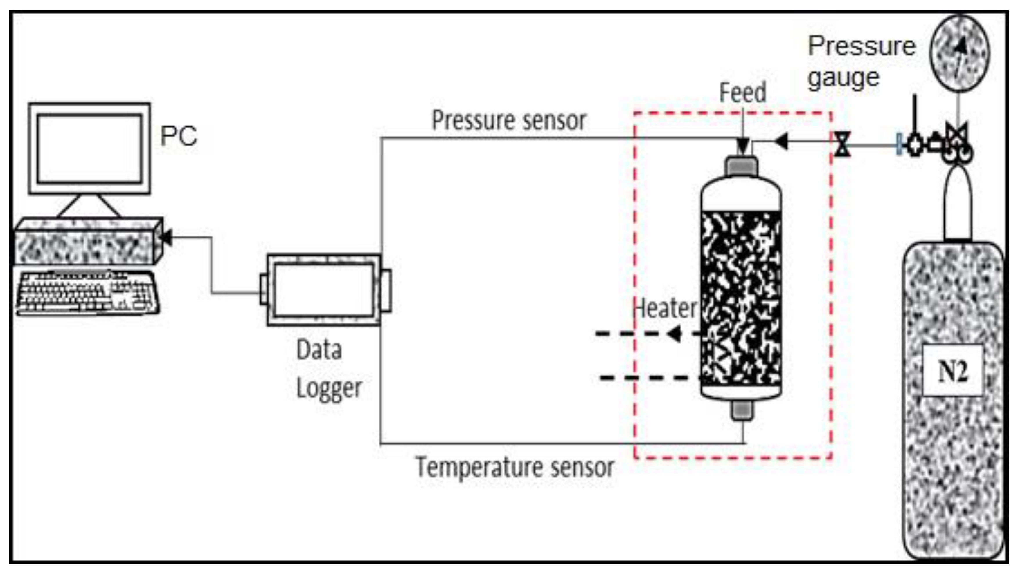
2.1. Process Description

The described thermochemical process constitutes the injection of two chemicals that mutually react under downhole conditions to generate heat and nitrogen, thereby significantly increasing pressure and temperature. The induced temperatures and pressures can yield changes in the excess of 533 K (500 °F) and 35 MPa (5000 psi), respectively, depending on injected TCF volume and chemical concentrations. In this work, two aqueous solutions (sodium nitrite NaNO2 and ammonium chloride NH4Cl) were used as thermochemical fluids. The thermochemical reaction is given by the following equation [24,29]:
NH 4 Cl + Na NO 2   NaCl + 2 H 2 O + N 2 + Δ H   ( heat )
The reaction could be accelerated by increasing temperature and/or lowering system pH below 4. During the reaction, the produced nitrogen gas ( N 2 ) led to a rise in pressure, and generated heat ( Δ H ) resulted in an increase in temperature. Consequently, TCF injection into a condensate region supported the revaporization of a portion of the condensate liquid, and the reduction of both condensate viscosity and density. Furthermore, in field applications, the chemical reaction could be triggered inside the reservoir formations to minimize risks associated with chemical reaction. Thermochemical fluids can be injected into the formation around the wellbore; then, acidic fluid is injected to lower pH, it can activate exothermic reactions within the reservoir formation.
During the experiment investigation, heat and pressure were monitored, and condensate properties were measured before and after introducing TCFs. Figure 2 displays the experiment configuration used to monitor the process. The setup consisted of a high-pressure and high-temperature (HPHT) reactor, pressure and temperature sensors, a heater, an N2 cylinder, and a data-acquisition system. Thermochemical fluids were injected into the HPHT reactor, and no rock sample was used in order to minimize the uncertainty associated with rock composition. Subsequently, the reaction was triggered by acetic acid. A pressure source (N2 cylinder) was utilized to study the reaction behavior for various pressures. High-accuracy sensors in combination with a data logging system were used to record the temperature and pressure profiles as a function of time.
Figure 3 summarizes the recorded temperature profiles resulting from the reaction at different initial system temperatures of 292, 314, 328, and 347 K (65, 105, 130, and 165 °F). For all temperatures, the reaction increased the in situ temperature by around 333.15 K (140 °F). Expectedly, for higher initial temperatures, temperature peaks were reached more quickly compared to lower initial-temperature conditions. The conversion of reactants as a function of time for various initial temperatures is plotted in Figure 4. The time to reach the peak temperature decreased from 1000 s, for an initial temperature of 292 K (65 °F), to around 320 s, for an operating temperature of about 347 K (165 °F).
In addition, enthalpy impact on condensate liquids was investigated. Figure 5 and Figure 6 illustrate the temperature and pressure profiles for two selected cases, only TCFs and a thermochemical-condensate system. Higher temperatures were recorded for the pure TCF system, while introducing the condensate liquid into the TCF system led to a reduction of the temperature, measured by around 7.4 K (11 °F) due to the added thermal capacity of the condensate. The condensate properties were changed considerably after the chemical reaction occurred. Rheological measurements substantiated condensate-viscosity reduction from 0.94 to 0.57 cP after TCF injection, amounting to a 39% decrease. Upon injection, generated pressure increased the gradient to push the condensate liquid towards the producing well. Importantly, the pressure generated multiple fractures (Figure 7) in the treated formations, thereby increasing pore-throat size and reducing capillary pressure by up to 51% [25]. The reduction in capillary pressure due to the creation of multiple fractures can be explained by the following equation [25,31]:
P c = 2 σ c o s θ r ,
where P c is capillary pressure, σ is interfacial tension, θ is contact angle, and r is pore-throat size.

2.2. Reservoir Model

An advanced equation-of-state (EoS) compositional and unconventional simulator (GEM) from Computer Modelling Group (CMG) software was utilized. The used data were collected from the available literature [32,33,34]. Ayub and Ramadan [12] examined reservoirs with respect to the areal extensions and associated drainage areas in the vicinity of the gas-production well. They reported that a 1 by 1 km sector could accurately represent the actual behavior of pressure depletion for a gas-condensate reservoir. Consequently, the reservoir was built around a Cartesian grid covering a square area of 1 km2. Figure 8 provides an overview of the reservoir model used in this work. The initial reservoir conditions are listed in Table 1. Vertical heterogeneity is captured by defining four layers with permeabilities ranging from 5 to 315 mD. On the basis of field data reported by Whitson and Kuntadi [34], reservoir porosity was given with 0.13, initial reservoir pressure with 48.3 MPa (7000 psi), temperature with 408 K (275 °F), and rock compressibility with 3.5e–8 1/Mpa (5.0e–6 1/psia). A single well was completed in the model center, and production simulated for a total of five years. Two wellbore constraints were applied with minimal flowing bottom-hole pressure of 10.4 MPa (1500 psi) and maximal flow rate of 30 MMSCFD.
In addition, relative-permeability curves were generated using available correlations in CMG software based on Corey’s model [35]. Figure 9 and Figure 10 summarize the relative-permeability curves used in this work, respectively.

2.3. Fluid Model

The fluid-property-characterization tool (WinProp) was employed to develop the EoS model on the basis of the Peng–Robinson framework using the fluid composition listed in Table 2. Figure 11 details the resulting two-phase envelope. During production, reservoir pressure decreased entering the two-phase region, allowing for gas and liquid condensate to coexist. Generally, it can be assumed that the gas is produced under isothermal conditions. Heat loss from the reservoir was considered negligible due to the poor thermal conductivity of the reservoir rock and the insulating nature of the overburden formations. Importantly, constant composition expansion (CCE) measurements were used to validate the developed fluid model. An acceptable match was achieved between experiment measurements and simulation results, as evidenced in Figure 12.

3. Results and Discussion

The simulation work was conducted in two stages: condensate development and thermochemical injection. First, the impact of wellbore conditions on condensate formation was studied. The effects of flowing bottom-hole pressure and gas-production rate on the development of condensate banking were examined. A sharp decrease in the gas-production profile served as an indicator for condensate banking. Next, production plateau time, defined as the duration of stabilized gas production, was calculated as functions of both gas-flow rate and flowing bottom-hole pressure. During the second stage, the thermochemical treatment was initiated. The effects of in situ generated heat, and pressure triggered by the thermochemical reaction on condensate bank and gas production were studied. Lastly, the effectiveness of the thermochemical treatment was compared with the efficiency of the conventional gas-injection approach in terms of stabilized production times and total gas recovery.

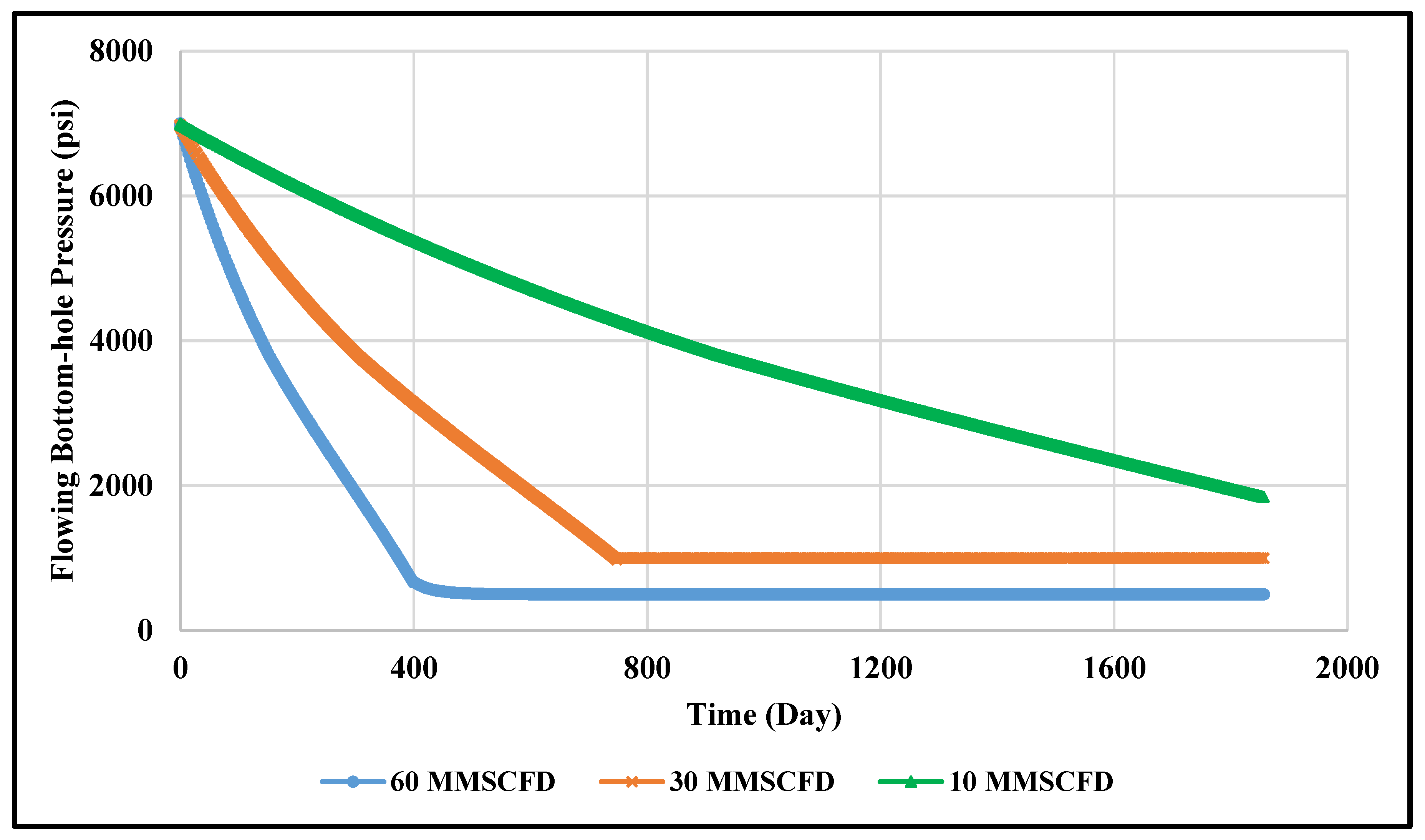
3.1. Impact of Flowing Bottom-Hole Pressure

The relationship between the evolution of the condensate bank and associated flowing bottom-hole pressure was studied by producing the hydrocarbon gas at different levels of flowing bottom-hole pressure (BHP). Figure 13 summarizes the profiles of gas-flow rates at flowing bottom-hole pressure of 3.5, 6.9, and 10.4 MPa (500, 1000, and 1500 psi), respectively. Production was constrained to a maximal gas-flow rate of 30 MMSCFD. Initially, the well produced at a constant production rate with bottom-hole pressure decreasing as a result of the depletion process. Once pressure reached a specified BHP value (500, 1000, and 1500 psi), it was kept constant, and production rate correspondingly decreased until it reached 0 MMSCFD, revealing that the well had been killed due to condensate banking. At this point, the relationship between stabilized gas-production rate and flowing bottom-hole pressure was determined. Figure 14 plots the production plateau as a function of flowing bottom-hole pressure. Evidently, a decrease in flowing bottom-hole pressure allowed for sustaining the production plateau for increased periods of time. For example, the production plateau could be increased by around 13% by reducing flowing bottom-hole pressure from 10.4 to 6.9 MPa (1500 to 1000 psi). However, curtailing flowing bottom-hole pressure could exacerbate condensate dropout near the wellbore.

3.2. Impact of Gas-Production Rate

Figure 15 encapsulates gas-production profiles for gas-flow rates of 10, 30, and 60 MMSCFD, respectively. The corresponding flowing bottom-hole pressure profiles are plotted in Figure 16. It can be observed that a constant production rate of 60 MMSCFD could only be sustained for 400 days, with the rate sharply dropping thereafter due to flow impediments associated with condensate banking. Naturally, reducing gas-flow rate from 60 to 10 MMSCFD postpones the onset of liquid dropout. Plotting the duration of the production plateau maintained in days versus stabilized gas-flow rate suggested exponential relation, as indicated in Figure 17.

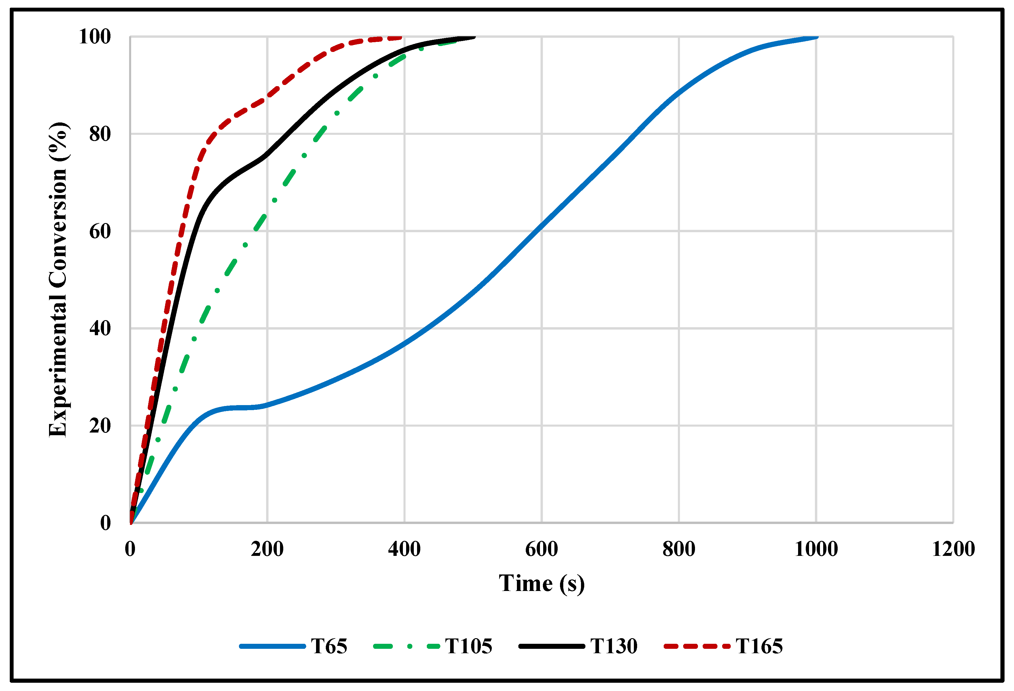
3.3. Thermochemical Treatment

The overall impact on gas production upon injection of thermochemical fluids into a gas-condensate reservoir can be divided into three major components, all of which were included in the model. First, the reaction products, mainly steam and nitrogen, yield an increase in pressure of up to 34.5 MPa (5000 psi) [24,28,29]. Thus, this effect finds equivalency in standard nitrogen injection. Second, the released heat, able to boost temperatures in the order of 422 K (300 °F), promotes a reduction in viscosity [28]. Third, the pressure pulse resulting from released enthalpy stimulates the formation by creating microfractures. This particular effect was integrated by adjusting capillary pressure on the basis of the work of Hassan et al. [9,25], who reported a reduction of the former by around 51%.
Figure 18 exemplifies the profiles of gas-flow rate and flowing bottom-hole pressure before and after thermochemical treatment. After 668 days of gas production, flowing bottom-hole pressure dramatically dropped, resulting in diminished gas-flow rate due to condensate development. At this point, gas production was halted, and chemical treatment commenced. In total, three treatment cycles were performed; a chemical concentration of 1 molar and total chemical volume of 1000 bbl were utilized. Each cycle was initiated with the injection of the chemicals, followed by a one-week soaking period. After completion of the cycles, production continued applying a maximal gas-flow rate of 30 MMSCFD, and minimal flowing bottom-hole pressure of 10.4 MPa (1500 psi). The intervention raised pressure and temperature in the near-wellbore region in excess of 31 MPa (4500 psi) and 324.8 K (125 °F), respectively. Consequently, as illustrated in Figure 19, liquids were revaporized, allowing for 683 additional days of gas-flow rate at 30 MMSCFD, succeeding the remedial efforts (Figure 18).

3.4. Comparison Analysis

The performance of the thermochemical treatment was compared to that of a conventional gas injection approach. The gas-injection process was simulated using reservoir and wellbore conditions similar to thermochemical injection. The production well was shut in after 668 days; subsequently, a mixture of N2, CO2, and CH4 gases was injected in three cycles for a total of one month. All other parameters were kept the same with respect to the thermochemical treatment. Figure 20 summarizes profiles for gas production and the corresponding flowing bottom-hole pressures pre- and post-treatment. After the gas-injection treatment, production was stable only for a period of 104 days (3.5 months). With reference to Figure 18, the thermochemical-based strategy enabled a sustained gas-production rate for a period of 683 days (22.7 months) for equal reservoir and well conditions, extending the production plateau by a factor of 6.5 compared to the gas-injection case.
Cumulative gas production is plotted in Figure 21. The conventional approach only allowed for a production of 23.2 MMMSCF, equivalent to total gas recovery of about 25% of hydrocarbons in place. In contrast, the application of thermochemicals improved gas recovery by a factor of 1.76 to 40.8 MMMSCF, corresponding to a total recovery of about 89% of the gas in place. Given that the injected gas had a similar composition to that of reservoir fluids, no chemical reaction was expected, and only condensate revaporization took place. Gas injection only increases pressure in the near-wellbore region, fostering the revaporization of the condensate liquid, thereby improving gas flow into wellbore [16,17]. Thermochemical injection, however, not only increases pressure, but also reduces capillary forces and decreases condensate viscosity [24,25,26,27].

4. Conclusions

This work presented a field-scale simulation quantifying the effectiveness of thermochemical injection for removing the condensate bank, thereby improving gas recovery. The following conclusions could be drawn from this work:
  • Compared to conventional gas-injection treatment, the thermochemical approach was found to be vastly superior in coping with condensate-banking-related production issues.
  • The simulation work indicated that thermochemical injection could restore the initial reservoir condition and sustain gas production for more than 680 days, compared to 104 days using gas-injection treatment.
  • For the particular model used in this investigation, total gas recovery for the thermochemical-based procedure was 89%, compared to 25% for the traditional gas-injection approach.
  • In the case of the thermochemical-based approach, the exothermic nature of the thermochemical reaction released pressure and heat, thereby increasing pressure around the wellbore, and heating fluids in this region.
  • Edicts reacted rather violently, giving rise to a pressure pulse, fostering the creation of microfractures accompanied by an according reduction in capillary pressure.

Author Contributions

Conceptualization, M.M., A.A.-M., and A.A.-N.; investigation, A.H. and M.A.; project administration, M.M. and A.A.-N.; supervision, M.M., A.A.-M., and A.A.-N.; validation, M.M., A.A.-M., and A.A.-N.; writing—original draft, A.H.; writing—review and editing, G.G. All authors have read and agreed to the published version of the manuscript.

Funding

This research was funded by Saudi Aramco under grant number CIPR2317.

Acknowledgments

The College of Petroleum and Geoscience at King Fahd University of Petroleum and Minerals, and Saudi Aramco are acknowledged for the support and permission to publish this work.

Conflicts of Interest

The authors declare no conflict of interest.

References

  1. Craft, B.C.; Hawkins, M. Applied Petroleum Reservoir Engineering, Chapter-2 Gas-Condensate Reservoirs; Prentice-Hall: Englewood Cliffs, NJ, USA, 1959; pp. 59–96. [Google Scholar]
  2. Al-Anazi, H.A.; Pope, G.A.; Sharma, M.M.; Metcalfe, R.S. Laboratory measurements of condensate blocking and treatment for both low and high permeability rocks. In Proceedings of the SPE Annual Technical Conference and Exhibition, SPE77546, San Antonio, TX, USA, 29 September–2 October 2002. [Google Scholar]
  3. Sayed, M.A.; Al-Muntasheri, G.A. Mitigation of the effects of condensate banking: A critical review. SPE Prod. Oper. 2016, 31, 85–102. [Google Scholar] [CrossRef]
  4. Muskat, M. Complete-Water-Drive Reservoirs, Chapter 11. Soc. Pet. Eng. 1949, 11, 528–644. [Google Scholar]
  5. Kniazeff, V.J.; Naville, S.A. Two-phase flow of volatile hydrocarbons. Soc. Petrol. Eng. J. 1965, 5, 37–44. [Google Scholar] [CrossRef]
  6. Novosad, Z. Composition and phase changes in testing and producing retrograde gas wells. SPE Res. Eng. 1996, 11, 231–235. [Google Scholar] [CrossRef]
  7. Ahmed, T. Reservoir Engineering Handbook, Chapter-1: Fundamentals of Reservoir Fluid Behavior; Gulf Publishing Company: Houston, TX, USA, 2000; pp. 1–28. [Google Scholar]
  8. Liu, D.; Sun, W.; Ren, D. Experimental Investigation of Pore Structure and Movable Fluid Traits in Tight Sandstone. Processes 2019, 7, 149. [Google Scholar] [CrossRef] [Green Version]
  9. Hassan, A.; Mahmoud, M.; Al-Majed, A.; Alawi, M.B.; Elkatatny, S.; BaTaweel, M.; Al-Nakhli, A. Gas condensate treatment: A critical review of materials, methods, field applications, and new solutions. J. Pet. Sci. Eng. 2019, 177, 602–613. [Google Scholar] [CrossRef]
  10. Linderman, J.T.; Al-Jenaibi, F.S.; Ghori, S.G. Feasibility study of substituting nitrogen for hydrocarbon in a gas recycle condensate reservoir. In Proceedings of the Abu Dhabi International Petroleum Exhibition and Conference, Abu Dhabi, UAE, 3–6 November 2008. [Google Scholar]
  11. Mahdiyar, H.; Jamiolahmady, M. Optimization of hydraulic fracture geometry in gas condensate reservoirs. Fuel 2014, 119, 27–37. [Google Scholar] [CrossRef]
  12. Ayub, M.; Ramadan, M. Mitigation of near wellbore gas-condensate by CO2 huff-n-puff injection: A simulation study. J. Pet. Sci. Eng. 2019, 175, 998–1027. [Google Scholar] [CrossRef]
  13. Luo, K.; Li, S.; Zheng, X.; Chen, G.; Dai, Z.; Liu, N. Experimental investigation into re-vaporization of retrograde condensate by lean gas injection. In Proceedings of the SPE Asia Pacific Oil and Gas Conference and Exhibition, Jakarta, Indonesia, 17–19 April 2001. [Google Scholar]
  14. Millan Arcia, E.; Gerder, Y.; Gil, J. A novel improved condensate–recovery method by cyclic supercritical CO2 injection. In Proceedings of the SPE Latin American and Caribbean Petroleum Engineering Conference, Buenos Aires, Argentina, 15–18 April 2007. [Google Scholar]
  15. Fevang, Ø.; Whitson, C.H. Modeling gas-condensate well deliverability. SPE Res. Eng. 1996, 11, 221–230. [Google Scholar] [CrossRef]
  16. Meng, X.; Sheng, J.J. Experimental and numerical study of huff-n-puff gas injection to re-vaporize liquid dropout in shale gas condensate reservoirs. J. Nat. Gas Sci. Eng. 2016, 35, 444–454. [Google Scholar] [CrossRef] [Green Version]
  17. Meng, X.; Sheng, J.J. Optimization of huff-n-puff gas injection in a shale gas condensate reservoir. J. Uncon. Oil Gas Res. 2016, 16, 34–44. [Google Scholar] [CrossRef] [Green Version]
  18. Wang, F.; Liu, Y.; Hu, C.; Wang, Y.; Shen, A.; Liang, S. Experimental study on feasibility of enhanced gas recovery through CO2 flooding in tight sandstone gas reservoirs. Processes 2018, 6, 214. [Google Scholar] [CrossRef] [Green Version]
  19. Odi, U. Analysis and potential of CO2 huff-n-puff for near Wellbore condensate removal and enhanced gas recovery. In Proceedings of the SPE Annual Technical Conference and Exhibition, Society of Petroleum Engineers, San Antonio, TX, USA, 8–10 October 2012. [Google Scholar]
  20. Monger, T.G.; Khakoo, A. The phase behavior of CO2–Appalachian oil systems. In Proceedings of the SPE Annual Technical Conference and Exhibition, San Antonio, TX, USA, 4–7 October 1981. [Google Scholar]
  21. Jia, B.; Tsau, J.S.; Barati, R. A review of the current progress of CO2 injection EOR and carbon storage in shale oil reservoirs. Fuel 2019, 236, 404–427. [Google Scholar] [CrossRef]
  22. Li, L.; Sheng, G.; Su, Y. Water-Gas Two-Phase Flow Behavior of Multi-Fractured Horizontal Wells in Shale Gas Reservoirs. Processes 2019, 7, 664. [Google Scholar] [CrossRef] [Green Version]
  23. Khan, M.N.; Siddiqui, F.I.; Mansur, S.; Ali, S.D. Hydraulic fracturing in gas condensate reservoirs: Successes, setbacks and lessons learnt. In Proceedings of the SPE/PAPG Annual Technical Conference, Society of Petroleum Engineers, Islamabad, Pakistan, 10–11 November 2010. [Google Scholar]
  24. Hassan, A.M.; Mahmoud, M.A.; Al-Majed, A.A.; Elkatatny, S.; Al-Nakhli, A.R.; Bataweel, M.A. Novel Technique to Eliminate Gas Condensation in Gas Condensate Reservoirs Using Thermochemical Fluids. Energy Fuels 2018, 32, 12843–12850. [Google Scholar] [CrossRef]
  25. Hassan, A.M.; Mahmoud, M.A.; Al-Majed, A.A.; Al-Nakhli, A.R.; Bataweel, M.A.; Elkatatny, S. Mitigation of Condensate Banking Using Thermochemical Treatment: Experimental and Analytical Study. Energies 2019, 12, 800. [Google Scholar] [CrossRef] [Green Version]
  26. Hassan, A.; Mahmoud, M.; Al-Majed, A.; Al-Shehri, D.; Al- Nakhli, A.; Bataweel, M. Gas Production from Gas Condensate Reservoirs Using Sustainable Environmentally Friendly Chemicals. Sustainability 2019, 11, 2838. [Google Scholar] [CrossRef] [Green Version]
  27. Al-Nakhli, A.; Hassan, A.; Mahmoud, M.; Al-Majed, A. Removal of Condensate Banking from Different Formations Using Thermochemical Treatment. In Proceedings of the Abu Dhabi International Petroleum Exhibition & Conference, Society of Petroleum Engineers, Abu Dhabi, UAE, 11–14 November 2019. [Google Scholar]
  28. Al-Nakhli, A.R.; Sukkar, L.A.; Arukhe, J.; Mulhem, A.; Mohannad, A.; Ayub, M.; Arifin, M. In-Situ steam generation a new technology application for heavy oil production. In Proceedings of the SPE Heavy Oil Conference and Exhibition, Society of Petroleum Engineers, Kuwait City, Kuwait, 6–8 December 2016. [Google Scholar]
  29. Alade, O.S.; Mahmoud, M.; Hassan, A.; Al-Shehri, D.; Al-Nakhli, A.; Bataweel, M. Evaluation of kinetics and energetics of thermochemical fluids for enhanced recovery of heavy oil and liquid condensate. Energy Fuels 2019, 33, 5538–5543. [Google Scholar] [CrossRef]
  30. Hassan, A.; Mahmoud, M.; Al-Majed, A.; Al-Nakhli, A. New Chemical Treatment for Permanent Removal of Condensate Banking from Different Gas Reservoirs. ACS Omega 2019, 4, 22228–22236. [Google Scholar] [CrossRef] [Green Version]
  31. Xu, H.; Fan, Y.; Hu, F.; Li, C.; Yu, J.; Liu, Z.; Wang, F. Characterization of pore throat size distribution in tight sandstones with nuclear magnetic resonance and high-pressure mercury intrusion. Energies 2019, 12, 1528. [Google Scholar] [CrossRef] [Green Version]
  32. Temeng, K.O.; Al-Sadeg, M.J.; Al-Mulhim, W.A. Compositional grading in the Ghawar Khuff reservoirs. In Proceedings of the SPE Annual Technical Conference and Exhibition, Society of Petroleum Engineers, New Orleans, LA, USA, 27–30 September 1998. [Google Scholar]
  33. Kuntadi, A.R.I.F. North Field, Qatar: A Study of Condensate Blockage and Petroleum Streams Management. Master’s Thesis, Norwegian University of Science and Technology (NTNU), Trondheim, Norway, June 2004. [Google Scholar]
  34. Whitson, C.H.; Kuntadi, A. Khuff gas condensate development. In Proceedings of the International Petroleum Technology Conference (IPTC), Doha, Qatar, 21–23 November 2005. [Google Scholar]
  35. Corey, A.T.; Rathjens, C.H.; Henderson, J.H.; Wyllie, M.R.J. Three-phase relative permeability. Trans. AIME 1956, 207, 349–351. [Google Scholar] [CrossRef] [Green Version]
Figure 1. Proposed and experimentally proven technique for condensate-bank removal using thermochemical injection.
Processes 08 00727 g001
Figure 2. Experiment setup for monitoring thermochemical process.
Processes 08 00727 g002
Figure 3. Temperature profiles for different initial vessel temperatures.
Processes 08 00727 g003
Figure 4. Conversion profiles for different initial vessel temperatures.
Processes 08 00727 g004
Figure 5. Temperature profiles for pure thermochemical-fluid (TCF) and TCF-condensate system.
Processes 08 00727 g005
Figure 6. Pressure profiles for a pure thermochemical fluid (TCF) and TCF-condensate system.
Processes 08 00727 g006
Figure 7. Images of rock sample before and after thermochemical injection. Multiple fractures induced upon thermochemical treatment [25].
Processes 08 00727 g007
Figure 8. Three-dimensional view of rectangular reservoir model used in simulation.
Processes 08 00727 g008
Figure 9. Water (Krw) and oil (Krow) relative-permeability curves used in simulation model.
Processes 08 00727 g009
Figure 10. Gas (Krg) and oil (Krog) relative-permeability curves used in this study.
Processes 08 00727 g010
Figure 11. Two-phase diagram for the gas condensate reservoir under consideration. The straight line indicates the assumed isothermal pressure depletion program.
Processes 08 00727 g011
Figure 12. Simulation results and experiment measurements for constant-composition expansion.
Processes 08 00727 g012
Figure 13. Profiles of gas-flow rates at different levels of flowing bottom-hole pressure.
Processes 08 00727 g013
Figure 14. Duration of production plateau plotted against flowing bottom-hole pressure.
Processes 08 00727 g014
Figure 15. Profiles of gas production for various gas-flow rates.
Processes 08 00727 g015
Figure 16. Profiles of flowing bottom-hole pressure at gas-production rates of 10, 30, and 60 MMSCFD, respectively.
Processes 08 00727 g016
Figure 17. Stabilized production time (production plateau) plotted against gas-production rate.
Processes 08 00727 g017
Figure 18. Profiles of gas-production rate and flowing bottom-hole pressure prior to and after thermochemical treatment.
Processes 08 00727 g018
Figure 19. Revaporization of condensate liquid due to thermochemical treatment.
Processes 08 00727 g019
Figure 20. Profiles of gas production and associated flowing bottom-hole pressure before and after gas-injection treatment.
Processes 08 00727 g020
Figure 21. Profiles of cumulative gas production during thermochemical treatment and gas injection.
Processes 08 00727 g021
Table 1. Initial reservoir conditions.
ParameterValue
Total bulk reservoir volume (ft3) 9.00 × 10 8
Total pore volume (ft3) 1.17 × 10 8
Total hydrocarbon pore volume (ft3) 9.83 × 10 7
Original oil in place, OOIP (STB) 1.79 × 10 6
Original gas in place, OGIP (SCF) 2.77 × 10 10
Table 2. Fluid composition adopted in this work [32,33,34].
ComponentMol %
N210.07
CO22.01
H2S2.65
CH466.89
C2H66.85
C3H83.05
NC41.25
IC40.59
NC50.5
IC50.46
FC60.68
FC70.79
FC80.8
FC90.67
FC100.53
FC110.33
C12+1.88
Sum100.00

