Article

Thermal Degradation of Cassava Rhizome in Thermosyphon-Fixed Bed Torrefaction Reactor

by
Nitipong Soponpongpipat
*,
Suwat Nanetoe
and
Paisan Comsawang
Department of Mechanical Engineering, Faculty of Engineering and Industrial Technology, Silpakorn University, Nakhon Pathom 73000, Thailand
*
Author to whom correspondence should be addressed.
Processes 2020, 8(3), 267; https://doi.org/10.3390/pr8030267
Submission received: 21 January 2020 / Revised: 19 February 2020 / Accepted: 20 February 2020 / Published: 26 February 2020
(This article belongs to the Special Issue Biomass Processing and Conversion Systems)

Abstract

:
A thermosyphon-fixed bed reactor was designed and constructed to investigate the temperature distribution of the cassava rhizome and its decomposition behavior. To study the properties of torrefied char obtained from this reactor, cassava rhizome was torrefied in five different configurations, including the thermosyphon-fixed bed reactor, a laboratory reactor in compact bulk arrangement with N2 as the purge gas and without any purge gas, and another one in a hollow bulk arrangement with and without purge gas. It was found that the use of thermosyphons with a fixed bed reactor improved the uniform temperature distribution. The average heating rate to the cassava rhizome bed was 1.40 °C/min, which was 2.59 times higher than that of the fixed bed reactor without thermosyphons. Compared to the other configurations, this reactor gave the highest higher heating value (HHV) and the lowest mass yield of 23.97 MJ/kg and 47.84%, respectively. The water vapor produced in this reactor played an autocatalyst role in the decomposition reaction. Finally, the thermosyphon-fixed bed reactor gave an energy yield in the range of 70.43% to 86.68%. The plot of the HHV ratio–mass yield diagram indicated the difference of torrefied char obtained from different reactors. The thermosyphon-fixed bed reactor produced torrefied biomass with the highest HHV ratio compared to that of other reactors at the same energy yield.

Graphical Abstract

1. Introduction

Torrefaction is a biomass upgrading process using a thermal degradation reaction. Since the process temperature is in a range of 200–300 °C, the torrefaction process is sometimes called mild pyrolysis [1,2,3]. The torrefaction of biomass results in the increase of HHV, grindability, and hydrophobicity. The outstanding advantage is the higher retained energy of the residual solid product, compared to that of the other pyrolysis process, i.e., carbonization. These advantages lead to a number of studies on both process parameters and reactor design torrefaction. In terms of process parameters, it is revealed that the increase of temperature and resident time resulted in the increase of HHV, grindability, and hydrophobicity [4,5,6,7,8,9,10,11,12,13,14]. The term “Torrefaction Severity Index (TSI)” was introduced by Chen et al. [15] to indicate the degree of thermal degradation. TSI was defined by the ratio of weight loss at any operating condition to weight loss at a reference condition. The high value of TSI indicated a high weight loss of biomass during torrefaction. Biomass particle size also had an impact on the weight loss of the biomass during torrefaction. The increase of particle size resulted in the decrease of the weight loss of biomass [16,17]. The major parameter that affects the decomposition pathway of biomass decomposition was the biomass bulk arrangement. Soponpongpipat et al. [18] reported that there were two types of biomass bulk arrangement: compact and hollow bulk. The compact bulk arrangement resulted in the higher degree of decomposition and value of HHV compared with that of the hollow bulk arrangement. This result was explained, in that water produced during torrefaction played a role as a catalyst, and an autocatalytic decomposition pathway took place in the case of a compact bulk arrangement.
In terms of reactor design, torrefaction reactors were classified into two categories based on their heat transfer mechanism, including direct and indirect heating [19]. In the direct heating reactors, heat is transferred to biomass by direct contact with hot media. To avoid combustion during torrefaction, the hot media was controlled to maintain an oxygen-free or limited amount of oxygen environment. Examples of media used in heating are superheated steam, flue gas, a hot solid particle and electromagnetic wave. The direct heating can be applied to the reactors of fixed bed, rotating drum, fluidized bed, moving bed and microwave. In indirect heating, heat is transferred through the reactor wall to the biomass. By this method, the amount of oxygen in the reactor can be controlled easily. The indirect heating can be applied to the reactors of the fixed bed, screw and rotary drum. The comparison of each reactor indicates that the category of the direct heating reactor has a higher construction cost than that of the other one due to cost of the inert gas heat exchanger, superheated steam generator, inert gas compressor, particle separator and microwave generator (Table 1). For the fluidized bed reactor, it has a complex structure, and it is very difficult to operate. The category of indirect heating reactor is easier to operate, and has a more simple structure than the other one. The main drawback of the reactor in this category is that the heat distribution becomes nonuniform when the thickness of the biomass bed is high. To overcome this drawback, a large heat exchanger surface is needed. This causes the need of large space and high construction cost. The indirect heating fixed bed reactor has the lowest construction cost because there is no moving part or special element (Table 1). The limitation of the fixed bed reactor scaleup is a nonuniform heat distribution. This results in a low temperature zone inside the fixed bed reactor, and torrefaction cannot take place. To solve this limitation, thermosyphon, the wickless, gravity-assisted heat pipe, is selected as a thermal management device. By inserting one end of thermosyphon into the compact biomass bulk, and the other end into heat source, heat will be transferred uniformly from the hot media to the biomass bulk without direct contact. Because thermosyphon has a very high conductivity with no moving part, the fixed bed reactor can be scaled up easily by using thermosyphon. With this concept, the new design of the torrefaction reactor, which has a simple structure, requires small space, has no moving parts, is of low cost and an easy operation, can be developed. However, there is no certainty of evidence on the workability of this conceptual design.
To verify this concept, this work constructed the thermosyphon-fixed bed torrefaction reactor, and filled in the reactor with cassava rhizome in the form of a compact bulk arrangement. The temperature distribution of biomass inside the reactor was investigated. The properties of torrefied char, including HHV, mass yield and energy yield, were studied. Finally, the scanning electron microscopy (SEM) images of the torrefied char obtained from the thermosyphon-fixed bed reactor were compared with those obtained from a laboratory-fixed reactor.

2. Materials and Methods

2.1. Materials

Cassava rhizome (M. Esculenta) was used in the experiment, since it was agricultural waste which was abundant in Thailand (1.83 million tons in 2009) [20]. It was gathered from Ratchaburi Province (13°31’6”N 99°57’18”E). The cassava rhizome was chopped by a hammer mill into pieces smaller than 5 mm. The moisture content of the raw biomass was controlled in range of 12 ± 2% (w.b.), by drying in a hot air oven before loading into an air tight container.

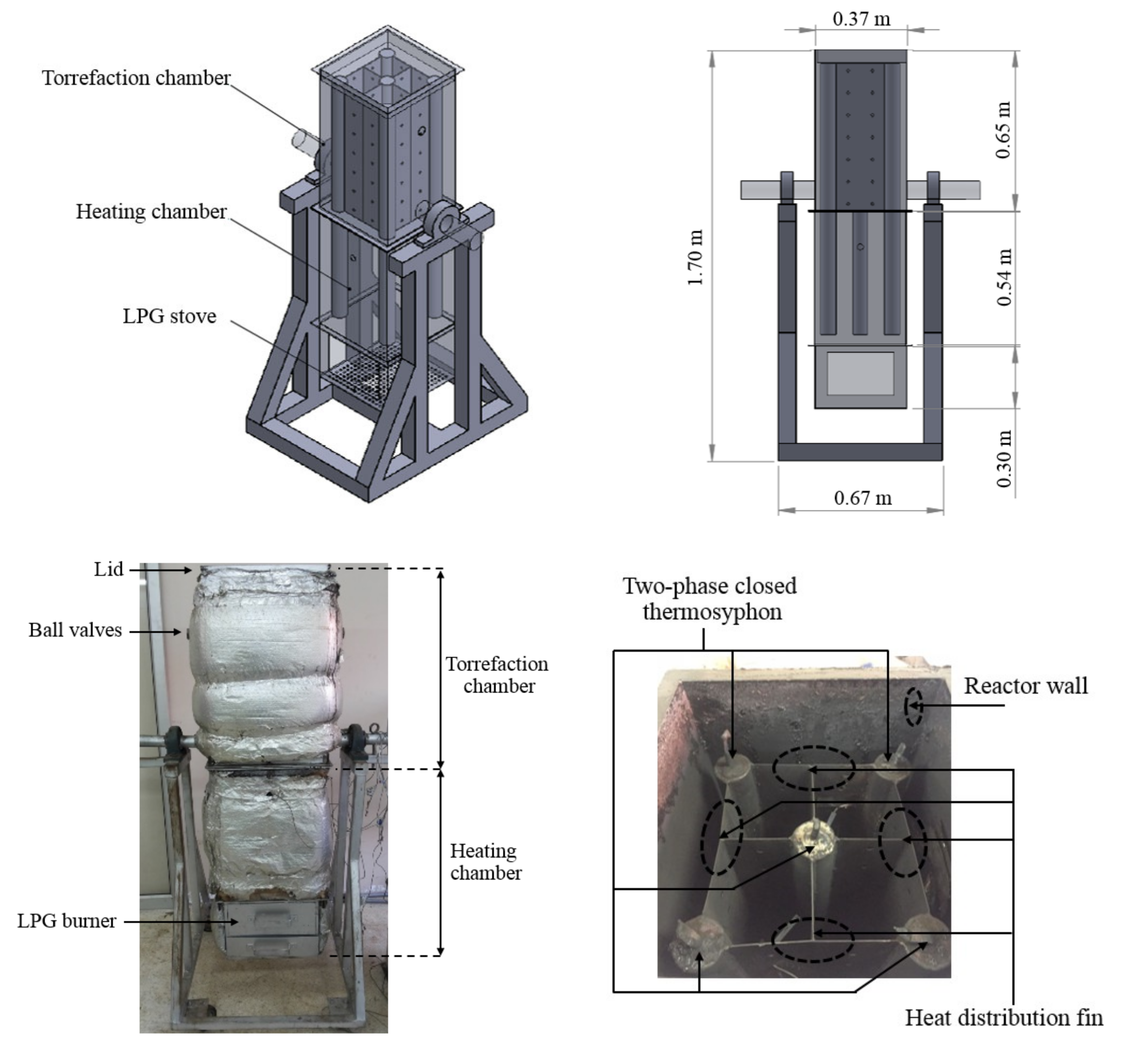
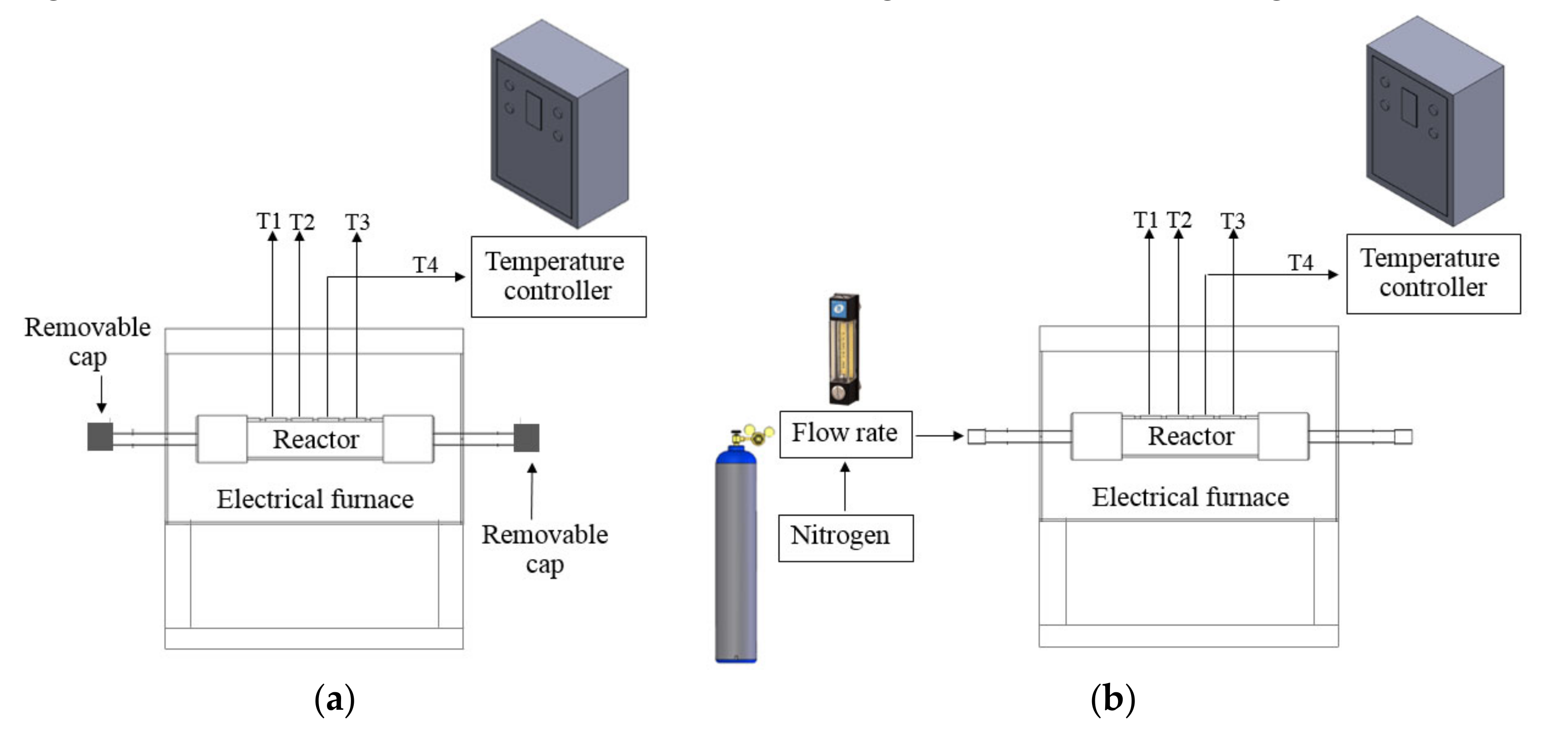
2.2. Thermosyphon - Fixed Bed Torrefaction Reactor

Figure 1 shows the thermosyphon-fixed bed torrefaction reactor (TSFR). The mild steel reactor had a width of 0.37 m, a length of 0.37 m and a height of 1.49 m. It was divided into two parts: the: torrefied chamber and the heating chamber. These two parts were completely separated by the steel plate at the bottom of the torrefied chamber. The length of the torrefied and heating chambers were 0.65 m and 0.84 m, respectively. The heating chamber was separated into two zones which were the thermosyphon’s evaporator zone (0.54 m) and the combustion zone (0.30 m). A liquefied petroleum gas burner, placed in the heating chamber, was used as a heat source. Heat was transferred from the heating chamber to the torrefied chamber by five two-phase closed thermosyphons installed inside the reactor (one in the middle and four at each corner of the torrefaction chamber). Each two-phase closed thermosyphon was made from mild steel pipe of 0.06 m outside diameter, 2.5 mm in thickness, and 1.10 m in length. The evaporator and condenser section were 0.50 m and 0.60 m, respectively. Dowtherm–A was used as the working fluid. The filling ratio was 50% of the evaporator volume.
The volatile produced from biomass torrefaction left the reactor via two vent tubes installed on the lateral surface of the reactor. Two ball valves were installed at the end of each vent tube to control the volatile ventilation. These valves were closed until the temperature of the biomass inside the reactor had reached the water boiling point. After that they were opened to release water vapor and volatile. When the torrefaction process had finished, both ball valves were closed, and the reactor was left to cool to room temperature. To observe the temperature distribution of the biomass inside the torrefied chamber, ten Type K thermocouples were installed at the heights of 0.94 m, 1.04 m, 1.14 m, 1.24 m and 1.34 m, measured from the bottom side of reactor. The surface temperature of the thermosyphon was also measured by installing six Type K thermocouples at the heights of 0.54 m, 0.84 m and 1.44 m. The details of the installation are shown in Figure 2.

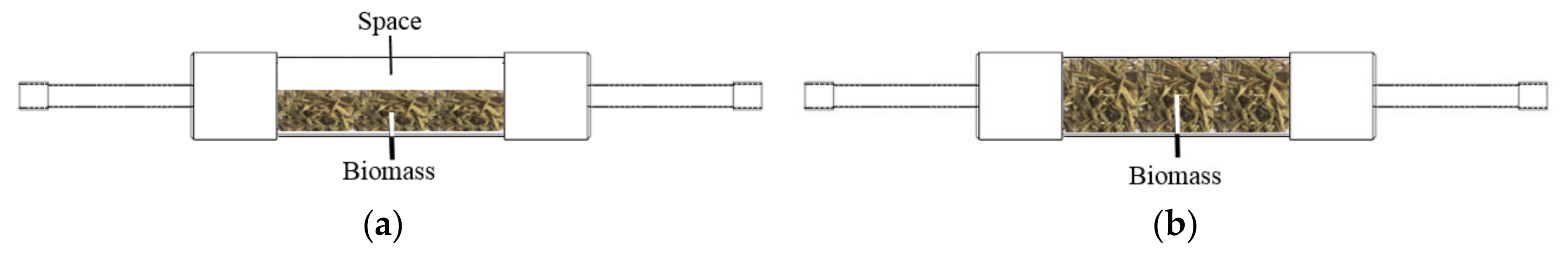
2.3. Laboratory fixed Bed Torrefaction Reactor

The laboratory-fixed bed torrefaction reactor was shown in Figure 3. It was made of a stainless steel cylinder, with a diameter of 0.04 m, and a thickness of 2.5 mm. The reactor length was 0.10 m. Heat was generated by a 3 kW electrical heater. Three Type K thermocouples were installed inside the reactor to observe the biomass temperature. The torrefaction was done in two ways: torrefaction without purge gas and torrefaction with nitrogen as the purge gas. For torrefaction without any purge gas, both ends of the reactor were closed during the heating period. When the biomass temperature reached the water boiling point, one end of the reactor was opened to release the water vapor and volatile matters from the reactor. For torrefaction with nitrogen, a flow rate of 100 mL/min was purged through the reactor. The volumetric flow rate of the nitrogen was controlled using a rotameter.

2.4. Experimental Procedure

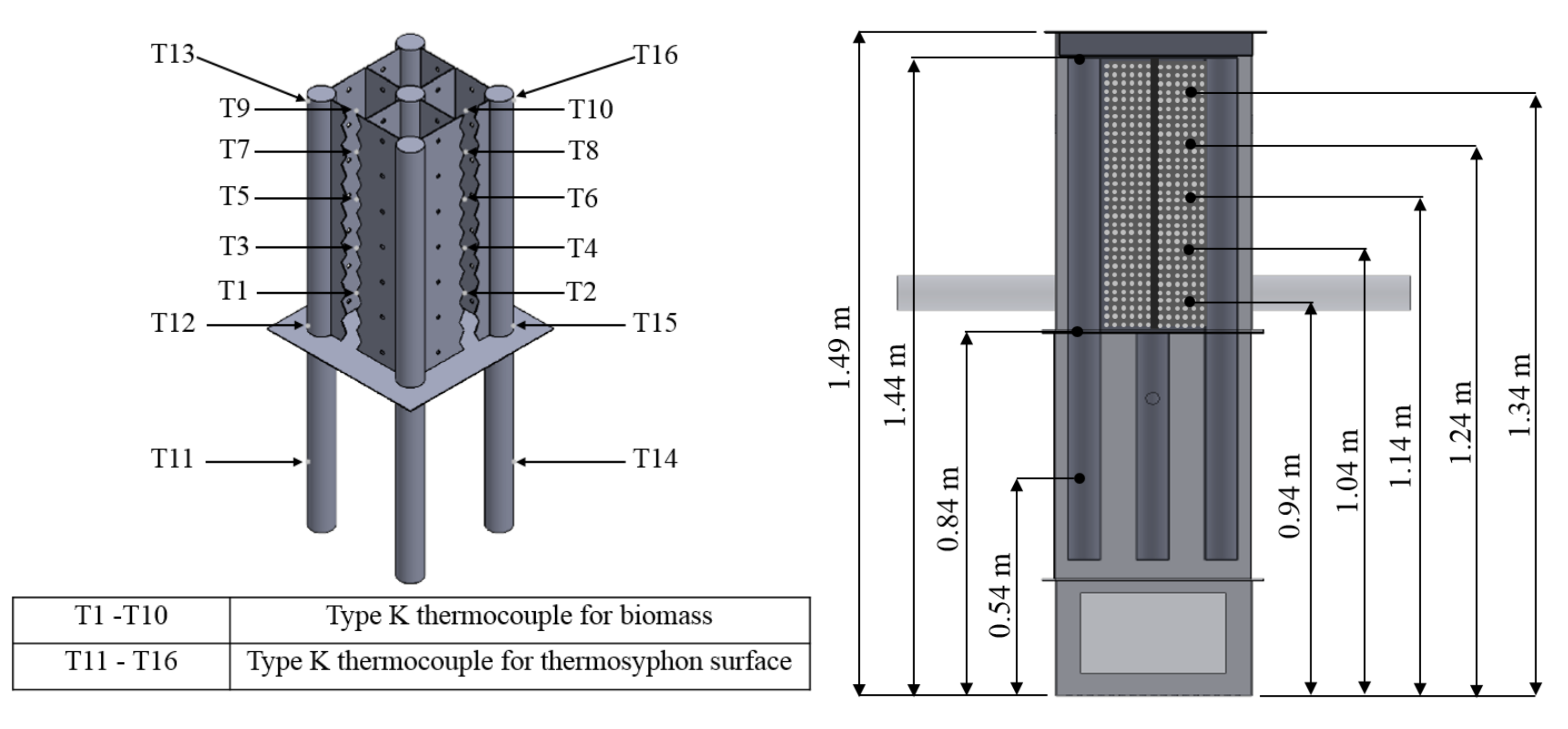
2.4.1. Temperature Distribution of Cassava Rhizome and Heating Rate

To investigate the temperature distribution of cassava rhizome inside TSFR, a sample of 4.45 kg was filled in the torrefied chamber. After that, the lid of the torrefied chamber was closed to prevent sample exposure from the outside air. The heating chamber temperature was controlled at 450 °C. The cassava rhizome temperatures measured from each thermocouple and heating time were recorded. Then, the graph between cassava rhizome temperatures and the height of the cassava rhizome bed was plotted. All cassava rhizome temperatures in the bed were averaged. This temperatures value was used to monitor the heating process as the biomass bed temperature, and to determine the heating rate to the bed. To investigate the effect of thermosyphons on heat distribution to the cassava rhizome bed, working fluid (Dowtherm–A) was removed from the thermosyphons of TSFR. Without working fluid inside the thermosyphon, TSFR became a fixed bed reactor with no thermosyphon. The experimental procedure for this case was similar to TSFR as described earlier.

2.4.2. Torrefied Char Preparation and Properties Analysis

To obtain the torrefied char from thermosyphon-fixed bed torrefaction reactor, 4.45 kg of cassava rhizome was used for each experiment. The heat was given to the reactor until it reached the set torrefied temperature. Then, the input heat was controlled to keep the torrefied temperature constant. When the desired torrefied time was reached, the reactor was left to cool to room temperature. This configuration was denoted as TSFR.
The obtained torrefied char was weighed and stored in closed plastic bags for further analysis. Torrefied char from the laboratory fixed bed torrefaction reactor was obtained from two different arrangements: the hollow and compact bulk arrangement, as shown in Figure 4. Regarding to purge gas usage, the configuration for the laboratory reactor can be divided into four types. The first and second ones were the hollow bulk arrangement with purge gas (N2) and without purge gas, which are denoted as LR-HN2 and LR-HW, respectively. The third and fourth ones were the compact bulk arrangement with purge gas (N2) and without purge gas, which are denoted as LR-CN2 and LR-CW, respectively. The cassava rhizomes of 13 g and 26 g were placed into the reactor for the hollow and compact bulk arrangements, respectively. The torrefied temperatures for both thermosyphon-fixed bed and laboratory-fixed bed reactor was set at 230 °C, 260 °C and 280 °C. For each temperature, the torrefied time was set at 1 hour after the torrefied temperature was reached.
The higher heating value of the torrefied char obtained from both reactors was measured using a bomb calorimeter in accordance with the ASTM D 5865-07a method. The mass and energy yield of this experiment was calculated using the following equation:
Y mass = m torrefied   char m raw   biomass
Y energy = Y mass × HHV torrefied   char HHV raw   biomass
where Ymass and Yenergy denoted the mass yield and energy yield, respectively. mtorrefied char and mraw biomass represented the mass of the torrefied char and the mass of raw biomass at the initial time (kg), respectively, and HHVtorrefied char and HHVraw biomass signified the higher heating value of the torrefied char and raw biomass (MJ/kg), respectively.
Scanning Electron Microscopy (SEM) was used to study the surface morphology of the torrefied char obtained from five configurations: TSFR, LR-CN2, LR-CW, LR-HN2 and LR-HW.

3. Results and Discussion

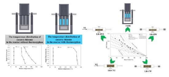
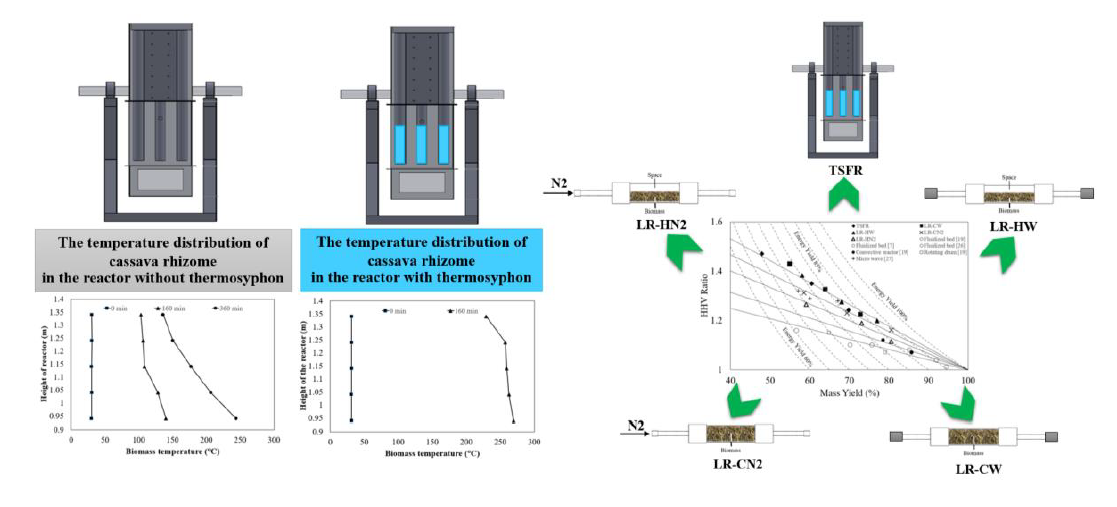
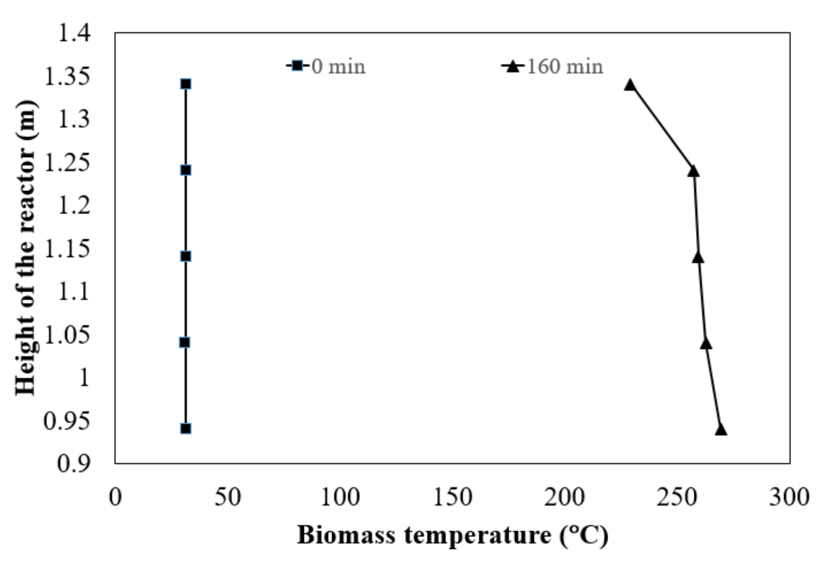
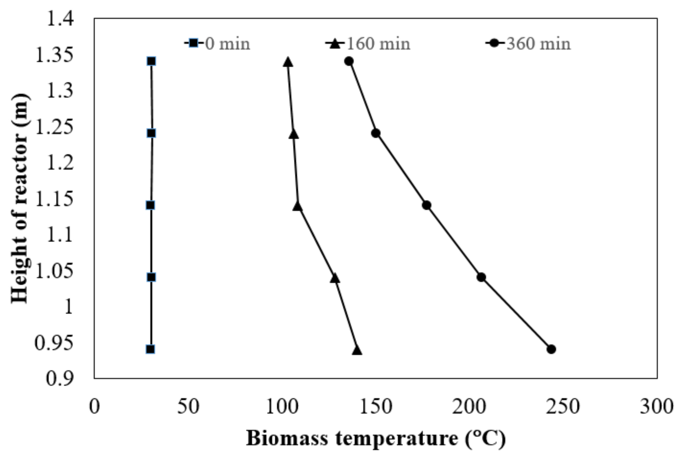
3.1. Temperature Distribution of Cassava Rhizome and Heating Rate

The temperature distribution of cassava rhizome inside the TSFR at the heating chamber temperature of 450 °C is shown in Figure 5. The vertical axis displays the height measured from the bottom of the reactor. It should be noted that the torrefied chamber was placed at the height of 0.84 m (the bottom) to 1.49 m (the top). At the heating time of 160 min, the temperature of this cassava rhizome increased from 31.4 °C to 269.3 °C at the bottom and 31.4 °C to 229.3° C at the top. The maximum temperature difference was 40.0 °C (equivalent to 14.85%, based on the maximum temperature at the same time of 269.3 °C). The average temperature of the cassava rhizome was 255.6 °C. The average heating rate to the cassava rhizome bed was 1.40 °C/min, which was quite low compared to the heating rate of the electrical heated fixed bed reactor reported by Budde et al. [21] (10 °C/min.). The moisture content of the biomass used in their work was less than 6%, while the biomass used in the present work contained 12% of moisture content.
The higher moisture content in the biomass resulted in a low heating rate. The temperature distribution in the case of the fixed bed reactor without thermosyphon is shown in Figure 6. At the similar heating time of 160 min, the temperature of cassava rhizome increased from 30.2 °C to 140.1 °C at the bottom and 30.3 °C to 103.0 °C at the top. The average temperature of cassava rhizome was 117.2 °C. The average heating rate was 0.54 °C/min. To achieve the set temperature of cassava rhizome (260 ± 10 °C), the heating chamber temperature was maintained at 450 °C until 360 min. At this time, the temperature at the bottom was 243.7 °C, while the one at the top was 136.0 °C. The temperature difference between the bottom and top was 107.7 °C. The average temperature of cassava rhizome was 182.7 °C, which deviated too far from the set point. These results indicated the change in heat transfer mechanism after the thermosyphons were installed. In the case of a fixed bed reactor without thermosyphons, the heat was transferred from the cassava rhizome at the bottom to the top by heat conduction. Due to the void between the cassava rhizome chips, the cassava rhizome bed was in a form of porous media, having high conductive thermal resistance. Thus, the high temperature gradient along the bed height occurred, and a very long heating time was needed to reach the set torrefied temperature, as seen in Figure 6. To control the properties of torrefied biomass, the torrefied temperature range should be narrow. Hence, it was not possible to use the conduction heat transfer mechanism through the thick biomass bed to conduct the torrefaction process. In the case of TSFR, the working fluid inside the thermosyphon received heat from the heating chamber in a form of latent heat, and transferred this heat through the thermosyphon’s condenser section located along the biomass bed height. With this heat transfer mechanism, the heat was transfered uniformly throughout the biomass bed, with low thermal resistance and a low temperature gradient along the bed height taking place, as seen in Figure 5. In addition, the average heating rate of the fixed bed thermosyphon reactor was 2.59 times higher than that of one without thermosyphons. This result confirmed that thermosyphons played an important role to reduce the total thermal resistance of the cassava rhizome bed. Because the order of magnitude of the thermosyphon’s internal thermal resistances were small compared to thermal resistance of the cassava rhizome bed, the height of the torrefied chamber can be increased. In other words, the fixed bed reactor went upscale with uniform heat distribution by using thermosyphons. Although the thermosyphons reduced the total thermal resistance of the bed, the heating rate of TSFR was low compared to the other types. The cause of its low heating rate was the high thermal resistance between the heat source and the thermosyphon’s evaporator. In this work, a steel tube without fin was used to produce the thermosyphon’s evaporator. This configuration resulted in high thermal resistance and a low heat transfer rate from the heat source to the evaporator. The use of extended surface at the evaporator to reduce the thermal resistance can increase the heating rate of the thermosyphon-fixed bed reactor. To achieve the optimum design and specify the heating rate range, further study on the thermal characteristic model of this reactor is required.
In conclusion, the use of thermosyphons with a fixed bed reactor improved the uniform temperature distribution. For the heating chamber temperature of 450 °C, the maximum temperature difference of cassava rhizome along the torrefied chamber height was 40.0 °C (equivalent to 14.85% based on the maximum temperature at the same time of 269.3 °C). The average heating rate to the cassava rhizome bed of TSFR was 1.40 °C/min, which was 2.59 times higher than that of the fixed bed reactor without thermosyphons.

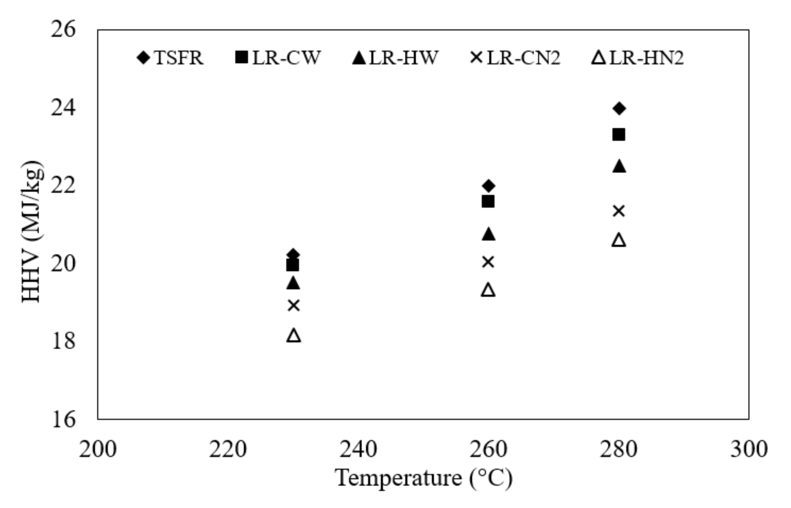
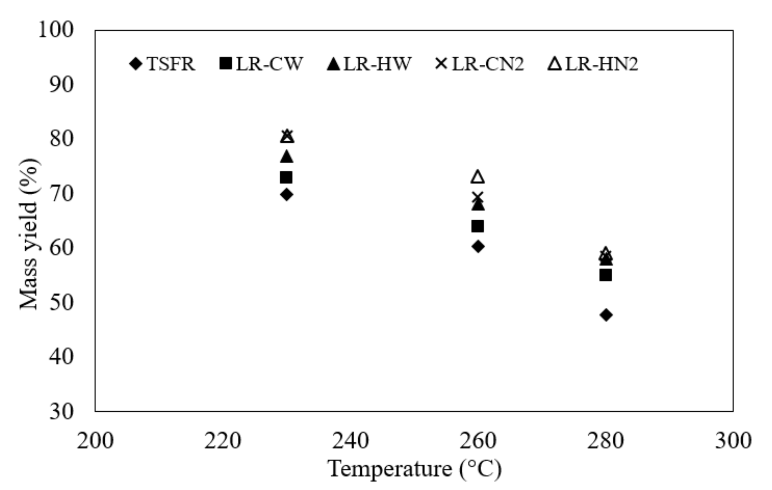
3.2. Comparison of Torrefied Char Properties
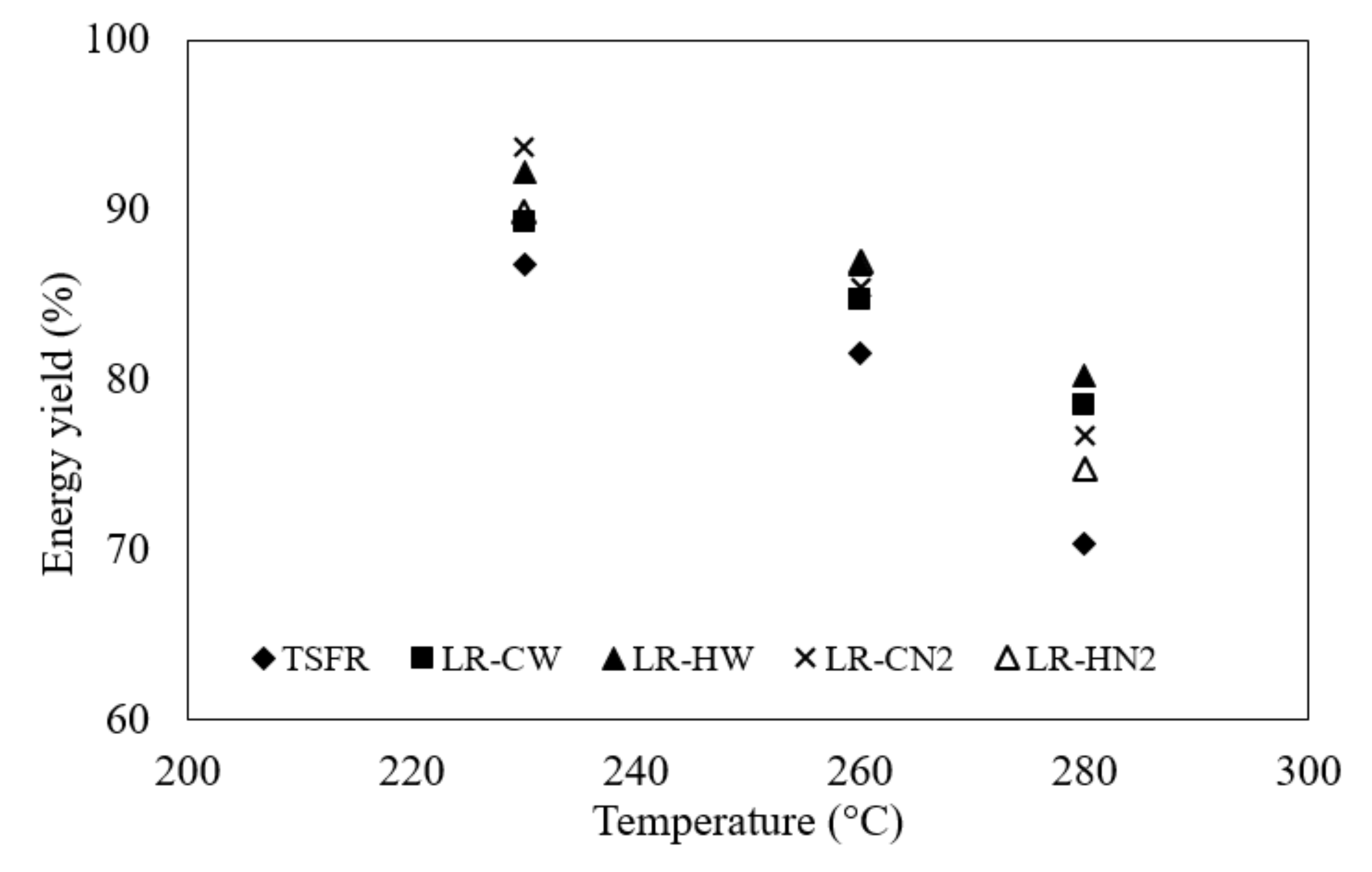
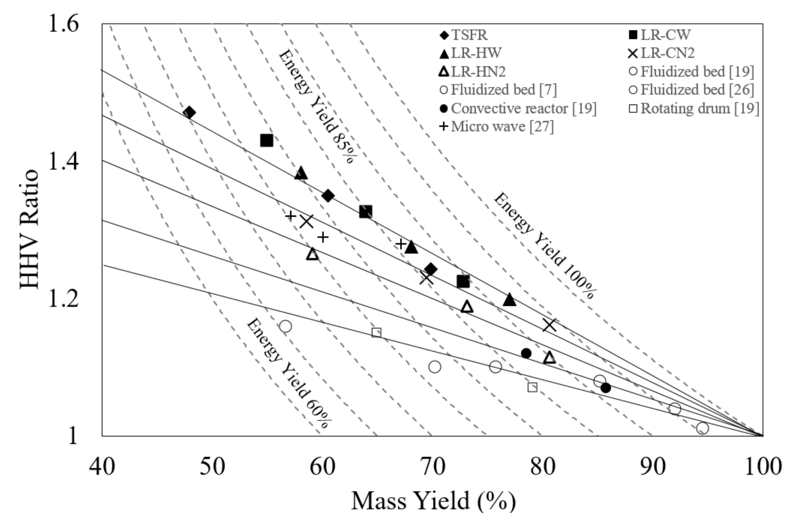
Figure 7 and Figure 8 show the HHV of torrefied char and mass yield at various torrefied temperatures. The HHV of raw cassava rhizome and char sample obtained from each configuration, the mass yield and energy yield, were shown in Table 2. For all configurations, the HHV tended to increase nonlinearly when the temperature was increased. The torrefied char obtained from TSFR gave the highest HHV and the lowest mass yield for all temperature. The second and third ranks were samples obtained from LR-CW and LR-HW, respectively. LR-CN2 and LR-HN2 gave the lower HHV and the higher mass yield comparing with the previous configurations.
These results indicated the effect of purge gas on the thermal decomposition of cassava rhizome, which can be explained as follows. Mok et al. [22] reported that the water vapor, produced from biomass pyrolysis, played a role as an autocatalyst for the cellulose degradation reaction, and the increases of water vapor concentration in the reactor conducted the decrease of the reaction onset temperature. In this study, when N2 flowed through the reactor, the vapor produced from the thermal decomposition of cassava rhizome was purged, resulting in the decrease of water vapor concentration. Therefore, the reaction onset temperature for torrefaction with N2 as the purge gas was higher than that for the others. According to previous work [22], the reaction onset temperature of cellulose with 12.1% moisture content was about 285 °C. When comparing with the temperature range in this experiment (230 °C–280 °C), it was seen that the cellulose content of cassava rhizome was insignificantly decomposed. It was known that any lower degree of decomposition resulted in lower HHV [15,18]. Hence, purging the vapor product with N2 gas contributed the lower HHV and mass yield. In other words, torrafaction without purge gas caused the high water vapor concentration. Water vapor was able to act as an efficient catalyst. In the case of TSFR, LR-CW and LR-HW, the higher heating value and lower mass yield were obtained (Figure 7 and Figure 8). Moreover, the HHV and mass yield of torrefied char obtained from both arrangements were different. The compact bulk arrangement showed the higher value of HHV and lower value of the mass yield compared with the hollow bulk one. These results can be explained by considering the resident time of the degradation reaction with a water vapor catalyst. In the case of a compact bulk arrangement, the reactor was fulfilled with cassava rhizome. The water vapor, produced from torrefaction, uniformly contacted with the surface of cassava rhizome, and gradually passed through the cassava rhizome bed before leaving the reactor, resulting in a long resident time for water vapor as a catalyst. In contrast, there was space above the bed in the case of a hollow bulk arrangement (Figure 4). It was easier for water vapor to flow through the bed to this space before leaving the reactor, rather than flowing through the bed in the longitudinal axis of the reactor. This flow direction conducted a short time for water vapor to contact with the biomass surface, and water vapor inefficiently catalyzed the reaction. Therefore, the decomposition degree in the hollow bulk arrangement was lower than that of the compact bulk one. When the decomposition degree was lower, the mass yield was lower while HHV was higher. In the case of TSFR, it had a larger size and more biomass loading compared with that of the laboratory reactor. The resident time of water vapor before leaving the reactor was also longest. Therefore, its decomposition degree was also highest. The lowest mass yield and the highest HHV were seen in this case. It was clear that the use of purge gas and arrangement both affected the mass yield and the HHV. Nevertheless, the use of purge gas had a stronger effect than the arrangement. The evidence was made up of SEM images, as shown in Figure 9. The SEM image obtained from TSFR displayed the highest degree of decomposition. The outer layer was destroyed, and the inner layer and small holes on this layer were clearly seen (Figure 9a). For the SEM image obtained from LR-CW, the inner layer and small holes were still fully visible. However, a trace of the substrate of the outer layer can be slightly seen (Figure 9b). It indicated a lower decomposition degree compared that of the TSFR. The outer layer can be clearly seen in the SEM image obtained from LR-HW. Small holes on inner surface cannot be seen due to a covering of the outer layer substrate (Figure 9c). This covering indicated the lowest decomposition degree among three configurations which torrefied without using purge gas. There was a similarity between Figure 9c,d, which SEM image was obtained from LR-CN2. This similarity indicated the same decomposition degree, resulting in an insignificant difference of mass yield, as seen in Figure 9. The morphology of the outer layer was clearly seen for the SEM image obtained from LR-HN2 (Figure 9e), indicating the lowest degree of decomposition.
It can be concluded that TSFR contributed the highest HHV and the lowest mass yield, compared to the other configurations. The highest HHV was 23.97 MJ/kg, and the lowest mass yield was 47.84%, where both values were found from torrefied temperature of 280 °C. The water vapor, produced from torrefaction, played an important role as an autocatalyst, which was similar to LR-CW. The resident time for water vapor to catalyze was also an important parameter when the large size of reactor and biomass were used.

3.3. Energy Yield

Figure 10 shows the relationship between torrefied temperature and energy yield. The TSFR gave an energy yield of 86.86%, 81.60% and 70.43% when the torrefied temperature was 230 °C, 260 °C and 280 °C, respectively. The energy yield for the other configurations is shown in Table 1. For all configurations, energy yield tended to decrease when torrefied temperature was increased. Energy yields obtained in this work and the previous ones were in the same range [23,24,25]. To decide the most suitable torrefied condition and configuration regarding to energy yield, the data obtained in the present work and the data reported by the previous works on the fluidized bed reactor [7,19,26], rotating drum reactor [19], convective reactor [19] and microwave reactor [27], were replotted in the HHV ratio-mass yield diagram, as shown in Figure 11. The HHV ratio was defined as the ratio of HHV of torrefied char to HHV of raw biomass. According to the definition of energy yield, the iso-energy yield line can also be plotted on this diagram, which consisted of two points of discussion, as follows. Firstly, there was a difference on mass loss characteristic during torrefaction with different configuration. The detail was explained as follows. It was known that the decrease of mass yield without the change of HHV means only that moisture was released from biomass.
The increase of HHV along with the decrease of mass yield indicated the decomposition of a chemical bond and a change in molecular structure. Therefore, a low degree of decomposition caused the low slope of the HHV ratio–mass yield graph. In contrast, the high slope pointed to a high degree of decomposition. In addition, if there is only one decomposition mechanism during torrefaction, one value of HHV will be obtained from one specific mass yield, and there is only one slope on the plot. However, Figure 11 shows a contrast. The difference in slope showed the difference in decomposition pathways. Five linear trend lines were found in Figure 11. The line with highest slope belonged to the data group obtained from LR-CW, LR-HW and TSFR, all of which were without purge gas. The two lines with medium slope were obtained from LR-CN2 and LR-HN2, respectively. The data of the microwave reactor [27] was on a same linear line of LR-CN2. The two lines with the lowest slope were obtained from the data of convective reactor [19], fluidized bed reactor [7,19,26] and rotating drum reactor [19]. It was clearly seen that there were five decomposition pathways depending on torrefied configuration. Five solid lines in Figure 11 were used to represent the change of HHV ratio for each torrefied configuration; in other words, decomposition pathway. These solid lines indicated one to one mapping between HHV ratio and energy yield for each particular decomposition pathway. The top solid line showed that torrefaction without purge gas resulted in the highest HHV ratio at the similar energy yield.
Secondly, there were many values of HHV ratio at the similar energy yield depending on the decomposition pathway (Figure 11). Thus, the most suitable torrefied condition and configuration should be identified by the criteria of the highest HHV ratio at the similar energy yield. When consideration was done on each iso-energy yield line, the highest HHV ratio was found on the top solid line which represented group of torrefaction without purge gas including TSFR, LR-CW and LR-HW. When TSFR was designed to solve a scaleup problem, it was the most suitable configuration which contributed the highest HHV ratio at the same energy yield. In addition, TSFR produced torrefied biomass with the highest HHV ratio compared to those of fluidized bed reactor, rotating drum reactor, convective reactor and microwave reactor at the same energy yield.
In conclusion, TSFR gave an energy yield in range of 70.43% to 86.68%. The plot of HHV ratio–mass yield diagram indicated three data groups of different decomposition pathway. In terms of scaleup, TSFR was the most suitable configuration in this work.

4. Conclusions

Thermosyphon-fixed bed reactor (TSFR) was designed and constructed in this work to investigate the temperature distribution of biomass and its decomposition behavior. Torrefaction of cassava rhizome with TSFR and four torrefied configurations were conducted. It was found that thermosyphons improved the uniform temperature distribution inside a cassava rhizome bed. The average heating rate to the cassava rhizome bed of TSFR was higher than that of fixed bed reactor without thermosyphons. Compared to the other configurations, TSFR contributed the highest HHV and the lowest mass yield of 23.97 MJ/kg and 47.84%, respectively. The water vapor played an autocatalyst role, which was also found in the compact bulk arrangement. The resident time for catalyzation was also an important parameter when the large size of reactor was used. Finally, TSFR gave an energy yield in range of 70.43% to 86.68%. The plot of HHV ratio-mass yield diagram indicated three data groups of different decomposition pathways. TSFR was the most suitable configuration regarding to the iso-energy yield criteria. The obtained results indicated the TSFR had a simple structure and had no moving part. Thus, TSFR had a low construction cost. In addition, it could be operated easily, and did not need electricity for operation. Although TSFR gave a low heating rate, it produced torrefied biomass with the highest HHV ratio compared that obtained from other types of the reactor at the same energy yield. These advantages indicated that TSFR was suitable to use in a rural area in which the electricity was costly and the complicated control process should be avoided. However, there is a question on the energy efficiency of TSFR. Further study on specific energy consumption of TSFR is needed.

Author Contributions

Conceptualization, N.S. and S.N.; Methodology, N.S., S.N. and P.C.; Software, N.S.; Validation, N.S., S.N. and P.C.; Formal Analysis, N.S.; Investigation, N.S., S.N. and P.C.; Resources, N.S., S.N. and P.C.; Data Curation, N.S., S.N. and P.C.; Writing—Original Draft Preparation, N.S., S.N. and P.C.; Writing—Review and Editing, N.S., S.N. and P.C.; Visualization, N.S. and S.N.; Supervision, S.N. and P.C.; Project Administration, N.S., S.N. and P.C.; Funding Acquisition, S.N. and P.C. All authors have read and agreed to the published version of the manuscript.

Funding

This research was funded by Silpakorn University Research, Innovation and Creative Fund, grant number RD59M2-16.

Acknowledgments

The authors gratefully acknowledge Silpakorn University Research, Innovation and Creative Fund and Department of Mechanical Engineering, Faculty of Engineering and Industrial Technology, Silpakorn University, Sanam Chandra Palace Campus for all supports.

Conflicts of Interest

The authors declare no conflict of interest.

References

  1. Medic, D.; Darr, M.; Shah, A.; Potter, B.; Zimmerman, J. Effects of torrefaction process parameters on biomass feedstock upgrading. Fuel 2012, 91, 147–154. [Google Scholar] [CrossRef]
  2. Deng, J.; Wang, G.-J.; Kuang, J.-H.; Zhang, Y.-L.; Luo, Y.-H. Pretreatment of agricultural residues for co-gasification via torrefaction. J. Anal. Appl. Pyrolysis 2009, 86, 331–337. [Google Scholar] [CrossRef]
  3. Bridgeman, T.G.; Jones, J.M.; Shield, I.; Williams, P.T. Torrefaction of reed canary grass, wheat straw and willow to enhance solid fuel qualities and combustion properties. Fuel 2008, 87, 844–866. [Google Scholar] [CrossRef]
  4. Pimchuai, A.; Dutta, A.; Basu, P. Torrefaction of agriculture residue to enhance combustible properties. Energy Fuels 2010, 24, 4638–4645. [Google Scholar] [CrossRef]
  5. Arias, B.; Pevida, C.; Fermoso, J.; Plaza, M.G.; Rubiera, F.; Pis, J.J. Influence of torrefaction on the grindability and reactivity of woody biomass. Fuel Process. Technol. 2008, 89, 169–175. [Google Scholar] [CrossRef] [Green Version]
  6. Felfli, F.F.; Luengo, C.A.; Suárez, J.A.; Beaton, P.A. Wood briquette torrefaction. Energy Sustain. Dev. 2005, 9, 19–22. [Google Scholar] [CrossRef]
  7. Li, H.; Liu, X.; Legros, R.; Bi, X.T.; Lim, C.J.; Sokhansanj, S. Torrefaction of sawdust in a fluidized bed reactor. Bioresour. Technol. 2012, 103, 453–458. [Google Scholar] [CrossRef]
  8. Wannapeera, J.; Fungtammasan, B.; Worasuwannarak, N. Effects of Temperature and holding time during torrefaction on the pyrolysis behaviors of woody biomass. J. Anal. Appl. Pyrolysis 2011, 92, 99–105. [Google Scholar] [CrossRef]
  9. Sabil, K.M.; Aziz, M.A.; Lal, B.; Uemura, Y. Effects of torrefaction on the physiochemical properties of oil palm empty fruit bunches mesocarp fiber and kernel shell. Biomass Bioenergy 2013, 56, 351–360. [Google Scholar] [CrossRef]
  10. Phanphanich, M.; Mani, S. Impact of torrefaction on the grindability and fuel characteristics of forest biomass. Bioresour. Technol. 2011, 102, 1246–1253. [Google Scholar] [CrossRef]
  11. Prins, M.J.; Ptasinski, K.J.; Janssen, F.J.J.G. Torrefaction of wood: Part 2. Analysis of products. J. Anal. Appl. Pyrolysis 2006, 77, 35–40. [Google Scholar] [CrossRef]
  12. Acharjee, T.C.; Coronella, C.J.; Vasquez, V.R. Effect of thermal pretreatment on equilibrium moisture content of lignocellulosic biomass. Bioresour. Technol. 2011, 102, 4849–4854. [Google Scholar] [CrossRef] [PubMed]
  13. Bridgeman, T.G.; Jone, J.M.; Williams, A.; Waldron, D.J. An investigation of the grindability of two torrefied energy crops. Fuel 2010, 89, 3911–3918. [Google Scholar] [CrossRef] [Green Version]
  14. Chen, W.-H.; Cheng, W.-Y.; Lu, K.-M.; Huang, Y.-P. An evaluation on improvement of pulverized biomass property for solid fuel through torrefaction. Appl. Energy 2011, 88, 3636–3644. [Google Scholar] [CrossRef]
  15. Chen, W.-H.; Huang, M.-Y.; Chang, J.-S.; Chen, C.Y. Thermal decomposition dynamics and severity of microalgae residues in torrefaction. Bioresour. Technol. 2014, 169, 258–264. [Google Scholar] [CrossRef]
  16. Guo, J.; Lua, A.C. Kinetic study on pyrolysis of extracted oil palm fiber: Isothermal and non-isothermal conditions. J. Therm. Anal. Calorim. 2000, 59, 763–774. [Google Scholar] [CrossRef]
  17. Guo, J.; Lua, A.C. Kinetic study on pyrolytic process of oil-palm solid waste using two-step consecutive reaction model. Biomass Bioenergy 2001, 20, 223–233. [Google Scholar] [CrossRef]
  18. Soponpongpipat, N.; Sae-Ueng, U. The effect of biomass bulk arrangements on the decomposition pathways in the torrefaction process. Renew. Energy 2015, 81, 679–684. [Google Scholar] [CrossRef]
  19. Dhungana, A.; Basu, P.; Dutta, A. Effects of Reactor Design on the Torrefaction of Biomass. J. Energy Resour. Technol. 2012, 134, 041801. [Google Scholar] [CrossRef]
  20. Department of Alternative Energy Development and Efficiency, Ministry of Energy. Available online: https://www.dede.go.th/ewt_news.php?nid=486 (accessed on 19 February 2020).
  21. Budde, K.P.; Megha, R.; Patel, R.; Pandey, J. Investigating effects of temperature on fuel properties of torrefied biomass for bio-energy systems. Energy Sources Part A 2018, 41, 1140–1148. [Google Scholar] [CrossRef]
  22. Mok, W.S.L.; Antal, M.J.; Szabo, P.; Varhegyi, G.; Zelei, B. Formation of charcoal from biomass in a sealed reactor. Ind. Eng. Chem. Res. 1992, 31, 1162–1166. [Google Scholar] [CrossRef]
  23. Wannapeera, J.; Worasuwannarak, N. Examinations of chemical properties and pyrolysis behaviors of torrefied woody biomass prepared at the same torrefaction mass yields. J. Anal. Appl. Pyrolysis 2015, 115, 279–287. [Google Scholar] [CrossRef]
  24. Ahiduzzaman, M.D.; Islam, A.K.M.S. Energy Yield of Torrefied Rice Husk at Atmospheric Condition. Procedia Eng. 2015, 105, 719–724. [Google Scholar] [CrossRef] [Green Version]
  25. Zhang, Y.; Song, K. Thermal and chemical characteristics of torrefied biomass derived from a generated volatile atmosphere. Energy 2018, 165, 235–245. [Google Scholar] [CrossRef]
  26. Atienza-Martínez, M.; Fonts, I.; Ábrego, J.; Ceamanos, J.; Gea, G. Sewage sludge torrefaction in a fluidized bed reactor. Chem. Eng. J. 2013, 222, 534–545. [Google Scholar] [CrossRef]
  27. Lin, Y.L. Effects of Microwave—Induced Torrefaction on Waste Straw Upgrading. Int. J. Chem. Eng. Appl. 2015, 6, 401–404. [Google Scholar] [CrossRef] [Green Version]
Figure 1. Thermosyphon-fixed bed torrefaction reactor.
Processes 08 00267 g001
Figure 2. Detail of thermocouples installation.
Processes 08 00267 g002
Figure 3. Laboratory-fixed bed torrefaction reactor. (a) Torrefaction without purge gas; (b) Torrefaction with nitrogen as purge gas.
Processes 08 00267 g003
Figure 4. Two types of biomass bulk arrangement. (a) Hollow bulk arrangement; (b) Compact bulk arrangement.
Processes 08 00267 g004
Figure 5. The temperature distribution of cassava rhizome in the reactor with thermosyphon at heating chamber temperature of 450 °C.
Processes 08 00267 g005
Figure 6. The temperature distribution of cassava rhizome in the reactor without thermosiphon at heating chamber temperature of 450 °C.
Processes 08 00267 g006
Figure 7. The relationship between the higher heating value (HHV) and torrefied temperature.
Processes 08 00267 g007
Figure 8. The relationship between mass yield and torrefied temperature.
Processes 08 00267 g008
Figure 9. Scanning electron microscopy (SEM) images of torrefied char at temperature of 260 °C (a) TSFR (b) LR-CW (c) LR-HW (d) LR-CN2 (e) LR-HN2.
Processes 08 00267 g009
Figure 10. The relationship between torrefied temperature and energy yield.
Processes 08 00267 g010
Figure 11. The plot of HHV ratio - mass yield diagram and iso-energy yield contour.
Processes 08 00267 g011
Table 1. Comparison of each reactor.
Reactor TypeHeating Medium/Heat SourceSize of Heat Transfer Surface Area of ReactorDifficulty to Operate the ProcessMoving or Special ElementLimitation to Scale Up
Direct heating reactor
1. Fixed bed Flue gas, Inert gas, or Superheated steamN/AHardInert gas heat exchanger or superheated steam generator, Inert gas compressor- Nonuniform heat distribution, when the thickness of the biomass bed is high
- Difficulty to control the oxygen amount in flue gases
- Price of inert gas
- High construction cost for superheated steam generator
2. Rotating drumFlue gas or Superheated steamN/AHardDrum and driver set, superheated steam generator- High construction cost for the superheated steam generator and the reactor
- Difficulty to control the oxygen amount in the flue gases
3. Fluidized bedSolid medium and/or inert gasN/AVery hardGas/Air compressor, biomass/solid medium separator, - Biomass/solid medium separation
- High construction cost for peripheral equipment, such as the air/gas compressor and particle separator
- Price of inert gas
4. Moving bedFlue gas or superheated steamN/AHardConveyor belt- High construction cost for the superheated steam generator and the reactor
- Difficulty to control the oxygen amount in flue gases
5. Microwave MicrowaveN/AHardMicrowave generator- High construction cost for the reactor
- High energy consumption
Indirect heating reactor
1. Fixed bedCombustion or electrical heaterLargeEasyNo moving part- Nonuniform heat distribution when the thickness of the biomass bed is high
2. ScrewCombustion or electrical heaterLargeMediumScrew and its driver set- Nonuniform heat distribution when the thickness of the biomass bed is high
3. Rotating drumCombustion or electrical heaterLargeMediumDrum and its driver set- Nonuniform heat distribution when the thickness of the biomass bed is high
4. New reactor design in present workCombustionSmallEasyNo moving part- Uniform heat distribution when the thickness of the biomass bed is high, and low construction cost
Table 2. The properties of raw cassava rhizome and torrefied char obtained from each reactor.
ReactorTorrefied Temperature (°C)HHV (MJ/kg)Mass Yield (%)Energy Yield (%)
Raw cassava rhizome-16.29100100
Thermosyphon-fixed bed reactor (TSFR)23020.2469.8986.86
26021.9960.4381.60
28023.9747.8470.43
Laboratory reactor with compact bulk arrangement and without purge gas (LR-CW)23019.9672.8989.34
26021.5863.9684.76
28023.2954.9678.59
Laboratory reactor with hollow bulk arrangement and without purge gas (LR-HW)23019.5376.9692.28
26020.7868.0786.86
28022.5258.0880.32
Laboratory reactor with compact bulk arrangement and N2 purge gas (LR-CN2)23018.9380.5893.67
26020.0569.3885.41
28021.3758.5076.75
Laboratory reactor with hollow bulk arrangement and N2 purge gas (LR-HN2)23018.1680.6289.91
26019.3573.1586.92
28020.6259.0874.79

