1. Introduction
Exchanging heat between cold and hot process streams through heat exchangers is an effective form of waste heat recovery. A great many of researches have been undertaken, such as the optimization design of heat exchanger, and the synthesis of heat exchanger networks. For the optimization design of heat exchanger, the nanomaterials were mixed in the pure fluid since the nanoparticles have higher thermal conductivity and can give greater characteristics of carrier fluid [
1]. In addition, the turbulent flow of nanofluid in a pipe has been modeled in order to reach better design in view of second law [
2]. Also, the researches on heat exchanger network (HEN) synthesis have received considerable development, and still bolstered by new ideas. Mathematical programming approach based on superstructure is one of the most widely used methods for HEN synthesis. In recent years, the original stage-wise superstructure proposed by Yee and Grossmann [
3] has been improved and perfected. Such as the assumption of isothermal mixing was shattered [
4], and the superstructure was enhanced to contain more possibilities [
5], as well as to consider the parallel connection of utilities in stream split branches [
6] and series connection of utilities in substages [
7].
Absorption refrigeration cycle (ARC) is a high-efficiency energy cycle for heat recovery from middle- and low-temperature heat sources in term of generating cooling energy, and many researches have been conducted [
8,
9]. For greater energy-saving potential, some studies have also been launched on the integration of ARC with HEN. Ponce-Ortega et al. [
10] investigated the combination of ARC and HEN by using Pinch-based and mathematical programming methods, which can recycle heat below the pinch point for refrigerating. Lira et al. [
11] presented a superstructure having heat exchange system combined with solar absorption refrigeration system, for the sake of reaching the optimal configuration of the whole system, but the placement of generation process of ARC and the selection of evaporation temperature were not well investigated. This work was later extended by taking Organic Rankine Cycle into consideration for process heat recovery in 2014 [
12], but the ARC was still supposed to work at certain conditions rather than its optimal interior behavior accompanying with the system synthesis.
Although ARC is an effective technology, it cannot achieve a very low evaporation temperature [
13], and the energy efficiency drops quickly with decreasing evaporation temperature and generation temperature [
14,
15]. By contrast, the electrical compression refrigeration (ECR) can reach much lower refrigerating temperature and usually has higher efficiency, whereas consuming expensive electricity [
16]. Compression–absorption cascade refrigeration system (CACRS) retains the advantages of both ARC and ECR, as being able to achieve lower evaporation temperature with relatively high efficiency and less electricity consumption by recovering waste heat [
17].
In last several years, the increasing researches on CACRS have been reported. Some studies investigated the optimal selection and combination of working fluids so that better performance can be achieved. Cimsit et al. [
18] and Colorado et al. [
19] made a thermodynamic analysis and comparison of the CACRS with various couples of working fluids in the absorption and vapor compression sections. According to the study, the highest performance was associated with the R134a–LiBr/H
2O based system. The earlier literature studies dealing with the performance improvement of CACRS are mainly investigated based on the first and second laws, such as Cimsit et al. [
20]. Subsequently, the economic factor was taken into consideration in Cimsit’s study [
21], the exergy-based thermoeconomic analyses has been carried out and the best operating conditions can be determined with exergetic efficiency and minimum cost as objectives. The structural development of CACRS is also involved in relevant studies. Jain et al. [
22] and Xu et al. [
23] proposed the configurations of combined series-parallel and with evaporator-subcooler for cascade refrigeration system respectively and the energetic, exergetic, economic, and environmental analyses were conducted on different configurations.
In addition to above, some attention has been also concentrated to the optimal design of CACRS, in which parametric analysis on design variables are of great significance in pointing the direction for system design and optimization. According to Jain et al. [
24], the change of operating temperatures contributes to significant changes in overall system performance. Jain et al. [
25] established the model of CACRS, the effect of operating condition on the evaluation indicators are analyzed, based on which the study is extended to system optimization and design covering thermal and economical aspects [
26]. Considering the conflict between maximizing exergetic efficiency and minimizing total cost rate, multi-objective optimization of CACRS is performed by Aminyavari et al. [
27]. And the multi-objective optimization problem is solved with NSGA-II technique by Jain et al. [
28].
As mentioned, previous researches only focused on the incorporation of ARC with HEN for heat recovery while without optimizing operating condition, and the coefficient of performance (COP) of ARC was also assumed to be constant. Considering that CACRS combines the advantages of ARC and ECR, it is meaningful to integrate HEN with CACRS, however no study has been launched. Therein, considering the coupling relationship between HEN and CACRS, the operating condition of CACRS will significantly affect the structure of HEN and the performance ( for the absorption subsystem and for the compression subsystem are used as indicators to evaluate the performance) of CACRS. Therefore, in this paper, CACRS and HEN are considered as a whole system to recover heat for refrigeration, where the operating parameters and COPs of CACRS and the structure of HEN are optimized simultaneously.
The challenge of HEN synthesis with CACRS integrated is how to describe the coupling relationship between HEN and CACRS quantitatively, for which the COPs affected by operating condition are the crucial parameters to quantify the relationship. This paper handles the problem by means of discretizing the evaporation temperatures of two subsystems. At each evaporation temperature, the quantitative relationships between and heat source temperature, the quantitative relationships between and condensation temperature, are both obtained by simulating and data fitting. Therefore, the CACRS can be integrated into HEN in the form of a more detailed mathematic formulation. With this method, the optimal integrated system can be obtained with better performance and higher energy efficiency, large amount of excess heat can be recovered to minimize the economic cost.
This paper is organized as follows. The problem to be addressed in this paper is stated as
Section 2. The simulation and model formulation are conducted in
Section 3, wherein the two subsystems of CACRS are simulated, and the quantitative relationship between COPs and the operating variables of CACRS is determined with the simulation results, and the synthesis method for HEN integrated with CACRS is presented, which includes the superstructure composed of plentiful network alternatives and the detailed mathematical description for optimization purpose. The proposed method is demonstrated through two case studies in
Section 4, and the discussion is presented in
Section 5. Finally, conclusions are drawn in
Section 6.
2. Problem Statement
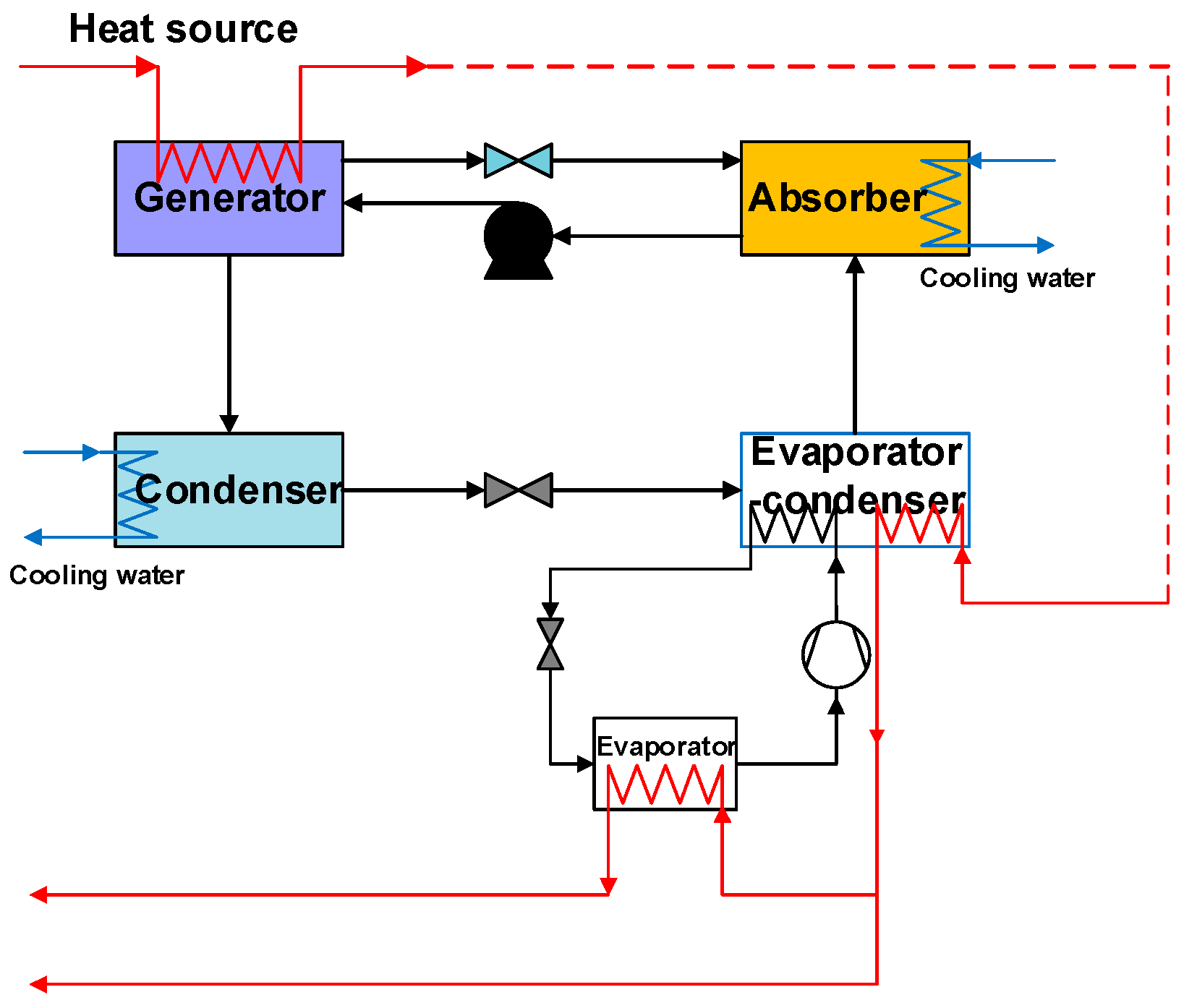
Figure 1 shows the schematic representation of the CACRS synthesized with heat source. The system is composed of an absorption subsystem and a single stage electrical compression subsystem. These two subsystems share a heat exchanger which operates as the evaporator of absorption section meanwhile the condenser of compression section simultaneously. The generator of absorption subsystem is heated by heat sources either waste heat of hot process streams or external steam, and the evaporators of two subsystems provide process streams with cooling energy. The absorber and condenser are cooled down with cooling water. Here it should be noted that, when the required refrigerating temperature, lower than room temperature while no less than 0 °C, can be achieved by the evaporator of absorption subsystem, electrical compression subsystem is not needed any more. When the refrigerating temperature is too low to be achieved by ARC, below 0 °C, the demand of refrigeration is satisfied by compression subsystem’s evaporation process of CACRS.
The COPs are crucial parameters to establish the relationship between the cold energy requirements in the evaporator and heat required by the generator (or the electricity consumed by the compressor). The mathematical expressions of
for ARC and
for ECR are in Equations (1) and (2), respectively. Whereas,
and
are reflected by the operating condition of ARC and ECR subsystems. Thus, in addition to exploring the structural integration of HEN and CACRS (or ARC or ECR if only one subsystem left), the COP related operational parameters, are also optimized with in this study.
The synthesis problem to be addressed in this paper can be stated as follows.
A set of hot process streams (some are below room temperature or below 0 °C), and a set of cold process streams are given with their heat capacity flow rates, supply and target temperatures. Parameters of utilities, such as their inlet temperatures, outlet temperatures and unit costs are also given. Other parameters given include the cost coefficients of heat transfer units, the minimum approach temperatures and so on. Then, the problem consists in determining the optimal design of HEN coupled with CACRS including the optimal design of HEN structure and the operating condition of CACRS, as well as the trade-off between the efficiency and amount of heat recovery, with the aim of minimizing the total annual cost (TAC). Thus, to solve the problem, the relationship between COPs and operating condition is simulated in this paper and based on which, the mathematical model of HEN integrated with CACRS is established for optimal design.
3. Simulation and Model Formulation
3.1. Simulation of Compression–Absorption Cascade Refrigeration System
The CACRS is modelled and simulated with the process modelling software Aspen Plus. Two steady state simulation models for the two subsystems have been structured and implemented based on sequential modular approach in the computer program. The simulation used LiBr-H
2O fluid pairs within absorption subsystem and R134a within compression subsystem. The ELECNRTL and STEAMNBS property methods in Aspen Plus are chosen for LiBr-H
2O solution and pure water. The RK-SOAVE property method is used for R134a. It is assumed that the pressure and heat losses are neglectable, working fluid at the exits of generator, absorber, evaporator, cascaded evaporator-condenser and condenser are all in saturation state. The model is validated by comparing with the data presented by Cimsit et al. [
21].
In this study, the condensation temperature is set as 45 °C and the concentration of solution is set as 0.58 for absorption section, referring to Wang’s work [
29]. A series of evaporation temperatures alternatives (5 °C, 7 °C, 9 °C, 11 °C, 13 °C, 15 °C) are given for choosing, and the heat source temperature will be varied in certain range (from 105 °C to 175 °C). For the compression section, the optional evaporation temperatures are optimized in a series of values (−25 °C, −21 °C, −17 °C, −13 °C, −9 °C, −5 °C) according to refrigeration demands, and the corresponding condensation temperature are 10 °C, 12 °C, 14 °C, 16 °C, 18 °C, and 20 °C when the temperature difference of cascaded evaporator-condenser is supposed to be 5 °C.
Figure 2a,b present the variation of COP with heat source temperature and condensation temperature at certain evaporation temperature for absorption and compression section separately. Obviously,
is improved with the increase of heat source temperature (t) and evaporation temperature. Higher evaporation temperature (te) and lower condensation temperature (tc) contribute to higher
. The corresponding functional relationship between
and heat source temperature can be obtained in form of fitting curve, which is performed within MATLAB. The values calculated according to fitting function are compared with the simulated value to examine the accuracy, and the maximum error is less than 2%. In the same way, the matrix
determined by evaporation and condensation temperatures can be also established.
3.2. Superstructure Presentation
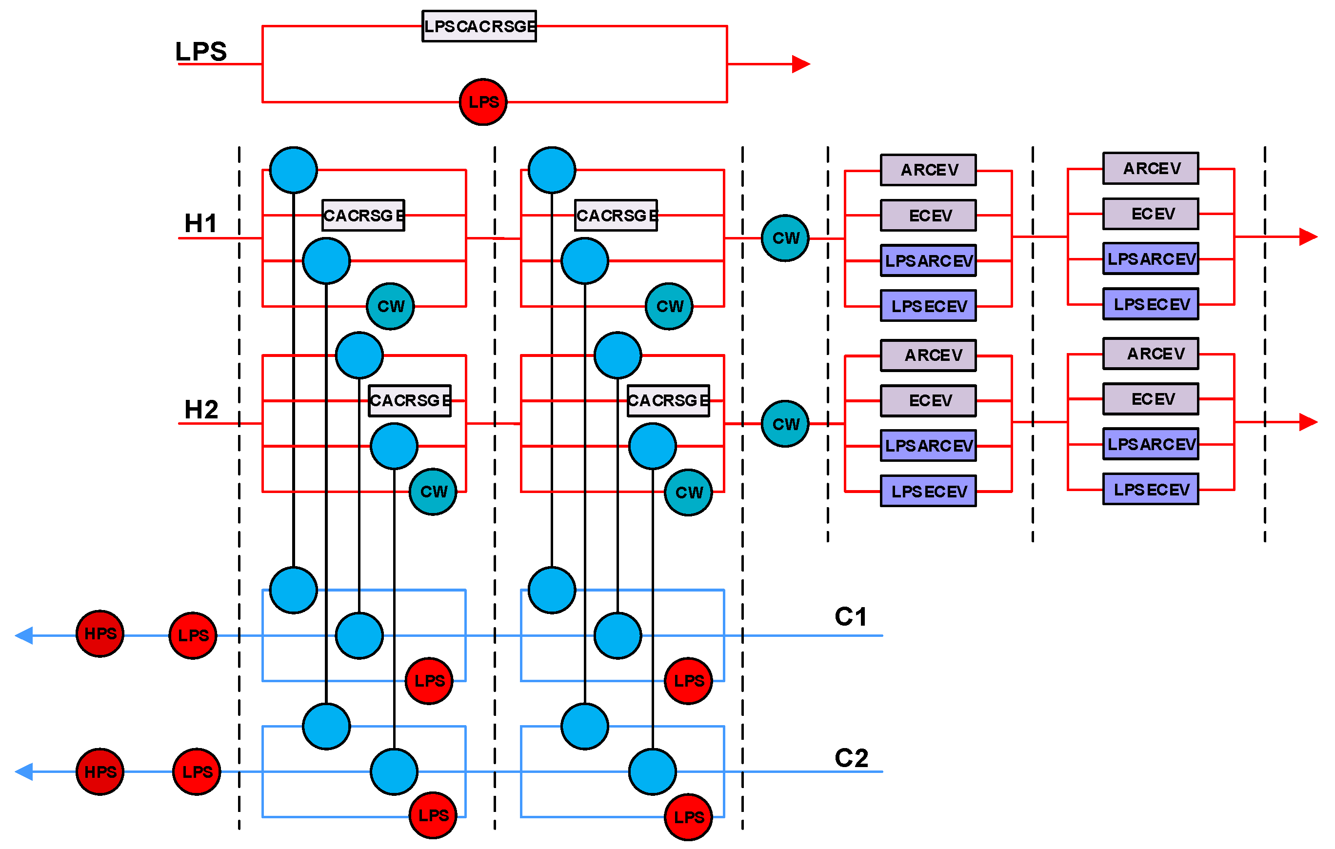
A stage-wise superstructure is proposed to present the configuration of HEN incorporated with the generation and evaporation processes of CACRS in
Figure 3. The cooperation of HEN and CACRS can be performed in two parts: (i) Hot process streams provide heat to drive the generators of absorption subsystem at the inner stage, (ii) low-temperature cooling energy produced in evaporators of absorption and compression subsystems are used to cool hot process streams to sub-ambient temperature or below 0 °C at the stream ends after the use of cooling water.
As indicated, the generation (CACRSGE) and evaporation processes of absorption (ARCEV) and compression (ECREV) subsystems are implemented cooperatively with the heat exchange of mentioned process streams. Also, low-pressure steam (LPS) can be used as heat source to motivate CACRS for producing cooling energy when hot process streams can’t provide enough heat. The corresponding generation and evaporation process are LPSCACRSGE, LPSARCEV, and LPSECREV. Each hot process stream can be cooled down by cold process stream, cooling water and/or the generation process (CACRSGE) and evaporation processes (ARCEV, ECREV, LPSARCEV, and LPSECREV) of CACRS, and each cold process stream can be heated by hot process stream, LPS and/or high-pressure steam (HPS). In addition, a two-stage structure of heat exchange between hot process stream and the evaporation processes of CACRS are performed at the stream end in order to include more matching possibilities.
3.3. Model Formulation
A MINLP model consisting of HEN and CACRS is formulated according to the superstructure proposed in this paper. The following sets are defined before presenting the model formulation: I, J, ST, ST’ represent the sets for hot process streams, cold process streams, stage numbers of heat exchange inside the superstructure, and stage numbers of heat exchange at end of the superstructure, S and L are the sets for temperature grades of evaporation processes for CACRS.
3.3.1. Model for Heat Exchanger Network Synthesis
● Total energy balances for process streams
Equations (3) and (4) represent the total energy balances for hot stream i and cold stream j. denotes the heat load provided by hot process stream i in generator of CACRS within stage k, denotes the cooling energy provided by the evaporation processes of CACRS within stage k’ at the stream end. and denote the use of cooling water inner stage and at the stream end of the superstructure. and denote the similar position of LPS as the placement of cooling water.
● Energy balance for each match inner stage of the superstructure
It should be note that , , all equal to , and equal to , on account that the inlet temperature of stage k is the outlet temperature after mixing in previous stage.
● Non-isothermal mixing for each inner stage
For process streams, the mass balances and energy balances for internal stages of the superstructure are shown as Equations (10)–(13). With these equations, the outlet temperature of stage k after mixing can be calculated.
● Energy balances for matches of evaporation processes at the stream ends
The heat removed by the evaporation processes of CACRS in any stage k’ which is at the ends of hot streams are given by Equations (14)–(17). and denote the heat removed by the evaporation process of absorption section motivated by hot process streams and LPS at stage k’ of hot process stream end, likewise, and have the similar meaning with and , but the evaporation process belongs to the compression section of CACRS.
● Energy balance of non-isothermal mixing for evaporation processes at the stream ends
● Energy balances for utilities at the stream ends
At the end of the superstructure, the heat removed by cooling water is determined by Equation (20), and the heat removed by the evaporation processes of CACRS are given by Equation (21). With Equations (22) and (23), the heating requirement of each cold process stream at the stream end are satisfied by LPS and HPS are determined.
● Feasibility constraints of temperature
Equation (24) denotes the temperature of hot process stream i will decrease after exchanging heat with M, M is the set including cold process stream, generator of CACRS, cooling water, and evaporators of CACRS. Similarly, Equation (25) denotes the temperature of cold process stream j will increase after exchanging heat with N which contains hot process stream, LPS and HPS. Equations (26) and (27) are used to ensure the monotonic decrease of temperature from the left side to the right side of the superstructure.
● Constraints on binary variables of CACRS
is the binary variable denoting the existence of generator of CACRS in stage k with the temperature of cooling energy produced in the evaporator belongs to grade s. and are binary variables that denote the cooling energy produced in grade s by absorption subsystem is used to cool hot process stream i at stage k’. and are binary variables which denote hot process streams are cooled down by the evaporation processes of CAVRS’s compression section in stage k’, of which s and l are the evaporation temperature grades of absorption section and compression section respectively.
The constraints on binary variable of CACRS are given by Equations (28)–(32). Equation (28) means that for the generation process of CACRS, there is at most one corresponding evaporation temperature of certain grade. Equations (29)–(32) indicate that for evaporation processes of CACRS, only one grade of evaporation temperature is considered so as to simplify the model and shorten computing time.
3.3.2. Model for CACRS
In the CACRS, condensation temperature and absorption temperature can be regarded as constants since the absorber and condenser are cooled down with cooling water which is used as cold utility in HEN with given inlet and outlet temperatures.
● The determination of matrix
In the case that condensation and absorption temperatures of absorption section are defined,
is only related to the inlet temperature of generator (heat source temperature)
and the evaporation temperature
for ARC,
can be determined by the condenser temperature (equal to
) and evaporation temperature
for ECR. Evaporation temperature of two subsystems are graded by discretizing into several values. Once the grades of these two evaporation temperatures are determined,
can be expressed as the function of
and the matrix of
can be established. The functional relation and values in matrix are obtained through process simulation and data fitting which are presented in
Section 3.1.
● Energy balance for CACRS
denotes the heat input from LPS to generator. Equations (34) and (35) give the energy balances of the CACRS, which means that the evaporator of absorption subsystem get heat from hot process stream and the condenser of compression subsystem.
3.3.3. Objective Function
The heat exchanging area can be calculated with Equation (36), herein,
and
represent the film heat transfer coefficients,
and
are the temperature differences before and after heat exchanging, the mean temperature difference is approximated according to Chen [
30]. Objective of the optimization is to minimize the TAC, considering both the expenditures of capital and operation for HEN and CACRS. The corresponding cost representations are given in Equations (38)–(40). HEN cost is the summation of capital cost for heat exchangers and operating cost for utility consumption. CACRS cost is deduced from the investment of absorption subsystem (containing generator, evaporator, condenser and absorber) and compression subsystem (cascaded evaporation-condenser, compressor and evaporator are included), as well as the cooling water consumption in the absorber and condenser which belong to absorption subsystem and the electricity consumption of compressor in compression subsystem.
4. Case Study
In this section, the proposed model is demonstrated through two case studies. To make comparison, a base case is set to cool down process streams by employing electrical compression refrigeration (R134a), which produces cooling energy by consuming electricity rather than process heat. Analogously, for the HEN integrated with ECR, each hot process stream is allowed to be cooled down by multiple parallel evaporation processes belonging to different grades after the using of cooling water. In the absorption subsystem of CACRS, LiBr/H2O is used as the working fluid. For single LiBr/H2O absorption refrigeration, the temperature of heat source is not allowed to be lower than 80 °C or higher than 180 °C. In this paper, the lower than 0.5 is not considered, so the designated range of heat source temperature is 105 °C to 175 °C. The minimum approach temperature for process stream matching and CACRS matching are stipulated to be , respectively. The inlet and outlet temperatures of cooling water are 30 °C and 40 °C, temperatures of LPS and HPS are 158 °C and 255 °C respectively. Similar to CACRS, the condenser of ECR is also cooled down by cooling water, and accordingly, the COP of ECR () can be determined by the selectable evaporation temperatures (denoted by s and l) which are identical to CACRS.
The data of the involved process streams for the two cases are shown in
Table 1 and
Table 2. In case 2, one more hot process stream is added into the HEN, which means more heat available, meanwhile more demand for cooling.
In order to optimize the operating condition of CACRS, six evaporation temperature alternatives for absorption subsystem and compression subsystem are given and graded respectively according to the requirement of target temperature. The grading about evaporation temperatures for absorption subsystem is shown in
Table 3. Similarly, the evaporation temperature for compression subsystem is also graded into six levels in the range of −25 °C to −5 °C, with
l1 to
l6 denoting −25 °C, −21 °C, −17 °C, −13 °C, −9 °C, and −5 °C respectively. Based on the simulation and data fitting procedures stated in
Section 3, the functional relation of
with
is obtained and presented as Equation (40), and the correlation coefficients are listed in
Table 3. Corresponding
in matrix
are given in Equation (41) according to the general presentation of Equation (33). When only ECR is used to satisfy the refrigeration demand, the
in matrix
is given in Equation (42), wherein, the
used to produce cooling energy below room temperature is given as Equation (43), and the
used to produce cooling energy lower than 0 °C is given as Equation (44).
The formulated MINLP mathematical models for mentioned HEN-CACRS and HEN-ECR designs are coded and solved in GAMS with PC specification: CPU 3.30 GHz, 8 GB RAM. For each model, BARON is used as solver. To be clear, note that the global optimum cannot be guaranteed for MINLP problems. Yet, good initial values and boundaries as well as circular iteration are employed to facilitate the search process and improve the quality of locally-optimal solutions.
In HEN-CACRS result, the evaporation temperature of grade ‘
s’ produced in ARC subsystem can cool hot process stream to below room temperature, and the evaporation temperature of grade ‘
l’, produced in ECR subsystem, can be used for cooling hot process stream to below 0 °C. For the integrated CACRS, (
s,
l) denotes that there is cooling energy produced at evaporation temperature of grade ‘
l’ by the compression section, whose temperature of cascaded evaporator-condenser belongs to grade ‘
s’, while for HEN-ECR result, just the evaporation temperature grade of ‘
s’ or ‘
l’ needs to be determined. Optimal structures of the integrated HENs with CACRS and ECR for two cases are presented in
Figure 4a,b and
Figure 5a,b, respectively.
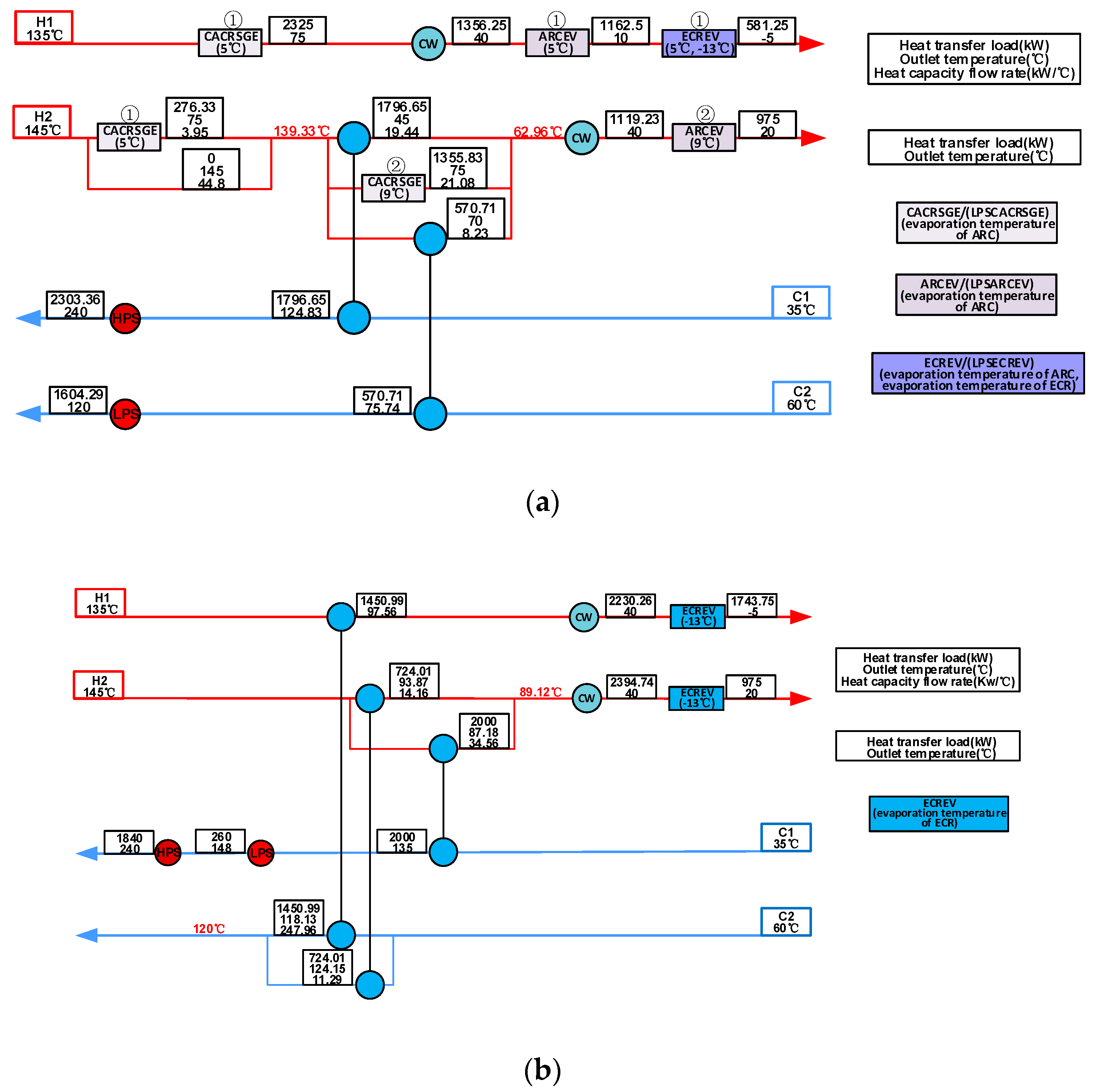
Figure 4a shows the optimal structure of HEN integrated with CACRS for case 1, as indicated in which one set of CACRS and one set of ARC are implemented to absorb heat from process stream for refrigeration purpose. The CACRSGE (5 °C) is motivated by H1 and H2, and the cooling energy, 5 °C (
s1) produced by the evaporation process of absorption section, and −13 °C (
l4) produced in evaporator of compression section are used to cool down H1 (ARCEV(5 °C), and ECREV (5 °C, −13 °C)) successively. In addition to exchanging heat with cold process stream and the generator of CACRS, H2 heats the generator of the ARC (CACRSGE (9 °C)), then to be refrigerated by the evaporation process of ARC (ARCEV(9 °C), (
s3)) after the use of cooling water. In HEN-ECR result, as shown in
Figure 4b, the mentioned refrigeration demands are all satisfied by ECRs. The evaporating temperature for refrigerating H1 and H2 are −13 °C (
l4).
For case 2, the optimal integrated structures of the two concerned design scenarios are shown in
Figure 5a,b.
For the scenario HEN integrated with CACRS, two ARC sets and two CACRS sets are involved to provide cooling energy to HEN. Since the heat of process streams is not sufficient, LPS is used to compensate the heat demand of CACRS. One ARC set is run by LPS (LPSCACRSGE (5 °C)), and the evaporator absorbs heat from H1 (LPSARCEV (5 °C), (s1)). The other ARC set gets heat from H3 in generator (CACRSGE (5 °C)) and the cooling energy produced in the evaporator is used to cool H2 and H3 (ARCEV (5 °C), (s1)). One CACRS is motivated by LPS (LPSCACRSGE (9 °C)), and the cooling energy produced in the evaporator of compression section is used to cool down H1 (LPSECREV (9 °C, −25 °C), (s3, l1)) at the stream end. The other CACRS gets heat from H2 (CACRSGE (7 °C)) and the cooling energy produced in the evaporator of absorption and compression subsystems is used for cooling H2 (ARCEV (7 °C), (s2)) and H3 (ECREV (7 °C, −25 °C), (s2, l1)) to their target temperatures separately.
5. Discussion
From obtained results of the two cases, it can be observed that, in HEN-CACRS and HEN-ECR scenarios, the process streams with cooling requirements are always cooled to the lowest temperature which can be achieved by cooling water first, and then are refrigerated by the evaporation processes of refrigeration system subsequently. The cause of this state is that cooling energy is produced at the cost of consuming much heat and electricity which will increase the operating cost. What is more, by comparing the optimal structure of HEN-CACRS with HEN-ECR, it can be observed that HEN-ECR prefers equal or higher evaporating temperature grades than that of CACRS at the last stage of evaporation processes. The reason for this tendency is that, higher evaporating temperature is beneficial for higher COP, which will decrease the consumption of expensive electricity.
Higher COP is pursued by both ECR and CACRS, which means consuming less electricity and heat. But when CACRS is integrated into HEN, high COP cannot be reached all the time due to the limit of cost target and characteristics of process streams (inlet temperature, outlet temperature, heat load and so on), there are trade-offs between the quantity and efficiency of heat recovery and between the cost of hot utility and electricity consumption.
For the absorption section, the lower the evaporation temperatures, the higher the hot source temperature (inlet temperature of generator) will be needed for higher . Such as the evaporation temperature used to cool H2 in case1 is 9 °C (s3), the corresponding heat source temperature is 139.33 °C, the evaporating temperature which is used to cool H1 is 5 °C (s1), and the matching heat temperature is 145 °C. But there is also 5 °C (s1) cooling energy produced, which is motivated the heat source of 135°C, for recovering much heat. Likewise, for the compression subsystem of CACRS, in case 2, there are two matches of evaporation temperatures for ARC section and ECR section, (7 °C, −25 °C) and (9 °C, −25 °C), obviously, the match of (7 °C, −25 °C) has higher , but the match of (9 °C, −25 °C) is motivated by LPS, higher evaporation temperature of ARC section will lead to higher and lower at the same time, so there is a trade-off between LPS and electricity consumption costs.
For the two cases, the optimal integrated HEN-ECR system are achieved at the TAC of 2,595,319
$·y
−1 and 4,780,274
$·y
−1, and the TAC of optimal integrated HEN-CACRS are 1,592,527
$·y
−1 and 2,970,188
$·y
−1, which are 38.6% and 37.9% lower than HEN-ECR respectively. The concrete analysis is as follows. The TAC consists of the capital cost of HEN, capital cost of CACRS and operating cost of HEN-CACRS. The operating cost of HEN-CACRS is composed of electricity cost, hot utility cost (LPS and HPS) and cold utility cost (cooling water). The cost of each part can be seen in
Figure 6.
Apparently, the capital cost of refrigeration forms a considerable part of TAC, and the cost of CACRS is close to that of ECR for the two cases studied. By comparing the cost difference of HEN-CACRS with HEN-ECR, it can be found that there is little difference in the capital cost of HEN, the hot and cold utilities costs of HEN-CACRS are higher than that of HEN-ECR, but the electricity cost of HEN-CACRS is much less than that of HEN-ECR. There are the detail explanations. In HEN-CACRS scenario, the integration of CACRS helps to promote energy efficiency of hot process streams, some waste heat is used to motivate the generator of CACRS, and the energy produced by the evaporators of CACRS can be used to partly meet the refrigeration demand, which lead to sharp decrease of electricity cost. Even though the utilization of waste heat can decrease the consumption of cooling water for cooling hot process streams, the cooling water cost of HEN-CACRS is still a little higher than that of HEN-ECR, because the cooling water consumed by the refrigeration system is also considered. In addition, the integration of CACRS into HEN may lessen the heat load matching with cold process stream or increase the consumption of LPS as heat source to motivate the refrigeration system, and result in the increase of hot utility cost. But with comprehensive consideration of all costs, it can be concluded that the TAC of HEN-CACRS is still lower than that of HEN-ECR.
6. Conclusions
This paper has presented a mathematical programming model to consider the integration of HEN with CACRS. The coupling relationship of CACRS and HEN are quantitatively described through process simulating and data fitting. Then a detailed mathematical description for CACRS and HEN is formulated. Considering the mutual effect of HEN and CACRS, the structure of the HEN and the performance of CACRS are optimized simultaneously within the design. Compared with the results of base case where only electrical compression refrigeration is used for refrigeration purpose, it can be found that the integrated HEN-CACRS system is capable to utilize energy reasonably and reduce the total annualized cost by 38.6% and 37.9% respectively since it could recover waste heat from hot process stream to produce the cooling energy required by the system. On base of this study, future work will be concentrated on the optimal design of the HEN integrated with CACRS and ORC, and more internal parameters will be considered.


