Article

Influence of Air Infiltration on Combustion Process Changes in a Rotary Tilting Furnace

1
Department of Thermal Technology and Gas Industry, Institute of Metallurgy, Faculty of Materials, Metallurgy and Recycling, Technical University of Kosice, Letna 9, 042 00 Kosice, Slovakia
2
Department of Chemical and Biochemical Engineering, Faculty of Chemical and Food Technology, Slovak University of Technology in Bratislava, Radlinskeho 9, 812 37 Bratislava, Slovakia
3
Department of Process Technique, Faculty of Manufacturing Technologies of the TU of Kosice with a Seat in Presov, Technical University of Kosice, Sturova 31, 080 01 Presov, Slovakia
*
Author to whom correspondence should be addressed.
Processes 2020, 8(10), 1292; https://doi.org/10.3390/pr8101292
Submission received: 24 September 2020 / Revised: 6 October 2020 / Accepted: 13 October 2020 / Published: 15 October 2020
(This article belongs to the Special Issue Progress in Energy Conversion Systems and Emission Control)

Abstract

:
Air infiltration into the combustion chambers of industrial furnaces is an unwanted phenomenon causing loss of thermal efficiency, fuel consumption increase, and the subsequent increase in operating costs. In this study, a novel design for a rotary tilting furnace door with improved construction features is proposed and tested experimentally in a laboratory-scale furnace, aimed at air infiltration rate reduction by decreasing the gap width between the static furnace door and the rotating body. Temperatures in the combustion chamber and oxygen content in the dry flue gas were measured to document changes in the combustion process with the varying gap width. Volumetric flow values of infiltrating air calculated based on measured data agree well with results of numerical simulations performed in ANSYS and with the reference calculation procedure used in relevant literature. An achievable air infiltration reduction of up to 50% translates into fuel savings of around 1.79 to 12% of total natural gas consumption of the laboratory-scale furnace. The average natural gas consumption increase of around 1.6% due to air infiltration into industrial-scale furnaces can thus likewise be halved, representing fuel savings of almost 0.3 m3 per ton of charge.

Graphical Abstract

1. Introduction

Reduction of the carbon footprint of industry is a primary objective of the European Union [1,2]. Energy efficiency, one of the pillars of the EU Energy Union strategy, has therefore been proposed as a solution, namely as a highly effective pathway to improve the economic competitiveness and sustainability of the European economy. Energy efficiency can help reduce the reliance on imports of fossil fuels, thereby bolstering energy security in the short- as well as long-term in a cost-effective way [3,4]. Currently, the metallurgical industry is one of the largest emitters of pollutants [5,6,7,8]. One of the possibilities of reducing the release of emissions is to increase the efficiency of combustion units, which leads to a decrease in fuel consumption [9]. Oxy-combustion technology or combustion at elevated oxygen concentrations in the oxidizing agent has been proposed as a novel and promising means to achieve this objective [10]. This type of combustion is referred to as oxygen-enhanced combustion (OEC) and has many benefits including increased processing rates [11], higher heat transfer efficiency [12,13], improved flame characteristics [14], reduced production of emissions [15], reduced equipment cost, and last but not least, improved product quality. It also represents an interesting route for decarbonization via carbon capture and storage [16,17]. OEC technology is most often applied in rotary tilting furnaces used in the processing of nonmetallic materials [18,19]. However, examples of how the iron and steelmaking industry can benefit from this technology as well have been recently summed up in [17]. Individual OEC technology applications in this industrial sector, related either to the proposed continuous scrap-melting rotary furnace, potentially replacing the electric arc furnace, or flameless oxy-fuel burners, are analyzed in detail in [20,21,22].
The rotary tilting furnace charge consists of a mixture of nonferrous wastes and dross, mostly based on aluminum and alumina [23]. The dross comes from primary aluminum production using bauxite. The processing of aluminum wastes using OEC technology has been published in more detail in studies [24,25].
Rotary tilting furnaces are characterized by having both the burner and the flue gas duct located in the door of the furnace, which remains static as the furnace body rotates [26]. To remove the flue gas, an exhaust fan is needed, which creates negative pressure in the combustion chamber. This causes the ambient air to infiltrate into the chamber, which significantly affects the combustion and heating of the charge in rotary tilting furnaces [27]. When OEC technology is used, the amount of penetrating air (79% vol. N2) increases the nitrogen concentration in the combustion chamber, thereby removing heat from the process and decreasing the combustion temperatures reached in the furnace [28,29]. Excessive air infiltration can, therefore, significantly lessen the advantages of using OEC technology and decrease the thermal efficiency of these furnaces.
On the other hand, oxygen content of the infiltrating air causes an increase in the oxygen concentration in the combustion chamber. Therefore, the charge material (aluminum) tends to react with the flue gas components [30]. The main reason for this is the high affinity of aluminum for oxygen. The surface of solid and liquid aluminum is always covered with an oxidation layer, which serves as protection against further oxidation. The chemical reaction in which aluminum reacts with oxygen to form alumina (Al2O3) is a self-propagating reaction [31]. Its initiation can be prevented by decreasing the oxygen content in the flue gas, which means regulating combustion with a low excess of the oxidizing agent and reducing air penetration into the furnace.
Prevention of air infiltration into the furnace in the furnace design stage is difficult due to the rotary movement of the kiln putting strain on the static door and leaving it with an improperly sealed opening [32]. A gap is gradually created through which air increasingly penetrates into the combustion chamber. The amount of air getting into the combustion chamber is influenced by the pressure conditions inside the chamber and by the width of the gap through which the air infiltrates. The amount of air penetrating into the combustion chamber can be estimated using the Bernoulli equation. In their studies, Varga [33] and Baukal [34] describe the method of calculating the amount of air getting into the combustion chamber and the associated energy required to heat the penetrating air up to the temperature of flue gas.
The physical measurement of the amount of infiltrating air and the definition of its impact on the combustion process under real conditions are difficult. Analyzing the amount of infiltrating air is possible only on the basis of flue gas composition and/or combustion control, by means of which the analysis of dry flue gas (O2, CO2, and CO) can determine the amount of excess combustion air.
At present, there is very little literature available that deals with the impact of air infiltration on heat transfer and charge heating in rotary tilting furnaces. The above-mentioned consequences of air penetration result in changes in the temperature field distribution inside the combustion chamber. Consequently, the charge heating process is significantly prolonged and its thermal efficiency is reduced. Attention should therefore be paid to this issue when evaluating the overall effect of air infiltration into furnace chambers. A solution to this issue lies in the modification of the furnace door design, which can reduce air infiltration through better sealing of the door opening, thus decreasing the gap through which air infiltrates into the furnace. In this way, a contribution can be made to achieving greater efficiency of oxygen use in furnaces, leading to an increased technological process efficiency and reduced greenhouse-gas emissions due to fuel savings. The authors of this article designed and created an experimental laboratory-scale model of a rotary tilting furnace with a novel design of the furnace door to investigate the impact of air infiltration on the combustion process and the resulting fuel consumption. Oxygen-enhanced combustion was applied with oxygen concentrations ranging from 21 to 35% vol. The computational fluid dynamics (CFD) model of the experimental device was designed and constructed for the better understanding of the impact of air infiltration on the combustion process. The obtained results confirm the ability of the new door design to reduce air penetration by up to 50% and to reduce the related fuel consumption by 1.79% to 12%, clearly demonstrating its superior performance compared to the traditional door design.
The rest of the paper is organized as follows: First, the modified furnace door design is introduced and its features are explained, along with a description of the laboratory-scale furnace used in the experiments and the instrumentation employed. The method for calculating the air infiltration rate is presented, followed by the results obtained and the related discussion. The CFD simulation and its results are presented in the next part, corroborating the experimental findings. Conclusions sum up the key findings.

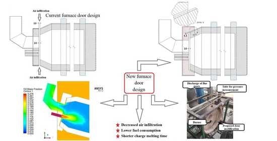
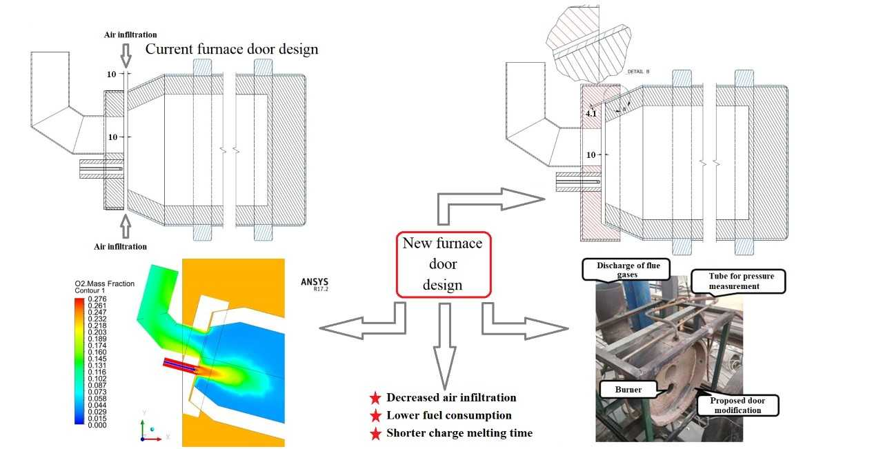
2. Experimental Device

2.1. Modification of the Door

The proposed furnace door modification aimed to reduce the gap between the furnace door and the furnace body itself, through which air penetrates into the furnace. The existence of the gap results from the industrial tilting furnace design, because the furnace door remains static while the furnace body rotates (see Figure 1). The size of the gap area through which air is sucked inside the furnace can be defined as the area of the cylinder mantle. The novel door design is based on elongating the perimeter surround of the door, which results in the partial covering of the rotating furnace body. This, in turn, leads to reduction in the gap area, as it results from Equations (1)–(3), and in the end, reduces air infiltration, as schematically shown in Figure 2. Additional air infiltration reduction results both from the increased relative roughness of the opposing walls and from the longer path the penetrating air must flow through to get inside the furnace. The key feature of the proposed novel door design is that the elongated part of the door surround is parallel and close to the wall of the rotating furnace body.
A schematic visualization of the gap width estimation is provided in Figure 2. The width of the gap between the door and the furnace body can be calculated using Equation (1). If the distance between the furnace door and body is reduced, the gap width can be calculated using Equations (1)–(3). For a better understanding, please see the auxiliary scheme provided in Figure 2. It follows from Equations (1) and (2) that the gap width reduction depends on the sine of angle α. In the ideal case, with no contact between the furnace door and the furnace body itself, the theoretical angle value is 0°. In this case, there is no gap and, consequently, zero air infiltration. While this situation is unreal, it still holds that as the angle α approaches zero, so does the gap width as well. The modified door design in the experiments yielded an angle α equal to 24.2°. Such experimental alignment produced a gap width of 4.1 mm, with the distance between the furnace door and the front of the furnace itself remaining at 10 mm. Please refer to Figure 1 as well. Figure 3 shows the modified furnace door design for better visualization.
x 0 = s i n α × h 1   ( m )
where x 0 —width of gap through which air infiltrates into furnace (m); h 1 —distance between extended door surround and rotary kiln body (m); α —angle between sloping body of rotary kiln and axis of furnace (°).
h 2 = h 1 Δ h   ( m )
x 1 = x 0 × h 2 h 1   ( m )
Figure 4 provides the values of the gap area through which air penetrates into the furnace with the traditional and with the new door design as a function of the furnace door distance from the furnace itself. As it can be seen from this figure, a reduction of around 50% in the gap area was achieved with the new door design. Theoretical calculations using the Bernoulli equation yielded the expected 50% reduction in air infiltration. The gap area in industrial-size rotary tilting furnaces is several times larger [13,35] compared with that in the laboratory furnace model, and the proposed door design modification can lead to a significant reduction in air penetration, improvement in combustion conditions, and subsequently increased thermal efficiency of the furnace.

2.2. Experimental Model

Experiments were carried out in a tilting rotary furnace (Figure 5) with an inside diameter of 305 mm and length of 607 mm. The angle of inclination of the experimental model during the measurement was 7%. In total, 16 thermocouples of type K (NICr-NiAl) PTTK-TKb-60-2-SP (Meratex s.r.o., Košice, Slovakia) were located in the furnace. The measurement uncertainty stated by the manufacturer is at the level of +/−2.5 °C at the temperature of 1200 °C. The objective of the thermocouples was to continuously monitor the changes in the temperature field in the combustion chamber, lining, stack, and charge. The experimental model was set-up statically due to the placement of thermocouples around the circumference of the casing, and it did not rotate during the measurements. The flue gas composition was analyzed using a TESTO-350XL flue gas analyzer (K-Test, s.r.o., Košice, Slovakia). The position of the flue gas analyzer and distribution of the thermocouples are shown in Figure 5.
Flow rates of all gaseous media were measured using Bronkhorst-designed MASS-VIEW series thermal mass flow meters/regulators. The devices operate on the principle of direct thermal mass flow measurement. The models utilized during these experiments were MV-308, MV-106, and MV-306 (AREKO s.r.o., Bratislava, Slovakia). Technical specifications of these models are listed in Table 1 and Table 2. Other relevant parameters related to the furnace operation were recorded by the furnace control system.
Effects of 21% to 35% oxygen concentration in the oxidizing agent on heat transfer in the furnace, flue gas temperature, and emissions produced were studied. At the same time, external effects such as air infiltration into the furnace were monitored. Table 3 shows the gas and combustion air and oxygen flow rates required to achieve the desired oxygen concentration in the oxidizing agent. Oxygen was added to the air input upstream of the burner using a diffuser to produce its uniform distribution. The addition of oxygen to the air stream has been described by Baukal and is intended for lower levels of oxygen enrichment of combustion air [6]. Natural gas was provided from the distribution network. The composition of this natural gas is presented in Table 4.

2.3. Calculation of Air Infiltration

The volumetric flow of air penetrating into the furnace can be calculated based on the material balance of the combustion process. The Testo 350XL flue gas analyzer provides concentrations of flue gas constituents (mainly oxygen) in the produced dry flue gas, which enables air excess coefficient calculation. Equations (4) and (5) present the calculation of the air excess coefficient and the volumetric flow of air infiltration.
m = 1 + V F G , D , m i n , y o 2 L m i n , y o 2 , × O 2 Y O 2 O 2   ( - )
V A I = m . L m i n × B V 1 × ( m 3 × h 1 )
where m is the air excess coefficient (-); V F G , D , m i n , y o 2 is the theoretical volume of flue gas (dry) if m = 1 (m3·m−3); L m i n , y o 2 is the theoretical volume of the oxidizing agent if m = 1 (m3·m−3); O 2 is the oxygen content in dry flue gases determined by means of flue gas analysis (% vol.); Y O 2 is the required oxygen concentration in oxygen-enriched combustion air for experimental measurement (%); V A I is the volumetric flow of air infiltration (m3·h−1); B is the consumption of fuel (m3·h−1); V 1 is the volumetric flow of oxidizing agent determined on the basis of Table 3 (m3·h−1).
The pressure difference between the ambient air and the inside of the furnace is related to the volumetric flow of air infiltration by Equation (6) if the frictional pressure losses are neglected. Their effect transposes into the measured oxygen content in the flue gases and, following that, into the calculated air infiltration.
Δ p = ( V A L / 3600 S x ) 2 × ρ A L 2   ( Pa )
where Δ p is the pressure difference (Pa); S x is the gap area (m2); ρ A L is the density of ambient air (kg·m−3).

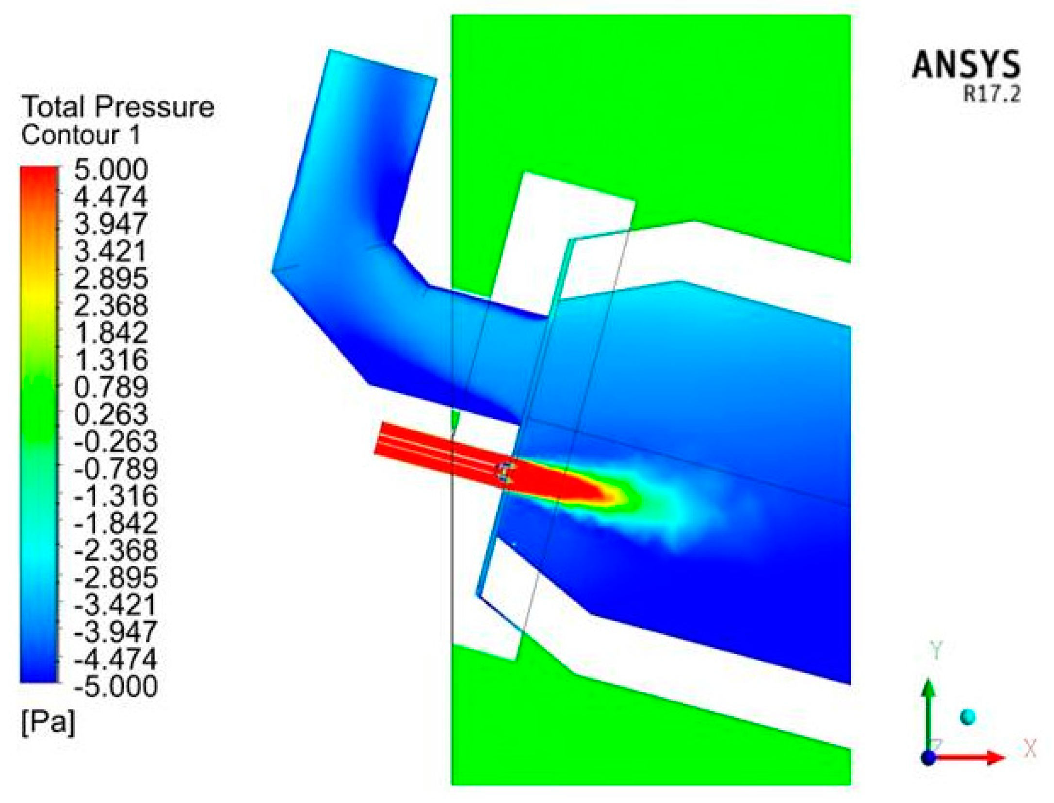
3. Results and Discussion

Figure 6 shows the measured oxygen concentration values (% vol.) in dry flue gas at various adjusted gap widths. Its linear increase with the increasing gap width can be observed, while the use of OEC had no visible effect on it. Based on Equations (4)–(6), it can be stated that underpressure in the furnace does not depend on the gap width; thus, the linear oxygen concentration increase results from the increasing gap area (see Figure 4). The oxygen concentration increase in the combustion air due to OEC technology use reduces the pressure difference between the furnace interior and the ambient air and reduces the air infiltration accordingly. The optimal oxygen concentration range in the dry flue gas with varying oxygen content in the enriched air (21 to 35% vol.) at the optimum air excess coefficient of m = 1.1 is depicted in Figure 6 (orange and red lines). Oxygen concentration values above the red line indicate air infiltration into the furnace. The difference between the red line and the measured oxygen concentration value at zero gap width (door touching the furnace body) results from the imperfect equipment geometry, worn-down refractory lining, or possibly from air infiltration through another, undetected, gap.
On the basis of flue gas analysis, the values of air infiltration volumetric flow were calculated depending on the gap width and oxygen concentration in the enriched air (21 to 35% vol.), standardized to fuel consumption of B = 1 (m3·h−1). The obtained trends are shown in Figure 7.
Results depicted in Figure 6 and Figure 7 demonstrate the possible situation occurring in real furnaces, where the expected gap width between the furnace door and the furnace body is much larger than that (10 mm) in the laboratory furnace employed during aluminum melting experiments.
Air infiltration increases combustion air excess and leads to increased thermal losses in flue gases exiting the furnace. At the same time, it leads to a decrease in the overall oxygen concentration in the oxidizing agent (sum of combustion air and air infiltration).
Figure 8 shows computational results of how the oxygen concentration in the oxidizing agent changes as air infiltrates into the combustion chamber. The optimum oxygen concentration in the oxidizing agent for melting aluminum in a rotary tilting furnace was found to be 35% based on experimental studies [19,24]. However, in the case of the estimated calculated air infiltration of up to 4.5 m3·h–1 (see Figure 7), this concentration value can be reduced by up to 14%.
The effects of the change in oxygen concentration in the oxidizing agent and that in excess combustion air can be transposed to the change in combustion temperatures through the statics of combustion. Figure 9 illustrates the impact of air infiltration on natural gas combustion temperature. Theoretical temperature, including the dissociation of CO2 and H2O components, is shown by the blue line. It is evident that the theoretical temperature decreases by more than 500 °C as the combustion conditions change due to air infiltration. Actual temperature in the furnace was calculated by applying the pyrometric efficiency factor of the experimental model (ηpyr = 0.45) determined by experimental measurements. Similarly, the actual temperature in the furnace decreases by more than 200 °C with the increasing air leakage. The charge material is thus heated by cooler flue gases, which increases the processing time of the charge, reduces the furnace productivity, and increases the fuel consumption.
Figure 10 provides measured flue gas temperature data from an experimental run during which the gap between the furnace door and body was decreased. Thermocouples T1 to T4 were placed in axial positions in the furnace; thus, they had the quickest response to changes in combustion conditions. Measured flue gas temperatures of around 700 °C increased to around 900 °C after the reduction in air infiltration intensity, which is in good agreement with the calculated temperatures shown in Figure 9. Axial distances of individual thermocouples from the burner are listed in Table 5.
The effect of decreasing air infiltration intensity during an experimental run can be further monitored by thermocouple T1 showing a decrease in flue gas temperature. The explanation is given above (p. 2): Penetrating air can be considered as secondary air, which accelerates creation of the combustible mixture by enhanced mixing of the fuel with the oxidizing agent. The flame front distance from the burner is reduced as a result. Decreasing air infiltration intensity slows down the creation of the combustible mixture and the flame front moves further away from the burner.
Measurement results in Figure 7 show that the operation of rotary tilting furnaces is inevitably coupled with significant air infiltration into the combustion chamber. The proposed new design of the furnace door leads to an around 50% decrease in the volumetric flow of air penetrating into the furnace, which represents a substantial change in the furnace operation. The resulting fuel saving rate can be partly calculated using Equations (7) and (8). Additional fuel savings, resulting from the shorter charge melting time, must be estimated experimentally case by case.
Q A I = L A I ˙ × C p A I × Δ T ( kJ · day 1 )
x = Q A I Q n N G × ( m 3 · day 1 )
where L A I ˙ is the flow rate of air infiltration per day (m3·day−1); c p A I is the specific heat capacity of infiltrating air (kJ m−3 K−1); Δ T is the difference in temperature (K); Q n N G is the calorific value of natural gas (kJ m−3); x is the natural gas equivalent (m3 day−1).
Data provided in Figure 7 (at oxygen concentration of 35%) at the ΔT value of 650 K, estimated by means of experimental measurements, permit the deduction that 0.6 to 3.68 m3/day of natural gas can be saved by the proposed novel furnace door design. This represents around 1.79 to 12% of the total daily natural gas consumption of the laboratory furnace. In the case of industrial-sized rotary tilting furnaces, the gap area is approximately 2.5 to 6 times larger compared to the laboratory-scale furnace used in this study [38] depending on the furnace throughput. The average natural gas consumption in this type of furnace is 35 m3 per ton of charge. Applying the results obtained from the laboratory-scale furnace model, the air infiltration rate into a typical industrial furnace ranges between 17 and 120·m3·h−1. The calculated air infiltration rate into a real furnace [6] was 23 m3/h, which led to an additional natural gas consumption of 10 m3·day−1. This represents approximately 1.6% of the average natural gas consumption in that furnace, or around 0.56 m3 of natural gas per ton of charge. Halving this amount by means of the proposed novel furnace door design produces a saving of almost 0.3 m3 per ton of charge on average.
In the case of furnaces using pure oxygen for natural gas combustion, the oxygen concentration in the combustible mixture is reduced to around 80% of its original value due to air infiltration. The theoretical combustion temperature, taking CO2 and H2O dissociation into account, then drops by around 150 °C.

4. Mathematical Modeling

The effects of air infiltration into a furnace can be illustrated using mathematical modeling with CFD simulation. Nieckele et al. [38] described the numerical modeling of an industrial aluminum melting furnace. Zhou et al. [39] performed the modeling of aluminum scrap processing in a rotary furnace. Khoei et al. [40] modeled the operation of a rotary furnace in aluminum recycling processes. Rimar et al. [41] developed a mathematical model of a heating furnace implemented with volumetric fuel combustion. The mathematical model of the furnace shown in Figure 3 and Figure 5 was developed in ANSYS. Boundary conditions were defined based on the heat balance result and in accordance with Table 3. Gas and oxidizing agent were defined in terms of the mass flow rate. The boundary condition of the chimney was specified as an opening with pressure condition “−5 Pa,” which was defined as negative pressure created by the exhaust fan. The furnace border (surround) was defined by the boundary condition “Opening,” where the specified pressure was equal to the atmospheric one, and the air composition was 21% of O2 and 79% of N2. The mesh of the mathematical model was created from tetrahedral, hexahedral, and prism cells. Meshing in the vicinity of the furnace walls was supported by the inflation function with the inflation option “Smooth transition” and a maximum of five layers, and growth rate of 1.2. Figure 11 provides a visualization of the mesh of the mathematical model. The total number of cells was 2,086,018. In order to simplify the mathematical model, the furnace was modeled in the empty state, i.e., with no charge inside.
Results of the mathematical modeling presented in Figure 12 confirm that when melting aluminum in the physical model, air infiltrates into the furnace combustion chamber. Analysis of the results shows that the actual measurement of emissions with the probe in the stack of the physical model is also influenced by air infiltration. There is a layer of unburned oxygen close to the chimney walls, which is diluted with flue gases created during natural gas combustion. Thus, the optimum location of the flue gas analysis probe is along the stack axis near the combustion chamber, i.e., exactly where it was placed during our experiments.
Due to the small pressure difference between the ambient air and the furnace interior, the pressure contours range had to be rescaled to ±5 Pa. Figure 13 clearly shows the overpressure in the burner, which quickly diminishes due to the flue gas outflow into the stack. Areas with lowest pressure are located close to the burner and further toward the stack as a result of the flue gas fan operation drawing off produced flue gas.
From the results of the mathematical model, the extent to which air infiltration affects the natural gas combustion process can also be determined. Figure 14 shows the distribution of infiltrating air in the combustion chamber by means of streamlines. The exhaust fan creates negative pressure in the chimney, and therefore, a large portion of the penetrating air is drawn directly into the flue gas, creating an air layer on the chimney walls. In proximity of the burner, the penetrating air is propelled into the combustion chamber by the flue gas flow. Thus, an excess of oxygen is generated in the combustion chamber, creating an oxidizing atmosphere above the charge.
Data presented in Figure 15 validate the model and calculation results of air infiltration volumetric flow through their comparison with values obtained using the method proposed by Baukal [35]. Both modeling approaches yielded similar results to those from the calculation based on experimental measurements. Thus, the method used for mathematical model creation in ANSYS can be considered as correct, and the results obtained are relevant and can be used for fuel consumption reduction estimation resulting from the proposed furnace door design change.

5. Conclusions

The authors have proposed and experimentally tested an improved design for a rotary tilting furnace door. Its ability to reduce air infiltration into the furnace was confirmed both experimentally and by numerical simulations in ANSYS. Temperatures in the combustion chamber and oxygen content in dry flue gas were measured in order to document the changes in the combustion process with varying gap width around the furnace door. The calculated air infiltration volumetric flow values based on the measured data agree well with the results of numerical simulations performed in ANSYS, as well as with the reference calculation procedure used in relevant literature. The achieved air infiltration reduction of up to 50% translates into fuel savings amounting to around 1.8 to 12% of the total natural gas consumption in the laboratory-scale furnace. Applying the results obtained here to industrial-scale furnaces permits us to state that typical air infiltration rates vary in the range from 17 to 120 m3·day−1 and cause a fuel consumption increase of 1.6% on average, which represents around 0.56 m3 of natural gas per ton of charged material. Based on these experimental results, it can be concluded that this value can be halved by means of the novel furnace door design.
Based on the results of both experimental measurement and mathematical modeling of the rotary tilting furnace device, it can be concluded that the infiltration of air into the combustion chamber causes serious impact on the combustion process and reduces the energy efficiency of rotary furnaces. From the environmental point of view, the main disadvantage is the associated increase in greenhouse gas emissions into the atmosphere and the increase in fuel consumption. The results obtained reflect the trends in EU energy policy aimed strictly at industrial carbon footprint reduction, and research in this area is, therefore, very useful and highly topical.

Author Contributions

Conceptualization, A.V. and J.K.; methodology, R.D. and J.K.; validation, M.P. and L.L.; investigation, R.A. and R.D.; resources, G.J.; data curation, L.L. and J.K.; writing—original draft preparation, R.D., M.V. and G.J.; writing—review and editing, M.V., M.P. and R.A.; visualization, R.D. and M.V.; funding acquisition, A.V. and G.J. All authors have read and agreed to the published version of the manuscript.

Funding

This research was funded by the VEGA 1/0691/18 project and by the Slovak Research and Development Agency under contract no. APVV-15-0148 and the obtained results are part of the solution of these grant projects.

Conflicts of Interest

The authors declare no conflict of interest. The funders had no role in the design of the study; in the collection, analyses or interpretation of data; in the writing of the manuscript, nor in the decision to publish the results.

References

  1. Nakadate, M. OECD: Organization for Economic Co-operation and Development. Jpn. J. Water Pollut. Res. 1991, 14, 437–443. [Google Scholar] [CrossRef] [Green Version]
  2. Gerres, T.; Ávila, J.P.C.; Llamas, P.L.; Román, T.G.S. A review of cross-sector decarbonisation potentials in the European energy intensive industry. J. Clean. Prod. 2019, 210, 585–601. [Google Scholar] [CrossRef]
  3. Malinauskaite, J.; Jouhara, H.; Ahmad, L.; Milani, M.; Montorsi, L.; Venturelli, M. Energy efficiency in industry: EU and national policies in Italy and the UK. Energy 2019, 172, 255–269. [Google Scholar] [CrossRef]
  4. Rissman, J.; Bataille, C.; Masanet, E.; Aden, N.; Morrow, W.R.; Zhou, N.; Elliott, N.; Dell, R.; Heeren, N.; Huckestein, B.; et al. Technologies and policies to decarbonize global industry: Review and assessment of mitigation drivers through 2070. Appl. Energy 2020, 266. [Google Scholar] [CrossRef]
  5. Boryca, J.; Kolmasiak, C.; Wylecial, T.; Urbaniak, D. Effect of furnace efficiency on scale adhesion in steel charge heating process. Metalurgija 2020, 59, 191–194. [Google Scholar]
  6. Nidheesh, P.; Kumar, M.S. An overview of environmental sustainability in cement and steel production. J. Clean. Prod. 2019, 231, 856–871. [Google Scholar] [CrossRef]
  7. De Ras, K.; Van De Vijver, R.; Galvita, V.V.; Marin, G.B.; Van Geem, K.M. Carbon capture and utilization in the steel industry: Challenges and opportunities for chemical engineering. Curr. Opin. Chem. Eng. 2019, 26, 81–87. [Google Scholar] [CrossRef]
  8. Sun, W.; Wang, Q.; Zhou, Y.; Wu, J. Material and energy flows of the iron and steel industry: Status quo, challenges and perspectives. Appl. Energy 2020, 268, 114946. [Google Scholar] [CrossRef]
  9. Filipponi, M.; Rossi, F.; Presciutti, A.; De Ciantis, S.; Castellani, B.; Carpinelli, A. Thermal Analysis of an Industrial Furnace. Energies 2016, 9, 833. [Google Scholar] [CrossRef] [Green Version]
  10. Naranjo, R.D.; Kwon, J.; Majumdar, R.; Choate, W.T. Advanced Melting Technologies: Energy Saving Concepts and Opportunities for the Metal Casting Industry, 2005. U.S. Department of Energy. pp. 19–20. Available online: https://www1.eere.energy.gov/manufacturing/resources/metalcasting/pdfs/advancedmeltingtechnologies.pdf (accessed on 25 August 2020).
  11. Baukal, C. Oxygen-Enhanced Combustion; CRC Press: Boca Raton, FL, USA, 2013. [Google Scholar]
  12. Wu, K.-K.; Chang, Y.-C.; Chen, C.-H.; Chen, Y.-D. High-efficiency combustion of natural gas with 21–30% oxygen-enriched air. Fuel 2010, 89, 2455–2462. [Google Scholar] [CrossRef]
  13. Jablonský, G.; Pástor, M.; Dzurňák, R. Enriching the Combustible Mixture with Oxygen in Practice (in Slovak). TU of Košice, Košice, 2015. Available online: https://uloz.to/file/ZPAXaG9LqLd5/monografia-jablonsky-spolu-pdf (accessed on 25 August 2020).
  14. Baukal, C.E., Jr. Industrial burners handbook, 1st ed.; CRC Press: Boca Raton, FL, USA, 2004; pp. 650–726. [Google Scholar]
  15. Poskart, A.; Radomiak, H.; Niegodajew, P.; Zajemska, M.; Musiał, D. The Analysis of Nitrogen Oxides Formation During Oxygen—Enriched Combustion of Natural Gas. Arch. Met. Mater. 2016, 61, 1925–1930. [Google Scholar] [CrossRef]
  16. Leeson, D.; Mac Dowell, N.; Shah, N.; Petit, C.; Fennell, P.S. A Techno-economic analysis and systematic review of carbon capture and storage (CCS) applied to the iron and steel, cement, oil refining and pulp and paper industries, as well as other high purity sources. Int. J. Greenh. Gas Control. 2017, 61, 71–84. [Google Scholar] [CrossRef]
  17. Wang, R.; Jiang, L.; Wang, Y.; Roskilly, A. Energy saving technologies and mass-thermal network optimization for decarbonized iron and steel industry: A review. J. Clean. Prod. 2020, 274. [Google Scholar] [CrossRef]
  18. D’Agostini, M. High-Efficiency, High-Capacity, Low-NOx Aluminum Melting Using Oxygen-Enhanced Combustion; DOE/ID/13514; U.S. Department of Energy: Washington, DC, USA, 2000; pp. 10–35. [CrossRef] [Green Version]
  19. Dzurnak, R.; Varga, A.; Kizek, J.; Jablonský, G.; Lukáč, L. Influence of Burner Nozzle Parameters Analysis on the Aluminium Melting Process. Appl. Sci. 2019, 9, 1614. [Google Scholar] [CrossRef] [Green Version]
  20. Zhang, Y.; Barr, P.V.; Meadowcroft, T.R. Continuous scrap melting in a short rotary furnace. Miner. Eng. 2008, 21, 178–189. [Google Scholar] [CrossRef]
  21. Ghadamgahi, M.; Ölund, P.; Ekman, T.; Andersson, N.; Jönsson, P. Numerical and experimental study on flameless oxy-fuel combustion in a pilot-scale and a real-size industrial furnace. Appl. Therm. Eng. 2018, 141, 788–797. [Google Scholar] [CrossRef]
  22. Carabalí, D.M.; Forero, C.R.; Cadavid, Y. Energy diagnosis and structuring an energy saving proposal for the metal casting industry: An experience in Colombia. Appl. Therm. Eng. 2018, 137, 767–773. [Google Scholar] [CrossRef]
  23. Blašková, K.; Trpčevská, J.; Kuchárová, M. Characterization of Zn-Mg-Al Based Drosses from the Continuous Galvanizing. Manuf. Technol. 2016, 16, 879–883. [Google Scholar] [CrossRef]
  24. Jepson, S.; Kampen, P.V. Oxygen-enhanced combustion provides advantages in Al-melting furnaces. Ind. Heat. 2005, 72, 29–35. [Google Scholar]
  25. Gripenberg, H.; Johansson, A.; Eichler, R.; Rangmark, L. Optimised oxyfuel melting process at sapa heat transfer ab. In Proceedings of the Light Metals 2007 at the TMS 2007 Annual Meeting & Exhibition, Orlando, FL, USA, 25 February–1 March 2007; Sorlie, M., Minerals, Metals and Materials Society, Eds.; TMS: Warrendale, PA, USA, 2007; pp. 597–601. [Google Scholar]
  26. Gripenberg, H.; Falk, O.; Olausson, R.; Niedermair, F. Controlled melting of secondary aluminum in rotary furnaces. In Proceedings of the Light Metals 2003 at the 132nd TMS Annual Meeting, San Diego, CA, USA, 2–6 March 2003; Crepeau, P.N., Minerals, Metals and Materials Society, Eds.; TMS: Warrendale, PA, USA, 2003; pp. 1083–1090. [Google Scholar]
  27. Furu, J.; Buchholz, A.; Bergstrøm, T.H.; Marthinsen, K. Heating and melting of single Al ingots in an aluminum melting furnace. In Proceedings of the Light Metals 2010 at the TMS 2010 Annual Meeting & Exhibition, Seattle, WA, USA, 14–18 February 2010; Johnson, J.A., Ed.; TMS-AIME: Warrendale, PA, USA, 2010; pp. 679–684. [Google Scholar]
  28. Rimar, M.; Kulikov, A. NOx formation in combustion of gaseous fuel in ejection burner. In The Application of Experimental and Numerical Methods in Fluid Mechanics and Energy, Proceedings of the XX. Anniversary of International Scientific Conference, Terchova, Slovakia, 27–29 April 2016; AIP Publishing: College Park, MD, USA, 2016; Volume 1745, p. 20051. [Google Scholar]
  29. Kulikov, A.; Fedák, M.; Abraham, M.; Váhovský, J. Study of the gaseous fuel combustion respect to the O2 concentration and NOx formation. Adv. Therm. Process. Energy Transform. 2018, 1, 23–26. [Google Scholar]
  30. Capuzzi, S.; Timelli, G. Preparation and Melting of Scrap in Aluminum Recycling: A Review. Metals 2018, 8, 249. [Google Scholar] [CrossRef] [Green Version]
  31. Osoba, L.O.; Owolabi, O.B.; Talabi, S.I.; Adeosun, S.O. Review on oxide formation and aluminum recovery mechanism during secondary smelting. J. Cast. Mater. Eng. 2018, 2, 45–51. [Google Scholar] [CrossRef]
  32. Baukal, C. The John Zink Hamworthy Combustion Handbook; CRC Press: Boca Raton, FL, USA, 2012. [Google Scholar] [CrossRef]
  33. Varga, A.; Jablonský, G.; Lukáč, L.; Kizek, J. Thermal Technology for Metallurgists; TU of Košice: Košice, Slovakia, 2013. (in Slovak). Available online: https://opac.lib.tuke.sk/tukeopac/openURL?fn=*recview&uid=373383&pageId=main&full=0 (accessed on 25 August 2020).
  34. Baukal, C.E.; Bussman, W.R. Air infiltration effects on industrial combustion efficiency. In Fuel Efficiency, 2nd ed.; Bernard, J.K., Ed.; Nova Science Publishers: Hauppauge, NY, USA, 2011; pp. 101–103. [Google Scholar]
  35. Melting Solutions: Tilting Rotary Furnace World Class Melting Technology. Available online: http://www.meltingsolutions.co.uk/wp-content/uploads/2016/07/TRF-Brochure-new-low.pdf (accessed on 25 August 2020).
  36. Mass View: The Intelligent Alternative for VA Meters: Mass Flow for Gases with Flow Display. Available online: https://www.bronkhorst.com/getmedia/88dd3dac-0ddd-4dec-887f-8c3d34b28028/MASS-VIEW_EN.pdf (accessed on 25 August 2020).
  37. SPP-Distribucia. Available online: https://www.spp-distribucia.sk/dodavatelia/informacie/zlozenie-zemneho-plynu-a-emisny-faktor/ (accessed on 25 August 2020).
  38. Nieckele, A.O.; Naccache, M.F.; Gomes, M.S.P. Numerical Modeling of an Industrial Aluminum Melting Furnace. J. Energy Resour. Technol. 2004, 126, 72–81. [Google Scholar] [CrossRef]
  39. Zhou, B.; Yang, Y.; Reuter, M.A.; Boin, U. Modelling of aluminium scrap melting in a rotary furnace. Miner. Eng. 2006, 19, 299–308. [Google Scholar] [CrossRef]
  40. Khoei, A.R.; Masters, I.; Gethin, D. Numerical modelling of the rotary furnace in aluminium recycling processes. J. Mater. Process. Technol. 2003, 139, 567–572. [Google Scholar] [CrossRef]
  41. Rimar, M.; Kulikov, A.; Fedak, M.; Yeromin, O.O.; Sukhyy, K.; Gupalo, O.; Belyanovskaya, E.; Berta, R.; Smajda, M.; Ratnayake, M. Mathematical Model of a Heating Furnace Implemented with Volumetric Fuel Combustion. Processes 2020, 8, 469. [Google Scholar] [CrossRef]
Figure 1. (a) Traditional design of door, (b) proposed design of door.
Processes 08 01292 g001
Figure 2. Visualization of gap width estimation.
Processes 08 01292 g002
Figure 3. Door of the experimental furnace model.
Processes 08 01292 g003
Figure 4. Gap area dependence on gap width in the traditional and the proposed new door design.
Processes 08 01292 g004
Figure 5. Experimental model of tilting rotary kiln.
Processes 08 01292 g005
Figure 6. Oxygen concentration in dry flue gas in % vol. measured by flue gas analyzer at varying gap width values. Orange and red lines indicate the range of values corresponding to an optimal combustion air excess of m = 1.1 at 21 to 35% oxygen content in combustion air.
Processes 08 01292 g006
Figure 7. Dependence of calculated specific air infiltration volumetric flow (m3 per m−3 of combusted natural gas) on gap width.
Processes 08 01292 g007
Figure 8. Dependence of oxygen concentration and combustion air excess on the amount of infiltrating air (mathematical modeling).
Processes 08 01292 g008
Figure 9. Dependence of temperature change with air infiltration.
Processes 08 01292 g009
Figure 10. Changes in flue gas temperatures in combustion chamber as a result of decreasing air infiltration intensity (experimental measurements).
Processes 08 01292 g010
Figure 11. Mesh of the mathematical model.
Processes 08 01292 g011
Figure 12. Model results: Distribution of oxygen mass fraction contours.
Processes 08 01292 g012
Figure 13. Model results: Pressure contours distribution.
Processes 08 01292 g013
Figure 14. Model results: Infiltrating air flow contours in the combustion chamber.
Processes 08 01292 g014
Figure 15. Comparison of air infiltration volumetric flow: Calculated using experimental data (orange); obtained from modeling in ANSYS (yellow); and calculated using the approach proposed by Baukal [35] (green).
Processes 08 01292 g015
Table 1. Technical specification of Bronkhorst flowmeters MASS-VIEW MV-106, MV-306, and MV-308 [36]. FS = full scale; RD = reading.
MV-106, MV-306MV-308
Accuracy±2% RD for >50% of max. capacity
±(2% RD + 0.5% FS) on lower flows
Repeatability<0.2% FS typical<0.6% FS typical
Operating pressure0–10 bar
Operating temperature0–50 °C
Response time2 s
Table 2. Flow rate specification of Bronkhorst flowmeters MASS-VIEW MV-106, MV-306, and MV-308 [36].
Model Air, O2 (L/min)CH4 (L/min)
MV-106,
MV-306
range 12–2001–100
range 21–1005–50
range 30.5–500.2–20
range 40.4–200.2–10
MV-308range 15–5002.5–250
range 22–2001.25–125
range 31–1000.625–62.5
range 41–500.5–25
Table 3. Volumetric flows of inlet media depending on oxygen concentration in the oxidizing agent.
Concentration of Oxygen(%)2122.52527.53032.535
Air Flow(m3·h−1)14.0712.8811.229.868.727.776.94
Oxygen Flow(m3·h−1)00.250.60.881.121.321.49
Fuel Consumption(m3·h−1)1.31.31.31.31.31.31.3
Air Excess coefficient(-)1.11.11.11.11.11.11.1
Table 4. Natural gas composition in % vol. (adapted from [37]).
CH4C2H6C3H8C4H10C5H12C6H14CO2N2
%%%%%%%%
95.1712.71310.87290.27720.04860.02070.22660.6697
Table 5. Axial distances of individual thermocouples from the burner.
ThermocoupleT1T2T3T4
Distance (m)0.050.20.350.5
Publisher’s Note: MDPI stays neutral with regard to jurisdictional claims in published maps and institutional affiliations.

