Article

Influence of Eccentricity on Hydrodynamic Characteristics of Nuclear Reactor Coolant Pump under Different Cavitation Conditions

National Research Center of Pumps, Jiangsu University, Zhenjiang 212013, China
*
Author to whom correspondence should be addressed.
Processes 2020, 8(1), 98; https://doi.org/10.3390/pr8010098
Submission received: 12 November 2019 / Revised: 3 January 2020 / Accepted: 7 January 2020 / Published: 10 January 2020
(This article belongs to the Section Advanced Digital and Other Processes)

Abstract

:
In order to study the influence of eccentricity on hydrodynamic characteristics of nuclear reactor coolant pump under different cavitation conditions, five different schemes were obtained by analyzing and optimizing the existing structural schemes. Based on the RNG k-ε model (Renormalization Group with k-epsilon turbulence models) and two-fluid two-phase flow model, the unsteady numerical analysis and test verification of different designed schemes are carried out by using the flow field software ANSYS CFX. The results of research show that different eccentricities will affect the nuclear reactor coolant pump’s head under different cavitation conditions, and the corresponding head in the scheme with the eccentricity of 5mm under the fracture cavitation condition is lower than that of the other schemes. When the impeller rotates at a certain angle from the initial position under critical and severe cavitation conditions, the radial force acting on the rotor system will fluctuate greatly. Under the condition of fracture cavitation, the radial force changed periodically and the resultant force value is small. Compared to the original scheme, the peak value of radial force is 6° clockwise after eccentricity of the impeller appeared. With the aggravation of cavitation condition, the axial force value of impeller decreases, but the corresponding amplitude of the impeller increases. Under critical and severe cavitation conditions, the maximum axial force amplitude of the nuclear reactor coolant pump appears in the two times blade frequency, and in the broken cavitation condition, the maximum axial force amplitude appears at the shaft frequency. When the eccentricity is 20 mm, the axial force fluctuates most under critical and severe cavitation conditions, and when the eccentricity is 10 mm, the corresponding axial force is smaller than that of the original scheme. When the eccentricity is 5 mm, the axial force on the impeller is the smallest, but the amplitude is the largest under the condition of fracture cavitation.

1. Introduction

Despite the disastrous nuclear accident that occurred in Fukushima in 2011, nuclear energy, as a vital part of world energy, will not be affected in the future development [1]. However, the shadow of nuclear accidents cannot be ignored. The risk research of nuclear power plants has become one of the most important topics in this field [2]. As one of the core equipment of nuclear power plant, the nuclear reactor coolant pump and its ability to operate safely and steadily for a long time plays a vital role in the safe and stable operation of the whole nuclear power plant [3].
Small break loss of coolant accident (SBLOCA), a commonly analyzed accident condition, will lead to a sharp decrease in environmental pressure, resulting in cavitation in the impeller of the nuclear reactor coolant pump [4,5]. Cavitation will cause the energy exchange of liquid to be interfered and destroyed, causing a series of problems such as a change in pump operation characteristics, vibration, and noise [6]. Finally, it will affect the capacity of the pump to convey coolant [7].
Scholars have studied the flow characteristics and radial forces of pumps under cavitation conditions. Lu Pengbo et al. used the speed coefficient method to design the impeller and guide blade of the nuclear reactor coolant pump and obtained the law of the influence of the nuclear reactor coolant pump structure on cavitation [8]. Zhang Yu et al. used numerical simulation methods to obtain the critical pressure and critical temperature of cavitation of the nuclear reactor coolant pump by steady state calculation [9]. Wang Yiming et al. carried out numerical calculations of cavitation in a mixed flow nuclear reactor coolant pump, and the cavitation performance of the nuclear reactor coolant pump was improved through numerical prediction [10]. Wang Xiuli et al. used ANSYS CFX software to conduct simulate analysis on the hydrodynamic characteristics of the nuclear reactor coolant pump in cavitation transition process and got the fluctuation rule of pressure and head in the pump [11]. Shi Weidong et al. carried out unsteady numerical calculations on the non-overload sewage pump, and the effect of centrifugal pump clearance on pressure fluctuation and radial force was studied [12]. Wang Peng et al. studied the influence of eccentricity on the internal flow of the nuclear reactor coolant pump and obtained the influence rule of eccentricity on radial force under single phase working conditions [13]. Meng L et al. studied the effect of interaction between impeller and volute on the cavitation behavior of centrifugal pumps [14]. Ran Tao et al. studied the cavitation performance of pump turbines under pump mode [15]. Qiang Fu et al. studied the flow characteristics of the inner impeller channel of a nuclear centrifugal pump under the condition of steady and transient cavitation condition [16]. However, the cavitation evolution of the nuclear reactor coolant pump impeller in different cavitation and the radial force and axial force variation on the impeller are seldom studied, especially the effect of the eccentric distance of the impeller on the nuclear reactor coolant pump in different cavitation states [17]. Lu Y. et al. studied the third and fourth generation reactor coolant pumps, main including gas-liquid two-phase flow and the transient characteristics of pump under extreme operating conditions, and finding in different gas fraction conditions, the homogeneous distribution of gas phase component in the fluid area was mainly related to the operating condition of pump, and when the volume flow rate deviates from the designed operating point, the fluid medium’s gas phase and liquid phase will separate to some extent [18,19,20].
In order to further study the effect of eccentricity on the cavitation of the nuclear reactor coolant pump and the radial force and axial force of the impeller under different cavitation conditions, this paper will adopt the eccentricity principle described in the literature and use the flow field analysis software ANSYS CFX to simulate the internal flow field of the nuclear reactor coolant pump in three different cavitation states. The cavitation characteristic, radial force and axial force of different eccentric nuclear reactor coolant pumps are analyzed. The obtained results can provide reference for the design of new nuclear main pumps.

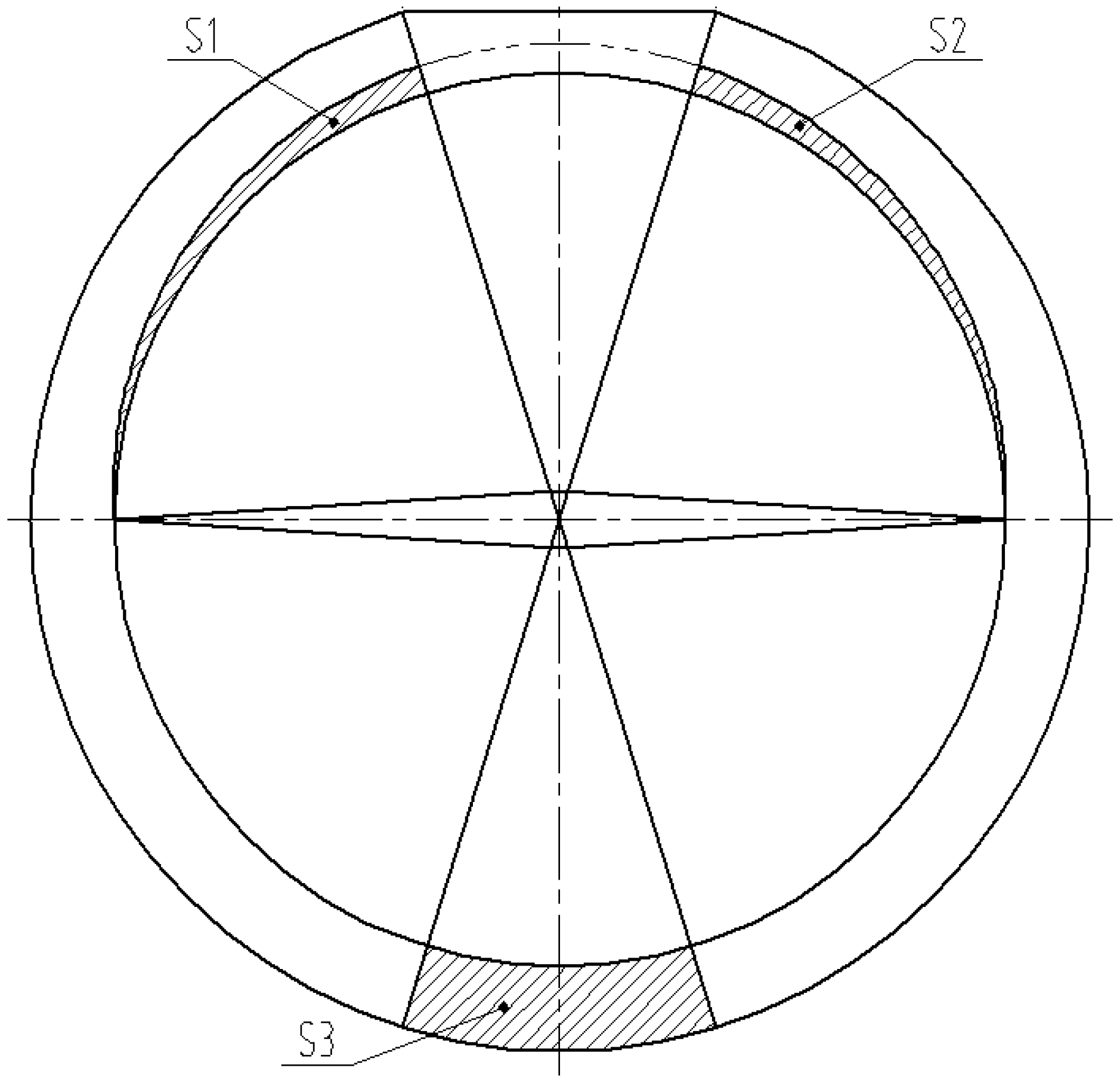
2. Theoretical Analysis and Scheme Design

At present, the ideal structure of the volute of the nuclear reactor coolant pump is mainly the symmetrical annular volute. The structure has the following three advantages: (1) it is easy to manufacture; (2) high bearing capacity of the annular structure; (3) the radial force of the rotor system is uniform. However, in practical application, the existence of the outlet pipe not only destroys the original internal flow rule of volute, produces larger vibration force and causes the vibration and noise in the unit, but also causes the asymmetrical distribution of pressure in the volute and produces larger radial force, which affects the operation life of the pump unit. Therefore, it is necessary to optimize the design of annular volute on the basis of original structural design to ensure the smoothness of internal flow and balance to eliminate radial force. This paper mainly uses the eccentricity produced by the center line of the impeller and the central line of the annular volute to eliminate the adverse effects of the outlet pipe on the annular volute.
From Figure 1, it can be seen that the fluid at the junction between the outlet pipe of the annular volute and the volute has no pressure on the pump case, and the pressure of the fluid on the pump shell corresponding to the position of the outlet pipe (the S3 region in Figure 1) is the main factor of the radial force. Using the hydraulic design method of the central line of the annular volute and the center line of the impeller (the downward eccentric delta of the impeller center line), the pressure from the eccentricity (S1, S2 region in Figure 1) is used to balance the pressure at the relative position of the outlet (the S3 region in Figure 1). The pressure at the rest of the annular volute is offset in the radial direction. For the pressure formed at two positions of S1, S2, the horizontal direction counteracts each other, and the direction of the synthetic pressure is vertically upward to balance the pressure at the S3.
The areas S1, S2 and S3 are used to approximate the representation of the pressure. As such, to balance out the radial force, we just have to make the relation among them to meet Equation (1):
0.9 S 3 S 1 + S 2 1.1 S 3
In order to ensure the eccentricity schemes are conducted when the impeller, guide blade, water chamber, and the layout of the outlet section are invariable, move the pump casing to the pump outlet section for a distance e (The eccentricity is defined as the difference between the centerline of the impeller and the centerline of the volute. As shown in e in Figure 2. unit: mm), and the impeller, guide blade and inlet section remain at the original position. The eccentricity scheme of the nuclear reactor coolant pump is shown in Figure 3. The influence of eccentricity on the head, radial force, and axial force of the nuclear reactor coolant pump in cavitation under five schemes of eccentricity e = 0 mm, e = 5 mm, e = 10 mm, e = 15 mm, and e = 20 mm is studied.

3. Numerical Simulation

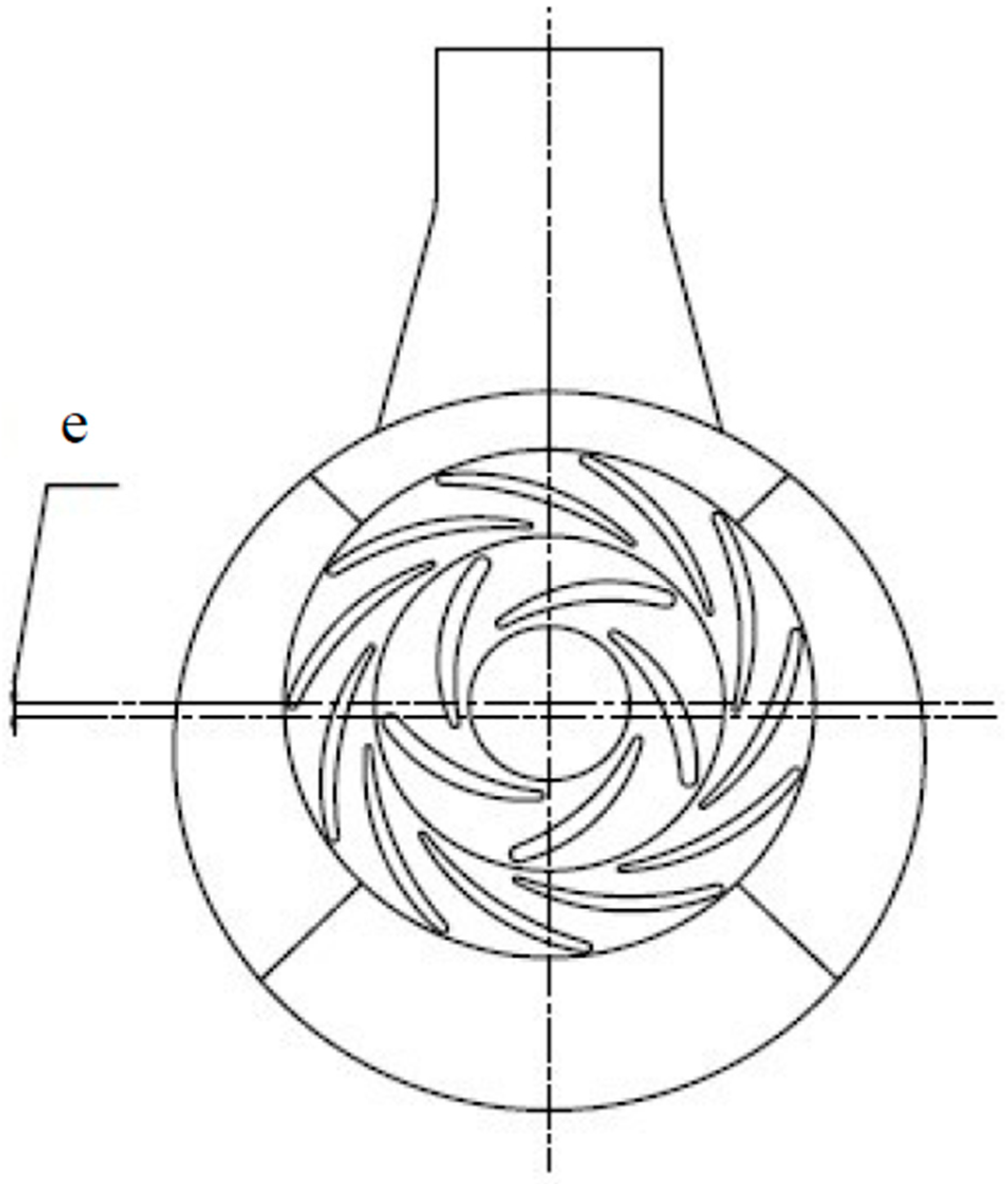
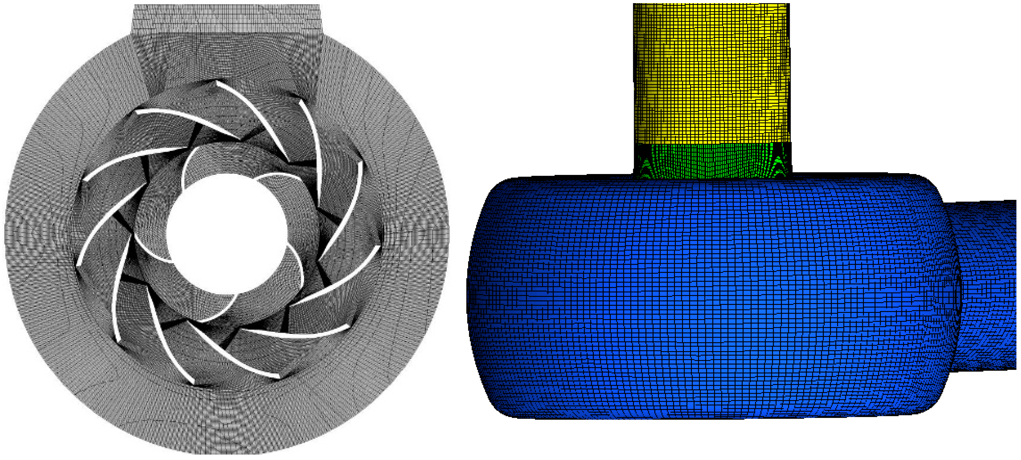
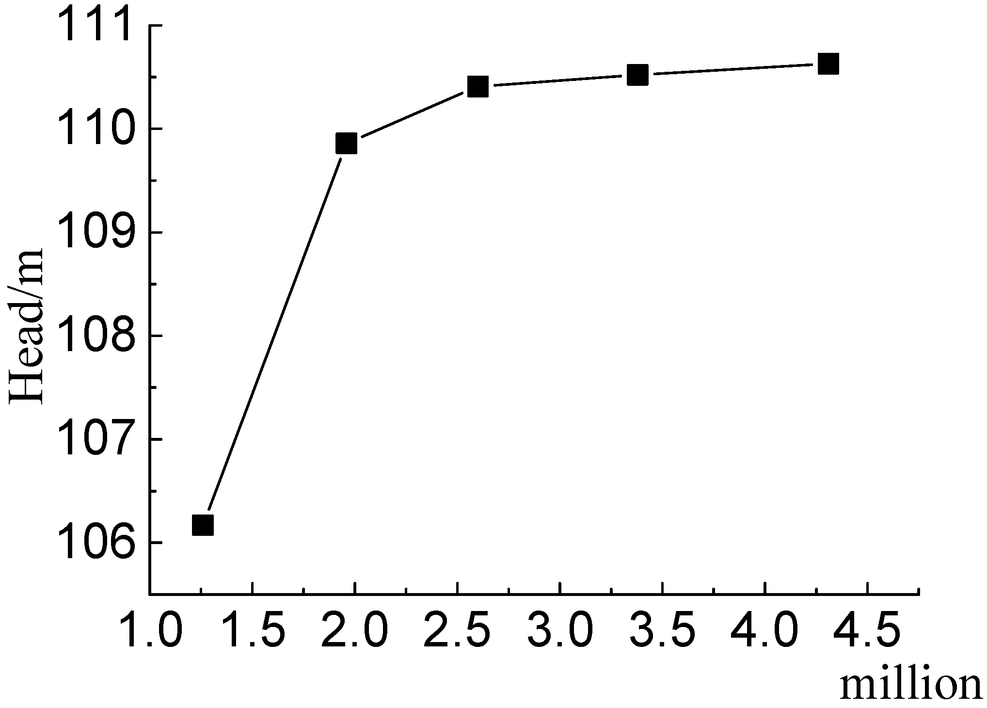
3.1. Computing Model and Grid Partition

The object of this study is the AP1000 nuclear reactor coolant pump with a vertical single stage single suction mixed flow pump. The conveying medium is clean water. In order to ensure the accuracy and reliability of the numerical simulation, the size of the prototype pump is reduced and tested. The main parameters of the prototype pump are shown in Table 1, and the main parameters of the model pump after conversion are shown in Table 2. The rotor is a cantilever structure, and a radial guide blade is arranged outside the impeller to make the fluid uniformly enter the annular volute.
PRO/E software is used to generate the 3D calculation area model. The main water body of the whole pump are in turn entrance, impeller, guide blade, pumping chamber, and outlet section. The hexahedral structure meshing of the overflowing parts of the nuclear reactor coolant pump is carried out by ICEM CFD. The 3D modeling and grid of the water body of the nuclear reactor coolant pump are shown in Figure 3.
In order to ensure that the structural grids of all parts of the above partition meet the needs of computation, the grid independence of the model is tested. In this paper, there are five schemes, but three schemes of different density and grid size are used for the grid division of the water parts of the nuclear reactor coolant pump, and three groups of calculation schemes are obtained. The number of grids are 1.26 million, 2.60 million, and 4.31 million, respectively. The head from the three sets of calculations is shown in Figure 4. It can be seen from the Figure 4 that when the number of schemes 1 grid is adopted, the calculation head of the pump is 106.17 m, and the calculation head is 110.41 m when scheme 2 is adopted, and the calculation value of the head of scheme 3 is 110.63 m. It can be seen that when the number of water grids exceeds 2.60 million, the change of the head of the pump at the rated operating point will be less than 0.5%, and the number of excess grids will occupy a large number of computer resources, which requires a higher configuration computer and takes a long time to ensure accuracy and economic efficiency. Thus, the grids are more suitable to approximate 2.60 million, and the structural grid of scheme 2 is adopted in this paper.

3.2. Numerical Calculation Method and Boundary Condition

The steady state calculation of cavitation is carried out through ANSYS CFX software, and the total inlet pressure corresponding to the critical cavitation, severe cavitation and fracture cavitation of the nuclear reactor coolant pump is carried out. The impeller, as a rotating part, adopts a rotating coordinate system, and the definition domain is set as Rotating domain. The rotation speed of the impeller is set as 1480 r/min. There are three main interfaces to be set in this paper, namely the interface of inlet section-impeller, impeller-guide vane, and guide vane-volute, which are set as the Frozen Rotor. The steady-state calculation results of the three cavitation conditions are taken as the initial conditions of the unsteady state calculation, and the RNG k-ε turbulence model and two fluid two phase flow model are used to calculate the results. The interface in the unsteady state calculation is set to Transient Rotor-Stator mode, and in the simulation, the rotation time of the impeller is 60/1480 = 0.0405 s, and the time step of the unsteady numerical simulation is 3.378 × 10⁻³ s (the time of impeller’s turning over 3°), and the total time is 0.24324 s.
The inlet condition is the total pressure inlet, and the outlet condition is the given outlet mass flow. The flow rate of the model is calculated by controlling the outlet boundary conditions. The standard wall function is used in the near wall surface. The wall boundary condition is adiabatic and non-slip wall; the average diameter of the bubble is set to 2 × 10⁻⁶ m, the volume fraction of water at the inlet is set to 1, and the volume fraction of the bubble is set to 0.

4. Calculation Results and Analysis

Figure 5 is the testing site and the performance curve compared between the experimental results and the simulation results. It is shown by the diagram that the maximum efficiency point of the pump appears at the design point. After 1.2 Qn, H and η begin to fall sharply with the increase of flow, and the cavitation may have developed to a considerable extent at this time.

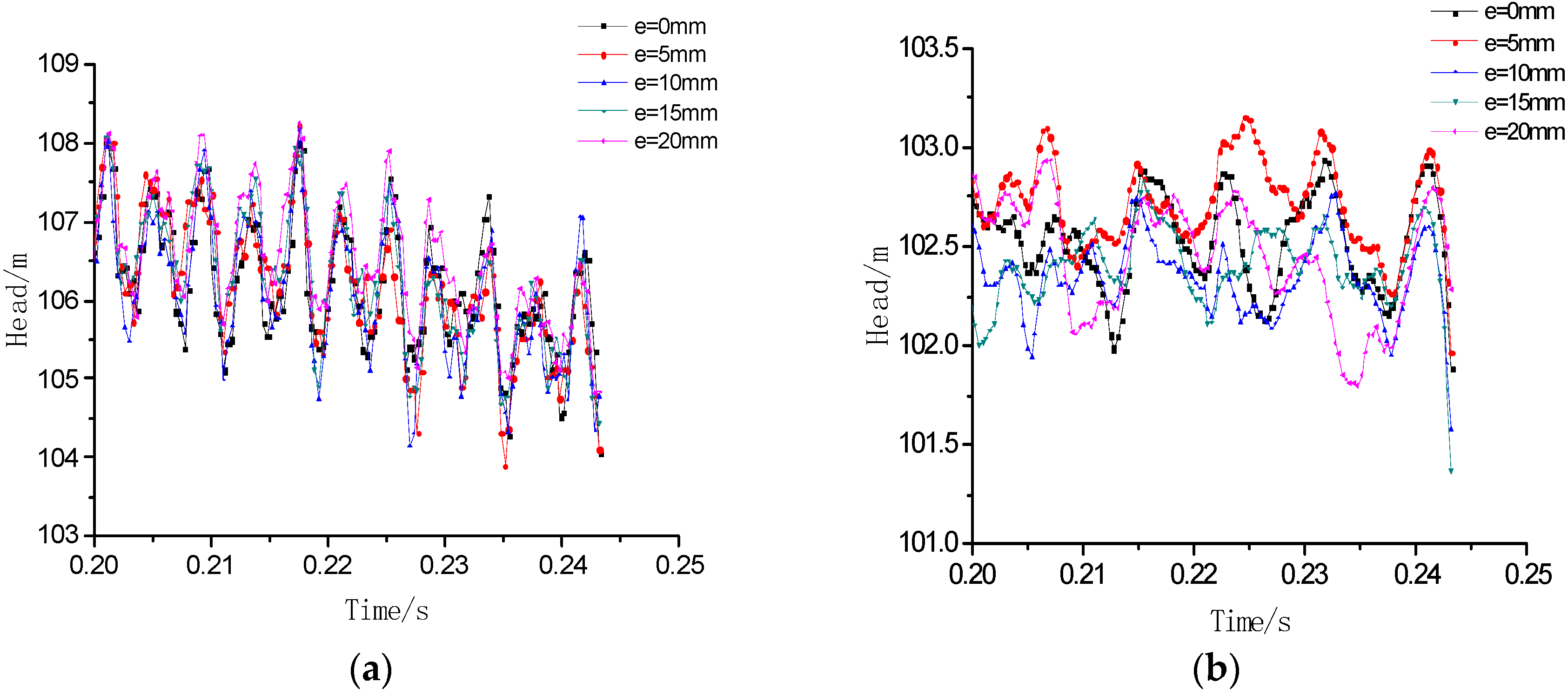
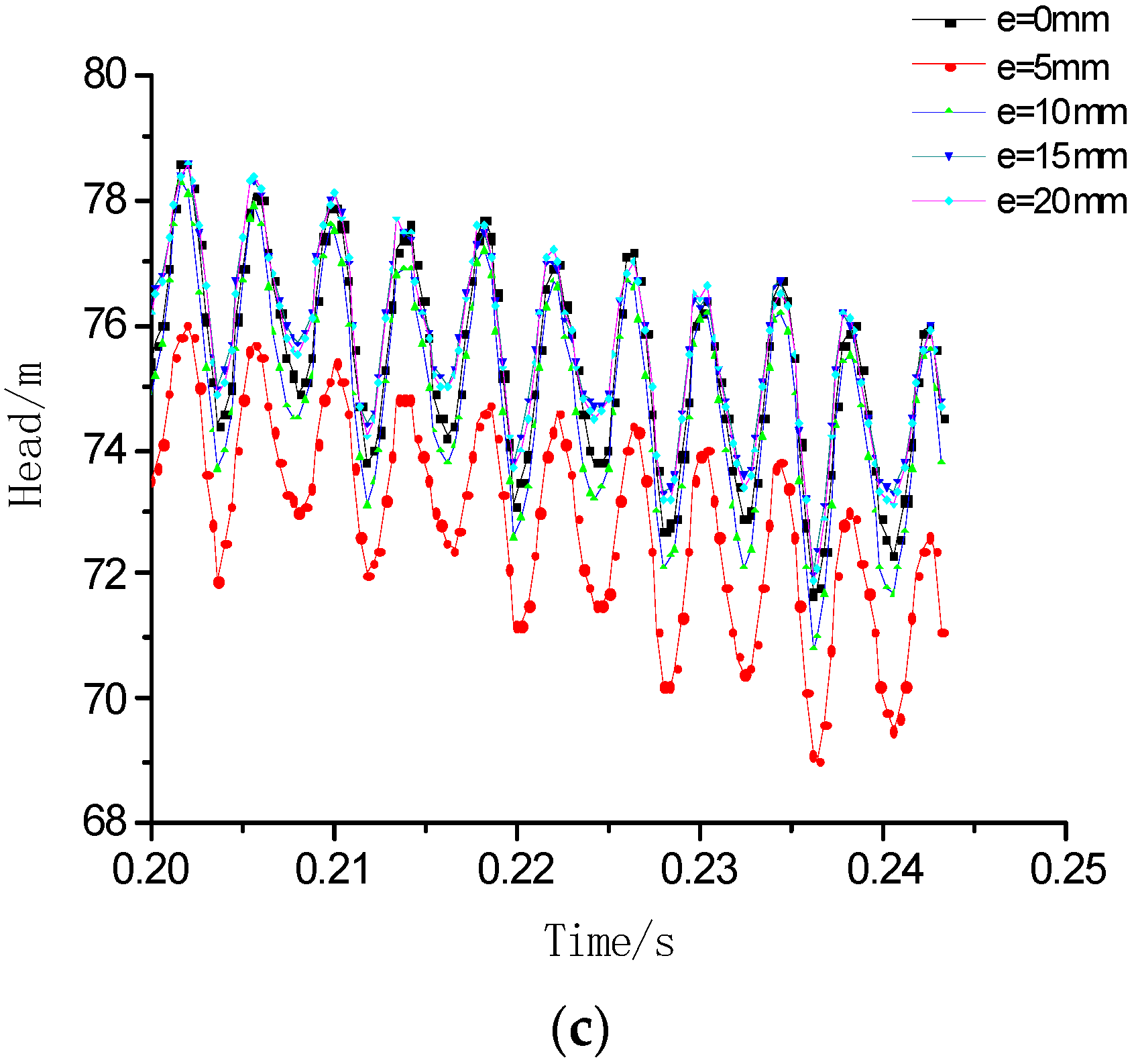
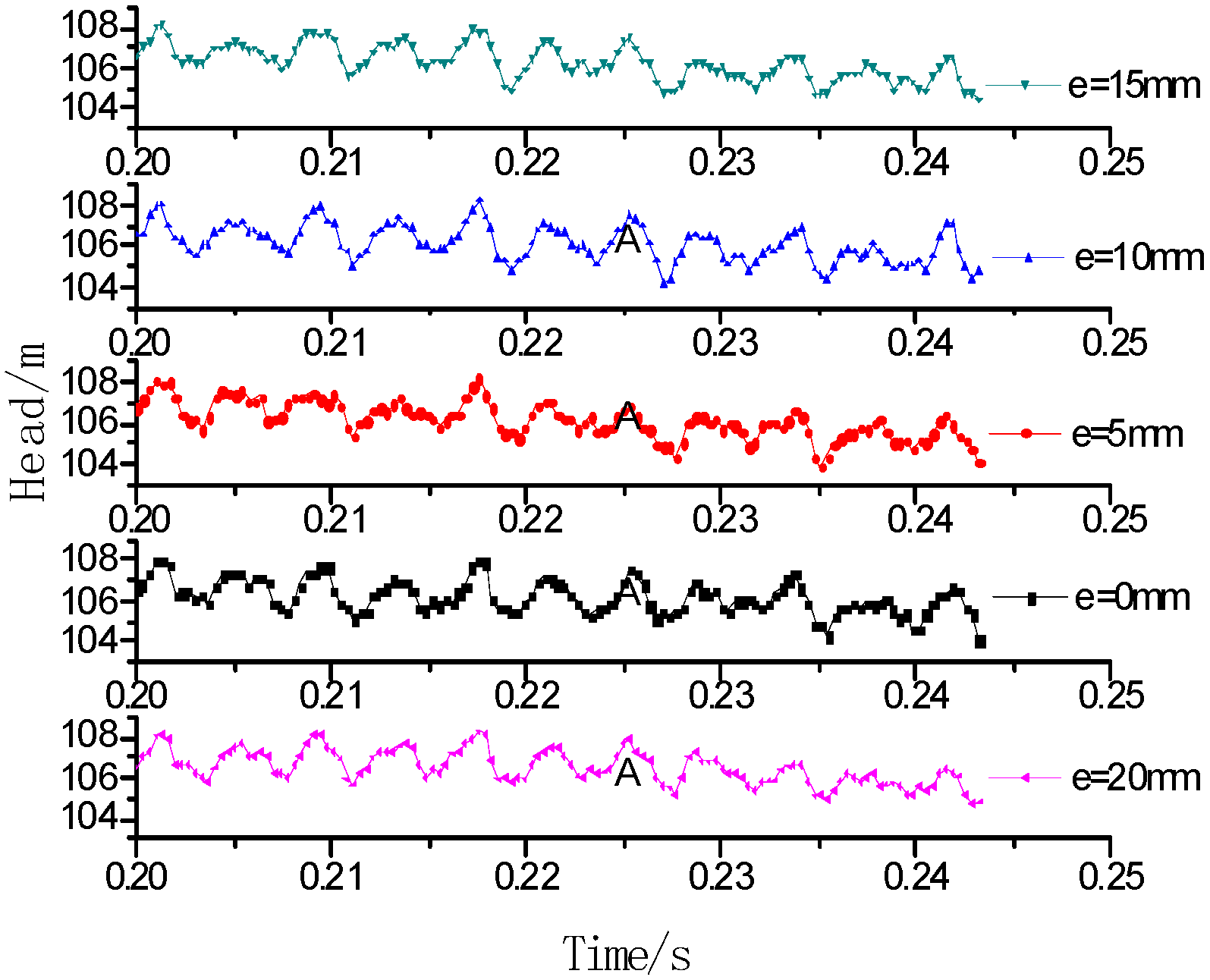
4.1. The Effect of Eccentricity on the Head

Through the steady numerical simulation and analysis to the nuclear reactor coolant pump model, the three inlet total pressure are selected as 140 kPa, 110 kPa, and 100 kPa respectively in this paper. On the basis of the three groups of steady-state calculation results, the unsteady numerical simulation of the cavitation of the pump is carried out, and the change curves of the three groups of pump head at any time in Figure 6 are obtained. In order to ensure the accuracy of the calculation results, all the curves in Figure 6 take the data of the last cycle of the calculation cycle for drawing.
Figure 7 is a vapor phase volume fraction diagram of three different inlet blades under eccentric e = 0 mm. The volume fraction distribution of vapor phase in each eccentric scheme is similar, so here we take only as an example.
To better illustrate the different characteristics between curves in Figure 6a, we will divide the five curves in Figure 6a into a hierarchical graph, as shown in Figure 8. The five curves from top to bottom are eccentricity e = 15 mm, e = 10 mm, e = 5 mm, e = 0 mm, and e = 20 mm in turn.
When the total inlet pressure of the calculation model is 140 kPa, cavitation occurs inside the nuclear reactor coolant pump, and the head of the nuclear reactor coolant pump will fluctuate around 107 m. As shown in Figure 8, the head of each eccentric schemes decreases by about 3.8% during the cavitation stage in contrast with the stage of conveying single-phase liquid. Through Figure 7, it can be found that the area of the air bubble in the impeller is small, the volume fraction of the gas in the region is low, the effect of the slight cavitation on the normal transport of the coolant is small at the moment, and the critical cavitation stage is defined.
In Figure 6b, the difference of head curves is increased under the eccentricity schemes. When the total inlet pressure is 110 kPa, the head is about 102.5 m, which is 8% lower than that in the non-cavitation state. Figure 8 shows that at this stage, the cavitation area of the impeller increases and the volume fraction of gas increases. The blockage of bubbles in some of the impeller channels has obviously affected the transportation of coolant. Comparing the curves in Figure 6b, the head in the scheme of eccentric distance e = 5 mm is higher than that of the original plan. The cavitation state is defined as a severe cavitation.
Figure 6c corresponds to the head curve in each eccentric scheme under the total inlet pressure of 100 kPa. At this moment, the pump head is only 75 m, which is reduced by more than 33%. As can be seen from Figure 8, a large number of bubbles are gathered in the impeller channel, which will block the flow of coolant and seriously affect the safe operation of the nuclear reactor coolant pump. From the cavitation performance curve, it can be found that at this time the pump head presents a fracture type descent, so the cavitation condition is defined as fracture cavitation. According to Figure 6c, in the scheme with eccentricity e = 5 mm under fracture cavitation, head was obviously lower than that of the other groups, while the other groups of heads maintained a high consistency.

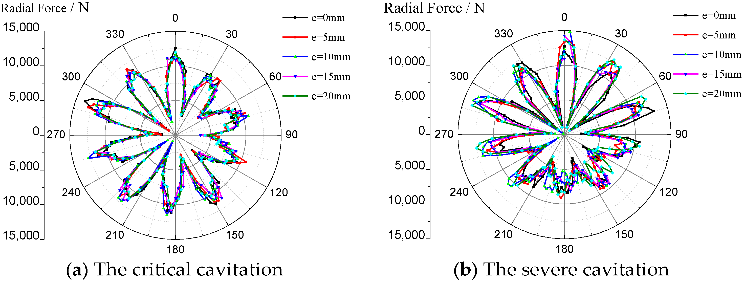
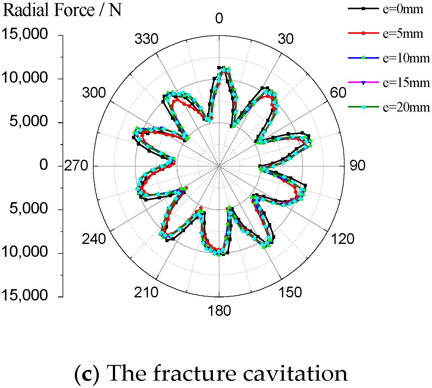
4.2. The effect of Eccentricity on the Radial Force of the Impeller

Figure 9 is the polar diagram of the resultant of radial force distribution on the impeller under different conditions of critical cavitation, severe cavitation and fracture cavitation.
The last cycle of each unsteady solution is selected for analysis. Each curve is composed of 120 data points connected by smooth lines. The value of each point in the curve represents the resultant force of the radial force at a certain point in the direction. The matching relationship between the impeller and guide blade is consistent at each 0° curve. Observing the above three pictures, we can see that the radial force direction of the impeller changes 10 times periodically in one cycle. Under the critical cavitation condition, the maximum radial force of the impeller is about 10 kN when rotating between 30°and 150°, and the minimum value is about 4 kN. As the impeller continues to rotate, the maximum radial force increases first and then decreases, reaching a maximum value of 13.7 KN in the 290° direction. In this process, the minimum radial force decreases correspondingly, and the radial force of eccentric scheme 10 mm is about 1 kN.
When cavitation develops to severe cavitation, the radial force changes more sharply during the rotation of the impeller. The variability of radial force on the impeller between 90° and 240° is less than that in other directions, and the peak value of the radial force in the adjacent four cycles is close, and the periodic variation of the original radial force of the original scheme eccentricity e = 0 mm is not obvious. The difference between the eccentricity schemes is increased, and the difference is mainly reflected in two aspects: first, the maximum radial force of each scheme appears in different directions; second, the difference of radial force increases in the same direction. Under the severe cavitation condition, the radial force change amplitude of the impeller from the initial position to the 90° and the 240° direction to the 360° direction is obviously increased, reaching the maximum value of 15 kN at the initial position, and values in the other directions are slightly larger than the critical cavitation radial force. The minimum radial force in this direction is obviously less than that from 90° to 240°.
When the total inlet pressure is equal to 100 kPa, the nuclear reactor coolant pump is in the state of fracture cavitation. At this point, the influence of eccentricity on the radial force of impeller is weakened. As shown in Figure 9c, the radial force of the impeller shows obvious periodicity during a cycle of rotation, the radial force changes smoothly, and resultant radial force in the range of 0–150° during impeller rotation slightly greater than 150–360° range. The peak value and valley value of each cycle are basically equal, the radial force peak is about 11 kN, and the valley value is about 5 kN.
Comparing Figure 9a with 9b, the minimum radial force decreases as the impeller is rotated to the direction of the radial force that is significantly increased, and the amplitude of the radial force increases. The asymmetric distribution of radial force will aggravate the vibration of the nuclear reactor coolant pump under cavitation condition and threaten the safe operation of the nuclear reactor coolant pump. Moreover, the phenomenon of radial force asymmetry is more prominent in severe cavitation stage. When the internal cavitation of the impeller develops to the fracture cavitation, the radial force asymmetry will be improved. Comparing the three pictures in Figure 9, it is found that the radial force distribution in the fracture cavitation state is better than that in the critical and severe cavitation state. Not only is the variation of radial force smaller, but also the maximum radial force is slightly smaller than the critical and severe cavitation.
In Figure 9c, the position of the radial force peak in each cycle of the eccentricity of 5, 10, 15, and 20 four groups is about 6° clockwise relative to the eccentricity of 0, and the position of the valley value is basically consistent. It shows that the eccentric scheme can change the direction of the resultant radial force on the impeller of the pump. In the critical and severe cavitation state, the phenomenon is not obvious because of the cavitation inside the impeller of the pump.

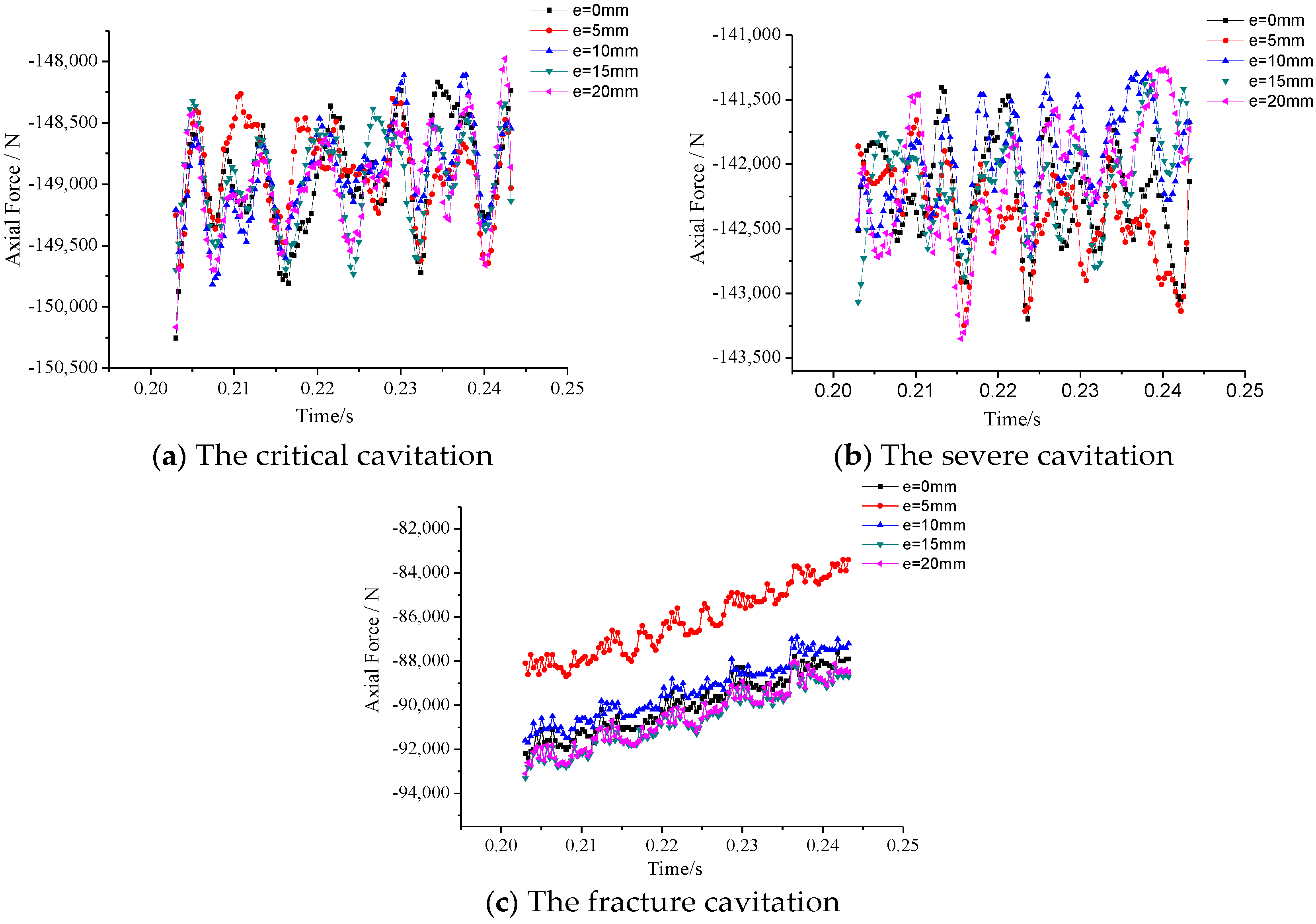
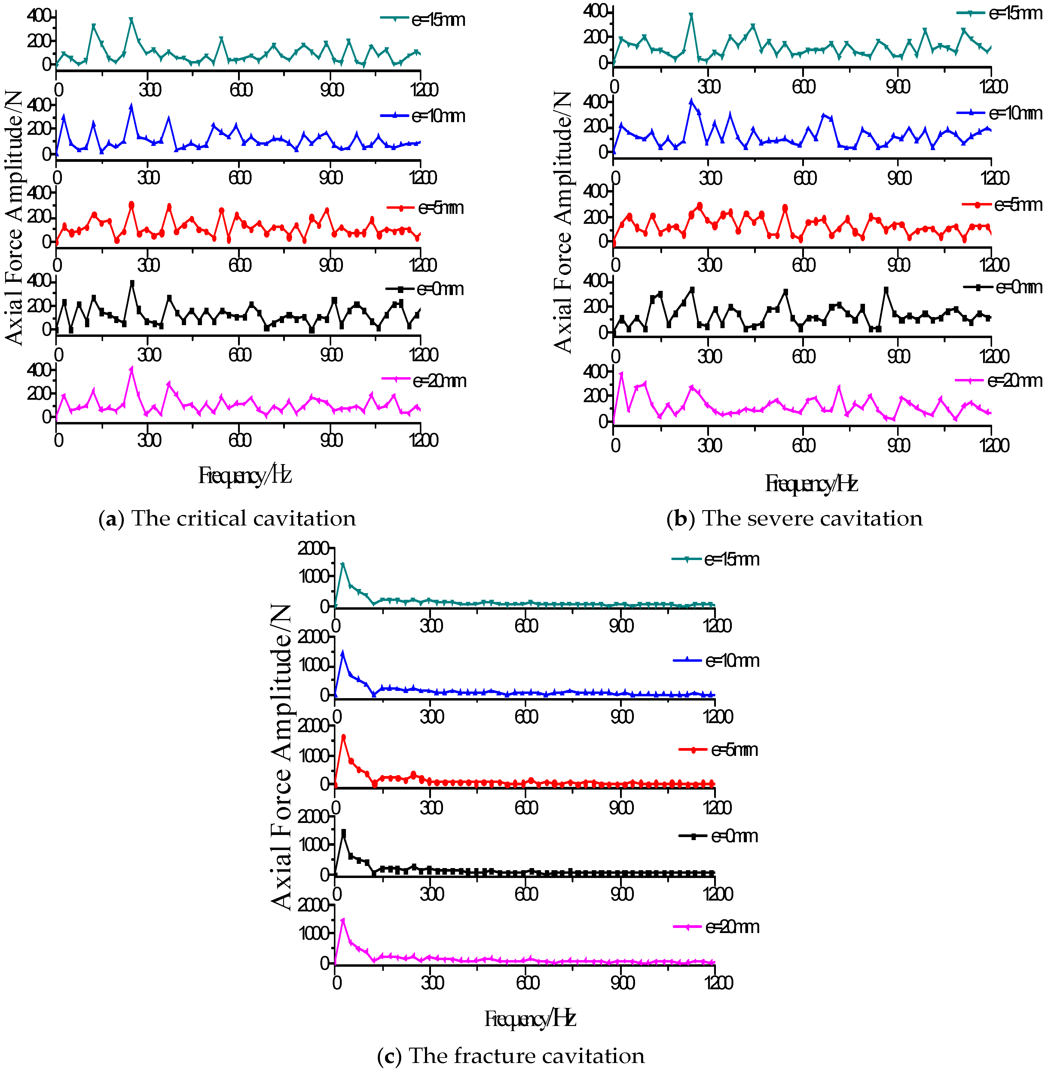
4.3. Influence of Eccentricity on Axial Force of Nuclear Reactor Coolant Pump Impeller

Figure 10 is the time-domain diagram of the axial force of a nuclear reactor coolant pump impeller under different eccentricity and different cavitation conditions. In numerical calculation, the +Z axis is pointed from the front cover plate of the impeller to the rear cover plate. The axial force is negative in the figure, indicating that the axial force direction points to the impeller inlet. As shown in Figure 10, with the deepening of cavitation of the nuclear reactor coolant pump, the axial force of the impeller decreases, and the downward trend increases with the increase of cavitation. The average axial force under critical cavitation is 149 kN, which is 4.7% larger than that under severe cavitation. The axial force decreases linearly in the fracture cavitation, and the axial force is 56.4~61.7% of axial force in critical cavitation state. In Figure 10c, the axial force in the eccentricity e = 5 mm scheme is significantly smaller than that of the other four groups, and the axial force is reduced by 4 kN.
In the fracture cavitation status, the axial force in the two groups of eccentricity e = 5 mm and e = 10 mm is less than that in the original scheme eccentricity e = 0 mm. When the eccentricity e = 15 mm and e = 20 mm, axial forces are basically equal, which are greater than the original scheme eccentricity e = 0 mm. When the impeller is in critical cavitation and severe cavitation stages, the axial force time-domain diagram fluctuates in disorder. Although the axial force changes of each group showed a certain periodicity, the periodic characteristics of each group were obviously different. The difference value between the maximum and the minimum of the axial force in the critical and severe cavitation state when e = 20 mm is the maximum value, and this will lead to the larger vibration of the impeller in the axial direction. It is found that the axial force fluctuation when the eccentricity e = 10 mm is smaller than that of the original scheme, and the curve is distributed above the original scheme curve, indicating that the axial force of the impeller is slightly smaller than in the original scheme.
Figure 11 is the frequency-domain diagram of the axial force of the impeller in the pump under different eccentricity and different cavitation conditions. Table 3 is the frequency and amplitude analysis table of the axial force of the impeller in the pump. In this paper, the impeller speed of the main hydraulic pump model is 1480 r/min and the number of blades is 5. The calculated shaft frequency is 24.67 Hz and the blade frequency is 123.33 Hz. Under the critical cavitation condition, the maximum amplitude of axial force appears at two times of shaft frequency. The maximum amplitude of the five groups of e = 0 mm, e = 5 mm, e = 10 mm, e = 15 mm, and e = 20 mm are 385 N, 306 N, 377 N, 375 N, and 395 N, respectively. There is a larger amplitude at blade frequency and shaft frequency. There is a large amplitude at three times of blade frequency in the four schemes other than e = 15 mm scheme. The vibration is mainly concentrated in the low and medium frequency, and the amplitude decreases after three times of blade frequency. The eccentricity e = 10 mm scheme has the most steady amplitude after two times of blade frequency. The maximum amplitude of the five schemes in the high frequency range is that of the original scheme.
In the severe cavitation condition, the maximum amplitude appears at the blade frequency when e = 20 mm and appears at 2 times the blade frequency in other four schemes. The figures of e = 0 mm, e = 5 mm, e = 10 mm, e = 15 mm, and e = 20 mm show that the maximum amplitudes in each curve are 345 N, 226 N, 398 N, 381 N, and 270 N in turn. The e = 5 mm curve shows low amplitude vibration at all frequency bands. Compared with the other four groups, at all frequency bands of eccentricity e = 5 mm, there has no obvious steady or high amplitude region. The amplitude of the original scheme was 330 N and 343 N at 4.5 times the blade frequency and 7 times the blade frequency and was almost equal to the maximum amplitude of the two times blade frequency, and the rest of the schemes did not appear the fluctuation of the amplitude which is equal to the maximum amplitude in the high frequency range.
Under the condition of fracture cavitation, the maximum amplitude is located at shaft frequency, and the minimum amplitude appears at blade frequency. The amplitude decreases greatly and the vibration is gentle after blade frequency. The maximum amplitudes of each group after 3 times the blade frequency were no more than 150 N, and the vibration was concentrated in the low frequency range. The maximum amplitude of each curve is 1424 N, 1675 N, 1408 N, 1435 N, and 1464 N, respectively.
Through the comparison of the axial force frequency-domain diagram under different cavitation conditions, it was shown that the maximum amplitudes of the critical and severe cavitation conditions were basically equal, and the maximum amplitude of the axial force vibration under fracture cavitation is far greater than that in the other two conditions. As for the overall axial force frequency diagram, with the development of cavitation, the amplitude of axial force vibration increases. In the same cavitation state, the difference in frequency-domain between different eccentricity schemes is obvious, and the vibration characteristics of each curve are not consistent in the full frequency range. The same eccentricity scheme also shows different rules under different cavitation states. Taking eccentricity e = 5 mm, e = 10 mm, e = 15 mm as an example, and the vibration in low frequency range of e = 10 mm and e = 15 mm under critical and severe cavitation state is larger than that of e = 5 mm, while the amplitude of the e = 5 mm scheme at the shaft frequency under fracture cavitation is much larger than that of the e = 10 mm and e = 15 mm two groups. Combined Figure 10 with Figure 11, it can be found that when the eccentricity is e = 5 mm, the axial force of the impeller is smaller than the other three schemes. The amplitude of the whole frequency band under critical and severe cavitation state is smaller than that at the shaft frequency of the other groups, except for the amplitude at the shaft frequency in the fracture cavitation stage, which was a larger one.

5. Conclusions

In this paper, through the steady and unsteady numerical simulation of the internal flow field of the nuclear reactor coolant pump under three different cavitation states, the change rules of cavitation characteristics, radial force and axial force of the pump under different eccentricity are studied. The following conclusions are drawn:
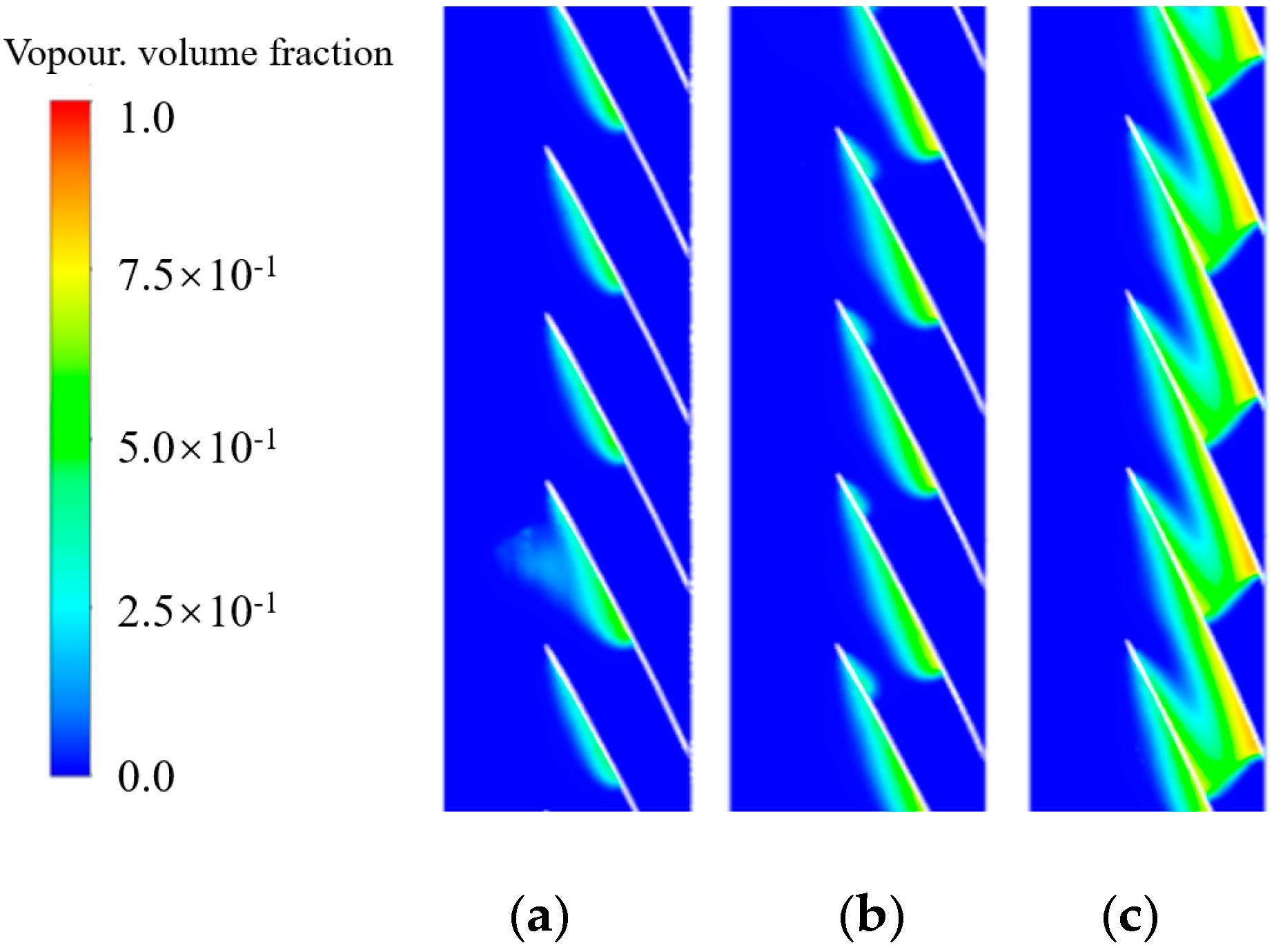
  • The influence of different eccentricity on the cavitation performance of the nuclear reactor coolant pump is obvious, and the effect is increased with the aggravation of cavitation condition. Under the condition of fracture cavitation, the influence on head is the greatest when the eccentricity is 5 mm.
  • Under the critical and severe cavitation conditions, the radial force of the rotor system varies greatly with the impeller rotation, and the radial force variation of the rotor system under the fracture cavitation condition is more uniform.
  • Under severe cavitation conditions, the difference of eccentricity schemes is most significant in the range of 90 to 240 degrees. Under fracture cavitation condition, when the eccentricity is 5 mm, 10 mm, 15 mm, and 20 mm respectively, the position of the radial force peak is about 6 degrees clockwise as to the 0 mm scheme, and the position of the valley value is basically unchanged.
  • Under critical and severe cavitation conditions, the maximum axial force amplitude of the nuclear reactor coolant pump appears at 2 times of the blade frequency and occurs at shaft frequency under the condition of fracture cavitation. Under the condition of fracture cavitation, the corresponding axial force amplitude is much larger than that in critical and severe cavitation conditions.
  • When the nuclear reactor coolant pump is in the critical and severe cavitation condition, the axial force fluctuates most when the eccentricity is 20 mm, and the axial force amplitude is smaller when the eccentricity is 10 mm, and the axial force is smaller than that in the original scheme. In the fracture cavitation condition, when the eccentricity is 5 mm, the axial force of the rotor system is the least, but the amplitude of the axial force is the largest at the shaft frequency. The obtained results can provide reference for the design of new nuclear main pumps.

Author Contributions

Y.Z.: Experiments and simulations; B.L.: modification of the paper; X.W.: ideas and funding acquisition; R.Z., Q.F.: experimental and simulated data processing. All authors have read and agreed to the published version of the manuscript

Funding

National Key Research and Development Project (2018YFB0606105); “Supported by the Open Research Fund of Key Laboratory of ministry (provincial), (Sanxia University)” (2017KJX14); National Natural Science Foundation of China (51379091); National Youth Natural Science Foundation of China (51509112); Key R&D programs of Jiangsu Province of China (BE2016160, BE2017140, BE2018112); Natural Science Foundation of Jiangsu Province of China (BK20171302); Prospective joint research project of Jiangsu Province (BY2016072-02); The China Postdoctoral Science Foundation Funded Project (2019M651734); National Youth Natural Science Foundation of China (51906085) Key R&D programs of Anhui Province of China (201904a05020070); Key R&D programs of Taizhou City (TG201918).

Conflicts of Interest

The authors declare no conflict of interest.

References

  1. Wang, Q.; Chen, X.; Xu, Y.C. Accident like the Fukushima unlikely in a country with effective nuclear regulation: Literature review and proposed guidelines. Renew. Sustain. Energy Rev. 2013, 17, 126–146. [Google Scholar] [CrossRef]
  2. Wang, Q.; Li, R.; He, G. Research status of nuclear power: A review. Renew. Sustain. Energy Rev. 2018, 90, 90–96. [Google Scholar] [CrossRef]
  3. Hong, Z.W. Research on Primary Pump Seal Leakage Abnormality of Data Bay Nuclear Power Station. Master’s Thesis, Shanghai Jiao Tong University, Shanghai, China, 2009. [Google Scholar]
  4. Bo, J.H.; Wang, F. Review on research of small break loss of coolant accident. Chin. J. Nucl. Sci. Eng. 1998, 2, 172–179. [Google Scholar]
  5. Hong, F.; Yuan, J.P.; Zhang, J.F.; Lu, J.; Zhang, Y.; Research Center of Fluid Machinery Engineering and Technology, Jiangsu University. Numerical analysis of cavitating flow characteristics in residual heat removal pumps during the SBLOCA. J. Harbin Eng. Univ. 2015, 3, 297–301. [Google Scholar]
  6. Adamkowski, A.; Henke, A.; Lewandowski, M. Resonance of torsional vibrations of centrifugal pump shafts due to cavitation erosion of pump impellers. Eng. Fail. Anal. 2016, 70, 56–72. [Google Scholar] [CrossRef]
  7. Bo, J.H.; Jiang, S.Y.; Yao, M.S.; Tong, Y.; Zhang, Y.; Wu, S. Simulation experiment of small break LOCA in upper plenum. Nucl. Power Eng. 1990, 5, 57–60. [Google Scholar]
  8. Lu, P.B. Analysis of Cavitation Flow in HTHP Mixed-Flow Pump and Influence on Structure Design. Master’s Thesis, Dalian University of Technology, Dalian, China, 2012. [Google Scholar]
  9. Zhang, Y. Numerical Simulation and Cavitation Analysis of the Flow in Nuclear Cooling Pump of Pressurized Water Reactor. Master’s Thesis, Zhejiang University, Hangzhou, China, 2011. [Google Scholar]
  10. Wang, Y.M. The Cavitation Performance Analysis and Assessment of a Mixed Flow Pump Designed with Model Transformation Method. Master’s Thesis, Dalian University of Technology, Dalian, China, 2013. [Google Scholar]
  11. Wang, X.L.; Wang, P.; Yuan, S.Q.; Zhu, R.S.; Fu, Q. Analysis on transient hydrodynamic characteristics of cavitation process for reactor coolant pump. At. Energy Sci. Technol. 2014, 8, 1421–1427. [Google Scholar]
  12. Shi, W.D.; Zhang, L.; Chen, B.; Jiang, T.; Zhang, H. Influence of gap on pressure pulsation and radial force of centrifugal pumps. J. Drain. Irrig. Mach. Eng. 2012, 3, 260–264. [Google Scholar]
  13. Wang, P.; Yuan, S.Q.; Wang, X.L.; Yin, T. Numerical analysis on effects of nuclear main pump radial force under different eccentricities. J. Drain. Irrig. Mach. Eng. 2015, 6, 461–466. [Google Scholar]
  14. Meng, L.; He, M.; Zhou, L.; Yang, J.; Wang, Z.; Karney, B.W. Influence of impeller-tongue interaction on the unsteady cavitation behavior in a centrifugal pump. Eng. Comput. 2016, 33, 171–183. [Google Scholar] [CrossRef]
  15. Tao, R.; Xiao, R.; Wang, F.; Liu, W. Cavitation behavior study in the pump mode of a reversible pump-turbine. Renew. Energy 2018, 125, 655–667. [Google Scholar] [CrossRef]
  16. Fu, Q.; Zhang, F.; Zhu, R.; He, B. A systematic investigation on flow characteristics of impeller passage in a nuclear centrifugal pump under cavitation state. Ann. Nucl. Energy 2016, 97, 190–197. [Google Scholar] [CrossRef]
  17. Tao, R.; Xiao, R.; Liu, W. Investigation of the flow characteristics in a main nuclear power plant pump with eccentric impeller. Nucl. Eng. Des. 2018, 327, 70–81. [Google Scholar] [CrossRef]
  18. Lu, Y.; Zhu, R.; Fu, Q.; Fu, Q.; An, C.; Chen, J. Research on the structure design of the LBE reactor coolant pump in the lead base heap. Nucl. Eng. Technol. 2019, 51, 546–555. [Google Scholar] [CrossRef]
  19. Lu, Y.; Zhu, R.; Wang, X.; Yang, W.; Qiang, F.; Daoxing, Y. Study on the complete rotational characteristic of coolant pump in the gas-liquid two-phase operating condition. Ann. Nucl. Energy 2019, 123, 180–189. [Google Scholar]
  20. Lu, Y.; Zhu, R.; Wang, X.; An, C.; Zhao, Y.; Fu, Q. Experimental study on transient performance in the coasting transition process of shutdown for reactor coolant pump. Nucl. Eng. Des. 2019, 346, 192–199. [Google Scholar] [CrossRef]
Figure 1. The optimized compensation scheme.
Processes 08 00098 g001
Figure 2. The eccentricity scheme of the nuclear reactor coolant pump.
Processes 08 00098 g002
Figure 3. 3D modeling and grid of the water body of the nuclear reactor coolant pump.
Processes 08 00098 g003
Figure 4. The head for each scheme.
Processes 08 00098 g004
Figure 5. The testing site and comparison between the experimental results and the simulation results.
Processes 08 00098 g005aProcesses 08 00098 g005b
Figure 6. The change curves of the head ((ac) represent conditions with inlet total pressure of 140 kPa, 110 kPa, and 100 kPa respectively).
Processes 08 00098 g006aProcesses 08 00098 g006b
Figure 7. The vapor phase volume fraction diagram of three different inlet pressure condition under eccentric e = 0 mm (ac) represent conditions with inlet total pressure of 140 kPa, 110 kPa and 100 kPa respectively).
Processes 08 00098 g007
Figure 8. The hierarchical graph under the inlet total pressure being140 kPa.
Processes 08 00098 g008
Figure 9. The polar diagram of the resultant of radial force distribution on the impeller.
Processes 08 00098 g009aProcesses 08 00098 g009b
Figure 10. The time-domain diagram of the axial force of a nuclear reactor coolant pump impeller.
Processes 08 00098 g010
Figure 11. The frequency-domain diagram of the axial force of the impeller in the pump.
Processes 08 00098 g011
Table 1. Parameters of the prototype pump.
Designed Q (m3/h)Designed Head H (m)Rotational Speed n (r/min)Specific Speed ns
17,886111.31480351.4
Table 2. Parameters of the model pump after conversion.
Designed Q (m3/h)Designed Head H (m)Rotational Speed n (r/min)Specific Speed ns
114.23.831480351.4
Table 3. The frequency and amplitude analysis table of the axial force of the impeller in the pump.
Cavitation States e = 0 mme = 5 mme = 10 mme = 15 mme = 20 mm
Critical cavitationThe maximum amplitudes (N)355306377375355
Blade frequency (f)3 f3 f2 f2 f3 f
Severe cavitationThe maximum amplitudes (N)345226398381370
Blade frequency (f)2 f2 f2 f2 f1 f
Fracture cavitationThe maximum amplitudes (N)14241675140814351464
Blade frequency (f)1 f1 f1 f1 f1 f
Note: f—the blade frequency.

