1. Introduction
Compared with other transmission modes, hydraulic transmission system has been widely accepted because of its advantages of large power-mass ratio, convenient control, and smooth transmission [
1,
2,
3]. Ultra-high pressure is one of the development directions in hydraulic field at present. Hydraulic pump as the power component of the system, the ultra-high pressure will inevitably have a certain impact on its own structure [
4]. During the operation of piston pump, the friction pairs bears such functions as sealing and lubrication, so the performance of the friction pairs has a key impact on the reliability and service life of the pump [
5,
6,
7]. As the core component of energy conversion of piston pump, the design of piston-cylinder pair is more stringent with the ultra-high pressure of working conditions [
8,
9]. In order to ensure the sealing performance, the distance between piston chambers is only 3–5 mm. Therefore, under ultra-high pressure condition, the failure of oil film of piston-cylinder pair causes many problems. For example, the wear degree between the piston-cylinder pair is aggravated, the volume efficiency is reduced, and the piston is stuck. In order to prevent the above situation of the piston-cylinder pair under ultra-high pressure condition, it is necessary to analyze the oil film characteristics of the piston-cylinder pair. In 1975, Professors Yamaguchi and Takaoka of Japan carried out theoretical and experimental analysis to explore the oil film characteristics of piston-cylinder pair. The motion of the piston is analyzed by perturbation method, and the distribution of the oil film pressure of the piston-cylinder pair is solved. A test-bed is built and the experimental results are compared with the theoretical analysis. The results are basically consistent [
10]. In 1998 Tanaka et al. found that the innovation was the application of displacement sensor and force sensor. By measuring the oil film characteristics and friction characteristics of the piston-cylinder pair, the correctness of the conjecture that the piston rotates around its axis was confirmed. It was also noted that the angular velocity of the piston rotation is similar to that of the spindle [
11,
12,
13]. Xiaofeng He of Huazhong University of Science and Technology established an experimental device for piston-cylinder pair of piston pump in 2001. However, because of the complexity of the motion mechanism of piston-cylinder pair, the experimental device can only be used to evaluate the wear stage of piston-cylinder pair [
14]. Professor Monica I. of Purdue University, USA, has written the CASPAR program. CASPAR program is a tool for calculating the oil film characteristics of the friction pairs clearance of an anisotropic axial piston pump. The hydrodynamic, dynamic, and temperature characteristics of the oil film at the piston-cylinder pair, slipper pairs, and distributor pairs are studied. In 2009, Zhang Bin of Zhejiang University discussed the experimental method based on the oil film characteristics of the piston-cylinder pair under actual working conditions, and established the virtual prototype simulation model of the axial piston pump. The signal is sent to the data acquisition system by the sensor, and the pressure distribution of the piston oil film is tested by the piston oil film characteristic test rig. The experimental results are in good agreement with the simulation results, and the pressure field distribution of the oil film of the piston-cylinder pair can be well displayed [
15]. Professor Bergada of Catalonia University of Technology in Spain has set up a test rig for dynamic oil film pressure of piston-cylinder pair. The test rig is mainly used to analyze the pressure fluctuation of the piston-cylinder pair oil film caused by the change of rotational speed, outlet pressure and inclined plate angle [
16]. Professor Monica I. has built a single piston model pump experiment. The device uses a single piston pump experimental platform with swashplate rotation and fixed cylinder block to measure the oil film lubrication characteristics. Pressure distribution is measured by the pressure sensor, temperature distribution is measured by the temperature sensor, and oil film thickness is measured by the displacement sensor [
17]. Xu Bing and Zhang Junhui of Zhejiang University used virtual prototyping technology to simulate the piston-cylinder pair of axial piston pump. The data transmission of sub-module was carried out by a software, and the fluid-structure coupling and rigid-flexible coupling of the piston-cylinder pair simulation model were also carried out. The validity of the model is verified by the test results, which proves that the virtual prototype simulation platform of the axial piston pump has a strong guiding role in the design of the axial piston pump [
18]. Xu Bing and Zhang Junhui of Zhejiang University describe the piston state of oblique axial piston pump of electro-hydrostatic actuator accurately by solving the discrete oil film Reynolds equation and force balance equation iteratively, and obtain the leakage of piston-cylinder pair under high speed and pressure. It provides appropriate theoretical guidance for the design of EHA pump [
19].
Nowadays, scholars from all over the world have made a detailed study of the piston-cylinder pair. However, because of the limitation of experimental conditions and the consideration of safety when the piston pump speed is too high, the pressure load setting value generally does not exceed 10 MPa. There are few studies on the oil film characteristics of piston-cylinder pair under ultra-high pressure conditions. In this paper, the oil film thickness and pressure characteristics of the piston-cylinder pair of ultra-high pressure piston pump under different working conditions are obtained through mathematical analysis and simulation analysis, and the oil film pressure characteristics of the piston-cylinder pair are obtained through experiments.
2. Analysis of Mechanical Characteristics of Ultra-High Pressure Piston Pump
Figure 1 shows the structure of the ultra-high pressure axial piston pump analyzed in this paper. Its rated working pressure is 70 MPa. The swashplate of the ultra-high pressure piston pump is integrated with the main shaft. It is composed of transmission shaft, pump cover, cycloid pump (refueling), pressure valve screw (valve distribution), and so on. Ultra-high pressure axial piston pump is driven by a motor to rotate the drive shaft, which causes the synchronous rotation of the swashplate and the thrust ball bearing on its surface. The return mechanism tightly compresses the piston ball head with the thrust ball bearing surface, and then drives the piston to move in the axis direction.
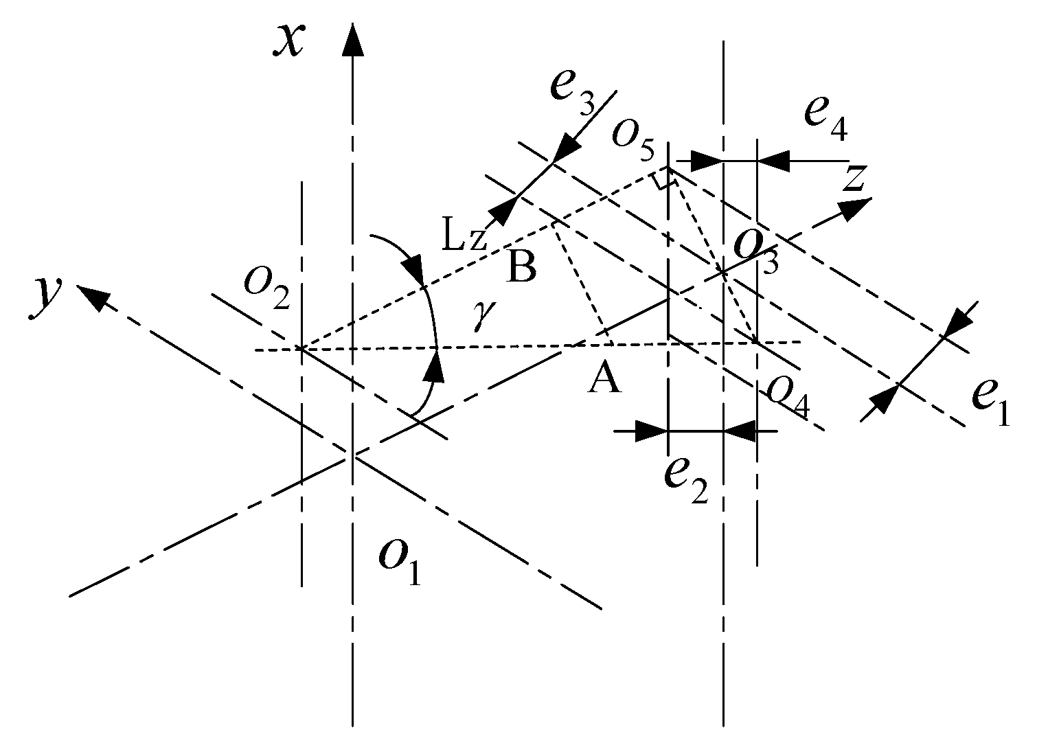
The piston is subjected to hydraulic pressure of oil in the cavity, inertia force of linear motion, viscous friction force, support force of thrust ball bearing, friction force, and self-gravity. When the piston moves under their combined action, the center line of the piston and the center line of the piston cavity will not be in the same line, which will produce a certain deviation as shown in
Figure 2.
In order to describe the inclined state of piston, the attitude inclination degree of piston in piston cavity is represented by introducing (, , , ) and named (, , , ) as offset coordinates. (, ) are near the end of the piston cavity and (, ) are near the piston ball.
The thickness of the piston-cylinder pair at any position in the axial direction of the piston satisfies:
The unknown quantity
in the above formula can be obtained by using cosine theorem for triangle
. The expression of cosine theorem is as follows:
In the formula, is the distance between the center of the piston cavity section and any point on the piston section; is the distance between the center of the piston section and the center of the piston cavity section ; is the angle between the piston center and any point on the piston and the positive direction of the x axis; and is the angle between the center of the piston and the center of the piston cavity and the negative direction of the y axis.
Formula (2) is brought into Formula (1) to obtain:
After simplification, we can get:
is projected in the x-axis direction from the center of the piston section to the center of the piston cavity, is projected in the y-axis direction from the center of the piston section to the center of the piston cavity.
If Formulas (5) and (6) are introduced into the simplified formula of oil film thickness, the expression h of oil film thickness at any point in the axial direction of piston is only a function of and . Therefore, according to the values of and , the oil film thickness at any position in the axial direction under the graphical attitude of piston can be obtained.
The
and
in the above formula are related to the migration coordinates (
,
,
,
). The specific relations between them are as follows in
Figure 3.
The central deviation AB of any point in the axis direction of the piston:
AB projection in horizontal and vertical directions:
The mathematical model of oil film thickness of piston pairs is as follows:
Under the condition of ultra-high pressure, the flow of oil film in piston-cylinder pair belongs to crevice flow. Based on the theory of crevice flow and laminar flow characteristics, the following assumptions are put forward:
(1) Ignoring the proportion of mass force; (2) ignoring the inertial force of fluid; (3) ignoring the curvature of oil film, replacing rotational velocity with translation velocity; (4) ignoring the change of oil film pressure in thickness direction; (5) oil flow velocity and viscosity do not change with the change of oil film height; (6) it is assumed that the curvature radius of the interface contacted with the oil is much larger than the thickness of the oil film.
For incompressible viscous fluids, Navier–Stokes equation (N–S equation for short) characterizes the motion characteristics of fluids and is its differential equation of motion. N–S equation reflects the relationship between mass force, viscous force, and motion parameters of viscous fluid at any point in the flow process. In space rectangular coordinates, the expression of N-S equation is as follows:
In the formula, is the mass force of a fluid with unit mass in the x-axis direction, is the mass force of a fluid with unit mass in the y-axis direction, is the mass force of a fluid with unit mass in the z-axis direction, is the fluid pressure, is the density of fluid, and is the motion viscosity of the fluid.
Under the above assumptions, the simplified N-S equation is:
According to hypothesis (6), the annular oil film of piston pairs is expanded as follows in
Figure 4.
The oil film of expanded piston-cylinder pair is analyzed in Cartesian coordinate system. Because the piston of the ultra-high pressure pump rotates in the direction of the non-winding transmission shaft, and because the motion between the swashplate and the cylinder block is reciprocal. Therefore, in order to express the velocity boundary condition of the oil film of the piston-cylinder pair, the actual situation of cylinder block fixing and swashplate rotating are transformed into that of cylinder block rotating and swashplate fixing.
Mathematical model expression of oil film pressure of piston pairs:
In the formula: is the thickness of the oil film of the piston-cylinder pair; is the viscosity of the oil film of the piston-cylinder pair; P is the pressure of the oil film of the piston-cylinder pair.
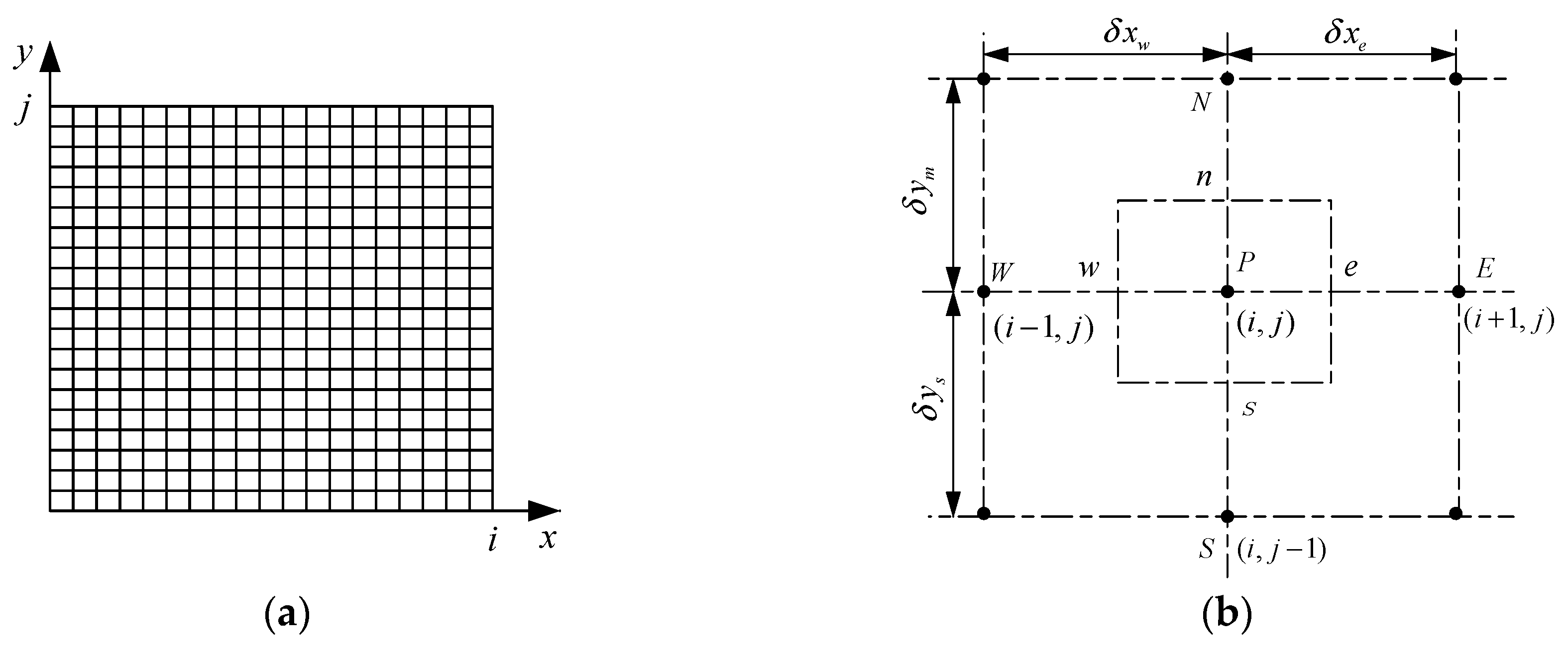
In view of the very small film thickness of the ultra-high pressure piston pump, in order to simplify the solution process, the expanded oil film is equivalent to a plane form. In this paper, the Reynolds equation of oil film is solved by the finite volume method. The expanded oil film is meshed as follows (
Figure 5a). By integrating the Reynolds equation of oil film in each control volume, a set of discrete equations about pressure can be solved. Therefore, by solving the discrete equations, the pressure distribution at each point on the oil film of the piston-cylinder pair under ultra-high pressure can be obtained. Establish a two-dimensional control volume structure as shown in
Figure 5b.
According to the idea of finite volume method, the Reynolds equation of oil film is integrated into the control volume n-w-s-e in
Figure 5b, which is expressed as follows:
The volume integral of formula is transformed into area integral by using the Gauss theorem. The expression of the Gauss theorem is as follows:
In the control volume n-w-s-e, the horizontal e and w points are:
In the control volume n-w-s-e, the vertical n and s points are:
Bring the formula into the formula and simplify it into:
In the formula, is the oil film thickness at point in n-w-s-e, is the oil film thickness at s point in n-w-s-e, he is the oil film thickness at e point in n-w-s-e, and is the oil film thickness at n point in n-w-s-e, is the x-direction length of each micro-grid in the oil film division area of the piston-cylinder pair; is the y-direction length of each micro-grid in the oil film division area of the piston-cylinder pair; is the change rate of the oil film thickness of the piston-cylinder pair with time; and is the motion viscosity of the fluid.
In this paper, the successive over-relaxation iteration method (SOR iteration method) is selected to solve the discrete equation. Over-relaxation method is a modification of the Gauss–Seidel algorithm (GS algorithm). In the iteration process, the results of each iteration and the changes of each iteration are weighted and then brought into the next calculation. Therefore, successive over-relaxation iteration method greatly optimizes the convergence rate. The oil film discrete equation of the piston pairs is substituted into the iteration equation to obtain:
In this paper, the convergence criteria for discrete computation of equations are as follows:
In order to ensure better convergence and calculation accuracy, the convergence accuracy and the value range of relaxation factor are chosen between 1.6 and 1.8.
3. Simulation and Analysis of Oil Film Characteristics of Ultra-High Pressure Axial Piston Pump
In this paper, the oil film characteristics of ultra-high pressure axial piston pump are simulated and analyzed by using the simulation software of MATLAB. In order to compare the oil film characteristics of piston-cylinder pair under ultra-high pressure with those of ordinary medium and high pressure piston pumps, the oil film characteristics of piston-cylinder pair were simulated under 20 MPa and 70 MPa respectively. Parameter settings are shown in
Table 1.
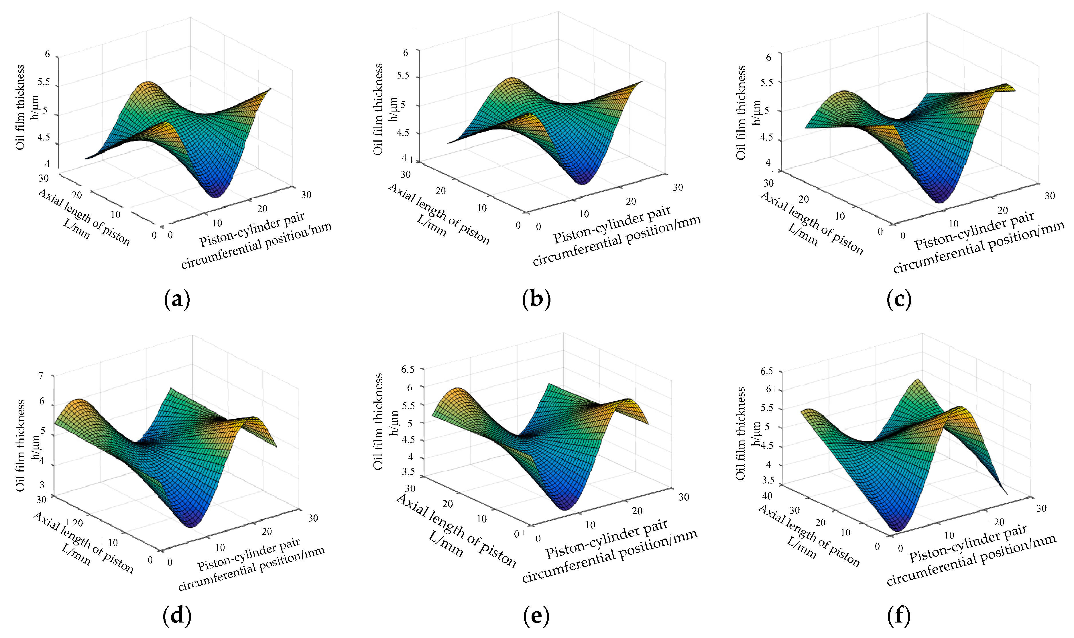
Under constant pressure (20 MPa), the oil film thickness expression of the piston–cylinder pair obtained above is brought into the simulation software of MATLAB, and the results are shown in
Figure 6 (the point of coordinate (0,0) in the figure below corresponds to point A in
Figure 2b).
When the swashplate rotates 1°, the plunger is still near the starting point, the inclination of the plunger is very small, and the oil film thickness is about 5 μm. When the swashplate rotates 10°, the plunger cavity enters the oil pressure area, and the pressure in the plunger cavity increases, resulting in the increase of the eccentric load on the plunger and the increase of the inclination of the plunger. When the swashplate rotates 45°, the eccentric load on the plunger continues to increase, resulting in the increase of the inclination of the plunger. When the swashplate rotates 90°, the movement speed of the plunger reaches the maximum. At this time, the eccentric load of the plunger is the maximum, the inclination degree of the plunger reaches the maximum, the oil film thickness of the cylinder-piston pair reaches the minimum, and the oil film thickness is 3–3.5 μm. When the swashplate rotates 110°, the eccentric load on the plunger is relieved and the inclination of the plunger is reduced. When the swashplate rotates 210°, the plunger enters into the low-pressure oil absorption area, and the degree of eccentric load of the plunger is very small, and the oil film distribution of the cylinder-piston pair is relatively average.
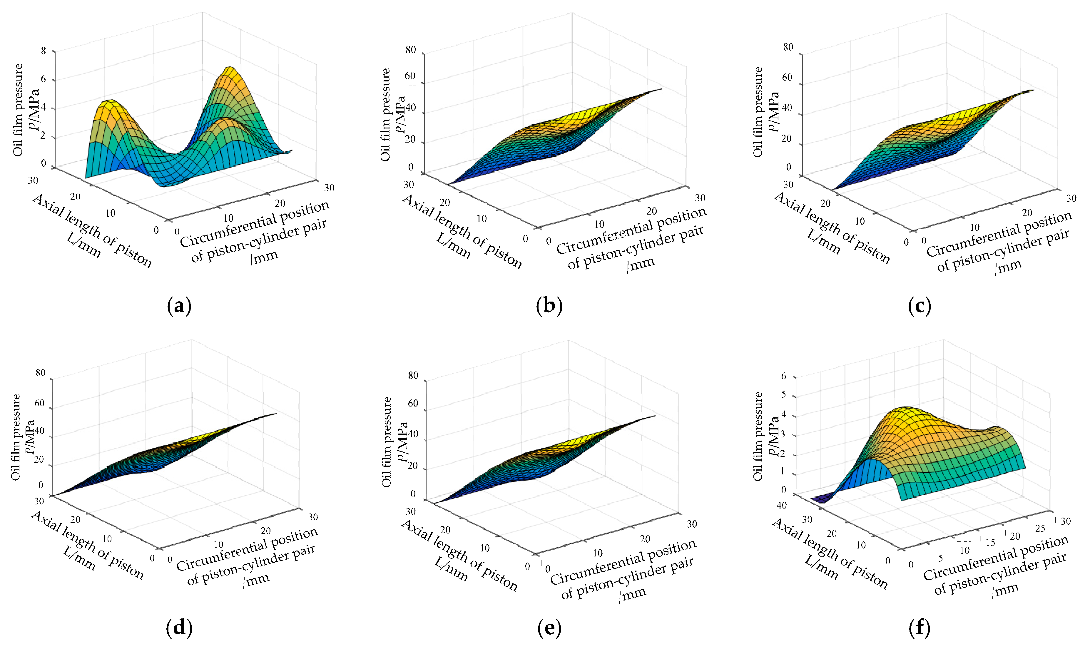
Under constant pressure (20 MPa), the expression of the oil film pressure gauge of the piston-cylinder pair obtained above is brought into the simulation software of MATLAB, and the results are shown in
Figure 7.
When the swashplate rotates 1°, because the plunger is still near the starting point, the pressure in the plunger cavity is not established and the pressure is small. When the swashplate rotates for 10°, the plunger cavity enters the oil pressure area, and the inclination degree of the plunger increases, so the oil film pressure reaches 20 MPa. When the swashplate rotates 45°, with the increase of the pressure in the plunger cavity, the inclination degree of the plunger continues to increase. Therefore, in order to balance the increased eccentric load of the plunger, the oil film pressure continues to increase. When the swashplate rotates to 90°, the movement speed of the plunger is the maximum, the eccentric load degree of the plunger reaches the maximum, and the oil film appears the thinnest area in the whole movement cycle. Therefore, in order to balance the eccentric load, the oil film pressure field of the cylinder-piston pair reaches the maximum, and the oil film pressure reaches 25 MPa. When the swashplate rotates to 110°, the eccentric load on the plunger decreases and the pressure field of the oil film decreases. When the swashplate rotates 210°, the plunger cavity has left the oil pressure area and stepped into the low-pressure oil absorption area. The plunger tends to be in a stable state. Therefore, the oil film pressure distribution is small. The oil film characteristics of the ultrahigh pressure plunger pump studied in this paper are basically the same as those in reference [
15]. When pressing oil, when the inclination of plunger increases, the oil film pressure increases, and when the inclination of plunger decreases, the oil film pressure also decreases. In the process of oil absorption, the pressure distribution of the plunger is also small because of its small inclination. However, the oil film gap of the cylinder-piston pair in this paper is only 5 μm, which is quite different from the oil film gap (17 μm) in reference [
15]. Therefore, although the inclination degree of the plunger will increase, the space (5 μm) for the inclination of the plunger is not as large as that in reference [
15] (17 μm). Therefore, the oil film of the cylinder-piston pair in this paper is squeezed, but the oil film is squeezed membrane pressure does not have a sharp edge. The pressure spike shown in
Figure 8 does not occur.
Under the condition of ultra-high pressure (70 MPa), the oil film thickness expression of the piston-cylinder pair obtained above is brought into the simulation software of MATLAB, and the results are shown in
Figure 9.
Compared with the normal pressure condition, the change trend and distribution of the oil film thickness under the ultra-high pressure condition are the same. Before the swashplate rotates 45°, the oil film thickness is almost the same. But after the swashplate rotates 45°, the oil film thickness under the ultra-high pressure condition is obviously smaller than that under the normal pressure condition. The minimum thickness of oil film is about 2 μm under ultra-high pressure condition. At this time, the bearing limit area appears in the auxiliary oil film of the plunger. The inclination degree of the plunger is greater than that under normal pressure condition, and the failure probability of the auxiliary oil film of the plunger is greater. When the swashplate rotates more than 90°, the oil film thickness under the two conditions is basically the same.
Under the condition of ultra-high pressure (70 MPa), the expression of the oil film pressure gauge of the piston-cylinder pair obtained above is brought into the simulation software of MATLAB, and the results are shown in
Figure 10.
The change trend of oil film pressure under the condition of ultra-high pressure is the same as that under the condition of normal pressure, but there is a big difference in the value. The oil film pressure under the condition of ultra-high pressure is far greater than that under the condition of normal pressure, In this paper, the oil film gap of the cylinder-piston pair of the ultra-high pressure pump is only 5 μm, so whether the oil film thickness is squeezed to 3 μm under the normal pressure condition or the oil film gap is squeezed to 2 μm under the ultra-high pressure condition, the piston tilt space of the two is not large, so there is no pressure spike phenomenon that the normal pressure piston pump will appear when the swashplate rotates 90°.
The oil film thickness and pressure distribution trend of the piston-cylinder pair under 70 MPa condition are basically the same as that under 20 MPa condition. All of them are as follows: when oil is pressed, the axial force of piston increases with the increase of the angle of inclined plate rotation, which leads to the increase of eccentric load on the piston, the increase of piston tilt, and the increase of oil film pressure; when the swashplate rotates at 90°, the axial velocity and force of the piston are the largest, and the eccentric load of the piston is the most serious. The dangerous area of the oil film thickness is less than 3 μm, and the oil film pressure reaches the maximum at this time; when the swashplate rotates at 125°, the axial force acting on the piston is relieved, the inclination degree of the piston is relatively reduced, and the oil film pressure is also reduced. When the piston chamber is sucking oil, the piston tends to be stable and the oil film pressure distribution is small.
4. Experimental Study on Film Pressure of Piston Pairs in Ultra-High Pressure Axial Piston Pump
Because the oil film gap of piston-cylinder pair is very small, the existence of processing errors and the difficulty of installing pressure sensors lead to the measurement of oil film thickness is difficult and the reliability is low, so this paper only tests the oil hydraulic pressure. In the experiment, we choose the way of reforming the solid pump to analyze the oil film of the cylinder–piston pair, and directly measure the pressure of the oil film pair on the solid pump. When selecting the experimental pressure measurement points, the more intensive the experimental measurement points are selected, the more representative the comparison is with the simulation results. Because of the structure of the pump itself, limited by the installation position, the volume of the sensor itself, and the existence of the oil outlet check valve, only one pressure sensor can be installed on the cylinder body for each plunger. In this paper, three pressure measuring points are actually selected on the cylinder block to measure the axial pressure of three different plungers in the same position. Finally, the pressure measurement results of the three measuring points on the cylinder are compared with the simulation results.
Figure 11 is the schematic diagram of the measurement of the oil film pressure of the cylinder-piston pair.
In this section, an experimental platform is designed for the pump, which can provide different load pressures. The experimental platform can complete the measurement of the oil film pressure of the piston-cylinder pair under different load pressures. The principle of the experimental platform is shown in the
Figure 12.
The assembled test device is shown in
Figure 13.
This paper uses NI industrial computer and multi-functional data acquisition system, pressure sensor, measurement and acquisition software LabVIEW, and data processing and analysis in data acquisition software LabVIEW.
The experimental results are shown in
Figure 14.
In order to better compare the test results with the simulation, this paper also simulates the oil film pressure of the plunger pair under the condition of the rated speed of 1500 r/min and the load pressure of 20 MPa and 70 MPa. According to the position of the measurement point in the test, the pressure at the simulation point is connected into a curve, and the simulation pressure curve is shown in the
Figure 15.
According to test
Figure 14 and simulation
Figure 15, the following conclusions can be obtained: (1) The change trend of the test pressure curve is basically the same as that of the simulation pressure curve, showing the trend of first increasing and then decreasing; (2) the test pressure curve shows a triangular trend, and the simulation pressure curve shows a trapezoid like trend, that is to say, when the test pressure curve is pressurized, the pressure rises slowly, and at the same time, it is unable to hold the high pressure; (3) with the increase of the load pressure, the pressure values measured in the test are less than the simulation pressure. The larger the load pressure is, the greater the difference between the pressure values obtained in the test and the simulation results is.
The main reason for the above (2) and (3) phenomena is that the oil drawing hole is processed too much. In the measurement process, when the oil reaches the bottom of the threaded hole where the pressure sensor is installed through the oil drain hole, the excessive diameter of the oil drain hole will cause the oil to leak along the wall of the threaded hole, causing a large pressure loss and slow pressure growth. In the process of oil pressure, the larger the load pressure is, the larger the oil leakage through the threaded hole wall of the pressure sensor is, and the larger the pressure measurement error is. Therefore, in the test process, with the increase of load pressure, the measured pressure values are smaller.


