Article

Thermal Isolation of a Clean Alloy from Waste Slag and Polymeric Residue of Electronic Waste

Centre for Sustainable Materials Research and Technology (SMaRT), School of Materials Science and Engineering, University of New South Wales (UNSW), Sydney 2052, Australia
*
Author to whom correspondence should be addressed.
Processes 2020, 8(1), 53; https://doi.org/10.3390/pr8010053
Submission received: 7 November 2019 / Revised: 19 December 2019 / Accepted: 20 December 2019 / Published: 2 January 2020
(This article belongs to the Special Issue Gas, Water and Solid Waste Treatment Technology)

Abstract

:
Unprecedented advances and innovation in technology and short lifespans of electronic devices have resulted in the generation of a considerable amount of electronic waste (e-waste). Polymeric components present in electronic waste contain a wide range of organic materials encompassing a significant portion of carbon (C). This source of carbon can be employed as a reducing agent in the reduction of oxides from another waste stream, i.e., steelmaking slag, which contains ≈20 wt%–40 wt% iron oxide. This waste slag is produced on a very large scale by the steel industry due to the nature of the process. In this research, the polymeric residue leftover from waste printed circuit boards (PCBs) after a physical-chemical recycling process was used as the source of carbon in the reduction of iron oxide from electric arc furnace (EAF) slag. Prior to the recycling tests, the polymer content of e-waste was characterized in terms of composition, morphology, thermal behavior, molecular structure, hazardous elements such as Br, the volatile portion, and the fixed carbon content. After the optimization of the ratio between the waste slag (Fe source) and the waste polymer (the carbon source), the microstructure of the recycled alloy showed no Br, Cl, S, or other contamination. Hence, two problematic and complex waste streams were successfully converted to a clean alloy with 4 wt% C, 4% Cr, 2% Si, 1% Mn, and 89% Fe.

Graphical Abstract

1. Introduction

In the early 21st century, rapid advances in technology and short lifespans of devices, machines, and equipment caused the generation of a large volume of waste in different industries, whether in the well-established steelmaking [1] or in the modern electronics sectors [2]. Management of these waste resources is a critical issue for researchers, and approaches to tackle these problems are chiefly dependent on the content and types of valuable materials/elements in the waste and the environmental impacts of the waste [3]. Due to the large-scale production of steelmaking, the amount of generated waste from this process can be more than thousands of tons annually. Such slag byproducts typically contain a significant amount of iron oxide [4], implying that a significant portion of iron is lost along with the disposal of the slag. On the other hand, electronic waste (e-waste) comes from everywhere that humans live. The main issue is the hazardous effect on the environment and humans’ health due to the presence of hazardous elements, such as Cd, Hg, and Pb [5]. Hence, there are clearly various purposes for somehow recycling various wastes, but in all cases, the final product must be worthwhile from an economic viewpoint.
E-waste consists of discarded electronics that contain a variety of materials, including metals, ceramics, and polymers entangled with each other [5]. Many studies successfully recycled e-waste via physical, mechanical, and chemical approaches [6]. Some researchers focused on the metallic content [7] while others worked on the ceramic [8] or polymer portions [9]. However, less research has been performed regarding how to use these separated/recycled wastes for new purposes. In other words, because of the rapid growth in e-waste generation, recycling industries need to obtain potential customers for their recycled products, such as polymeric components recovered from e-waste.
Polymeric components from e-waste contain many different organic materials, including phenoxy resins, polyvinyl acetate, and vinyl chloride [5]. These are thermoset types of polymers, which have limitations in terms of their applications that are hard to degrade compared to thermoplastics [10]. Also, this e-waste emits hazardous dioxins and elements, for instance, Br and Cl [11]. However, a significant portion of these waste polymers is carbon (C) [12], which can be used as a potential source of carbon in the recycling process of other types of waste, i.e., the discarded slag from the steelmaking industry.
Over the last few decades, traditional steelmaking furnaces were replaced by electric-arc furnaces (EAFs) [1]. The byproduct slag from EAF contains ≈15 wt%–20 wt% Fe in the form of Fe2O3 and FeO. Depending on the conditions and efficiency of the process, the Fe [4] and other heavy metal contents, such as Cr [13], can change. Several studies focused on practical applications of EAF slag, such as fiber-reinforced concrete for pavements [14], aggregate in asphalt mixes [13], geo-fill materials [1], and P-removal agents [15]. These applications are innovative and economical; however, original iron ores contain around 60 wt% iron oxide [16] compared to the 20 wt%–40 wt% iron oxide content found in EAF slag. Thus, in order to avoid the continuous depletion of deposit ores (i.e., Fe, Cr, Si, and Mn), the recycling of these waste slags seems to be profitable. Nevertheless, due to the lower Fe content in EAF slag, the activity of C must be higher and traditional methods of using conventional carbonaceous resources (i.e., coke and coal) may not be efficient. Since the usual coals are not very promising when it comes to providing a high activity for the reduction of EAF waste slag, the carbon sourced from the polymer content of e-waste may be an alternative reducing agent. This carbon is much more reactive than coal carbon and the final surface area of the carbon is much higher, which enhances the rate of the reaction [17]. Using high surface area carbon or a gaseous atmosphere, e.g., CO and/or CH4, could efficiently enhance reduction [18]. Another advantage of using polymeric material for reduction is the presence of hydrogen (H) in addition to carbon, which increases the reduction speed and makes it more environmentally friendly, as it ill produces H2O after the process instead of greenhouse gasses.
In this research, the leftover polymeric residue waste of printed circuit boards (PCBs) as a result of the physical-chemical process was used as a source of activated C in the reduction of iron oxide from EAF slag. Fe, Cr, Mn, and a portion of Si were produced from waste EAF slag. Hence, two major streams of industrial solid wastes were combined, and the output was a metallic ferrous alloy contained Cr, Si, and Mn. The major environmental hazards of the e-waste material were also investigated.

2. Experimental

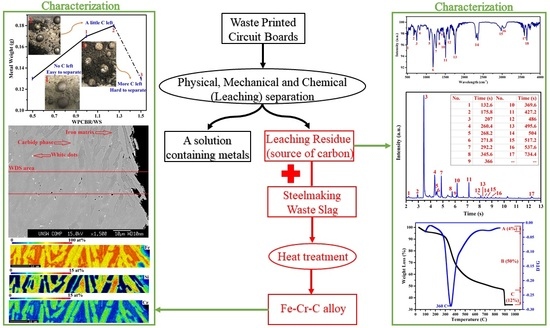
2.1. Feed Materials Preparation and Experiments

Fe source: The source of Fe was from EAF slag as waste material. The delivered slag was crushed into a fine powder (100–200 µm) using a ring mill prior to mixing with a carbon source (i.e., the residue of waste PCBs) for reduction.
C source: The flowchart of the separation process of waste PCBs is presented in Figure 1. Waste PCBs from scrap motherboards were collected from a reverse e-waste company. Polymer slots, capacitors, connectors, the heatsink, backup batteries, the CPU, and the CPU socket of each board were dismantled manually or using a heat gun. The resulting board was sent to be crushed into particles less than 1 mm using ring mill and knife mill in a 3-step process [5]. The crushed powder was then classified into metal-rich and ceramic-rich powders using a sieve shaker (Fritsch, Pulverisette 15) [5]. For the recovery of metal content, the metal-rich powder was treated with acid and all of its metal contents (i.e., Cu, Al, Fe, Sn, Ni, Pb, and Zn) were digested [19]. The resulting solution and the leaching residue were separated by filtration [19]. Lastly, the residue, containing ceramics and polymers, was washed with deionized (DI) water and ethanol using a table-top centrifuge (Hermle Z206 A) for the removal of remaining ions, followed by drying in an oven at 60 °C overnight.
Reduction experiments: To optimize the ratio between the waste slag (WS) and the waste PCB leaching residue (WPCBR), 0.5 g WS was mixed with 0.25, 0.375, 0.5, 0.625, and 0.75 g WPCBR, to provide a W P C B R W S value between 0.5 and 1.5. Each ratio was calculated twice and the average was reported. The mixture was then placed in a zirconia-based crucible located in a graphite rod and gently inserted into a vertical tube furnace under 1 L/min Ar atmosphere at 1550 °C, which was selected based on the kinetics and thermodynamics of steelmaking slag reduction [20]. After 30 min, the sample was discharged from the furnace for manual separation and the weight of the metal droplets was measured. The weight of recycled metal was measured as an indicator of recovery efficiency.

2.2. Characterization

(a)
X-ray diffraction analysis (XRD, PANalytical X’Pert Pro, Malvern, UK) with Cu Kα wavelength and 2θ between 10–100° was applied for phase identification of waste materials and the resulting alloy.
(b)
To increase the precision of phase identification, X-ray fluorescence analysis (XRF, PANalytical PW2400 Sequential Wavelength Dispersive, Malvern, UK) was utilized to quantify the approximate percentage of oxide phases.
(c)
Scanning electron microscopy (SEM, Hitachi S3400, Tokyo, Japan) equipped with energy dispersive spectroscopy (EDS, Bruker) was used for the morphological observation and distribution analysis of elements in the WPCBR.
(d)
LECO analysis was employed to measure the sulfur (S), nitrogen (N) (LECO TruSpec Analyser, Michigan, USA), and carbon contents (LECO CS 444 Analyser, Michigan, USA) of the WPCBR.
(e)
The structural and elemental concentrations of the recycled metal were measured by electron probe microanalysis (EPMA) or wavelength dispersive spectroscopy (WDS, JEOL JXA-8500F) for accurate quantitative mapping and point analysis. The sample was mirror polished and all measured elements were calibrated using standard samples.
(f)
Moreover, the composition of the recycled metal was analyzed using laser-induced breakdown spectroscopy (LIBS, Z-200 under Ar atmosphere), which is known as a very reliable method even for carbon content analysis. The surface of the sample was mirror polished and the device was calibrated before analysis.
(g)
The thermal behavior and proximate analysis of the WPCBR were carried out using thermogravimetric analysis (TGA, PerkinElmer STA 8000 and TGA 8000, Massachusetts, USA) and differential thermogravimetric (DTG) in an alumina crucible under a controlled atmosphere (N2 or O2) at a heating rate of 20 °C/min.
(h)
The exhaust of the TGA was connected to Fourier transform infrared spectroscopy (FT-IR, PerkinElmer, Frontier, Massachusetts, USA) with continuous wavelength analysis between 4000 and 500 cm−1 to identify the functional groups of any evaporated organic species and to measure the volume of the evolved gas.
(i)
The exhaust of the FT-IR was joined to a gas chromatograph-mass spectrometer (GC/MS, PerkinElmer, Clatus 500 and Clarus SQ 8 s, Massachusetts, USA) for more accurate recognition of organic species based on separation time. TurboMass V 6.1 equipped with the National Institute of Standards and Technology (NIST) library was used for the identification of the compounds.

3. Result and Discussion

3.1. Characterization of Waste Materials

The composition and phase identification of both waste materials are represented in Table 1 and Table 2, and Figure 2. Almost all of the ceramic compounds in both wastes were in oxide form. The ceramic portion of the WPCBR acted like a typical slag for the molten metal, since the main oxides present in the WPCBR, i.e., SiO2 (silica), CaO (lime), and Al2O3 (alumina), were similar to the main oxide in steelmaking slags [21]. However, due to the high fraction of SiO2 and Al2O3, the acidity of the final molten slag was higher, leading to lower viscosity. This issue could be balanced with the CaO content of the WS.
The XRD patterns (Figure 2) showed that the WS mainly contained calcium silicate (Ca2SiO4), Magnetite (Fe3O4), and wustite (FeO), which was in accordance with other studies [4]. However, Al2O3, MnO, and Cr2O3 were not detected, either due to the amorphous structure or due to them being below the detection limit. Meanwhile, the main phases of the WPCBR were SiO2, CaO, and calcium aluminum silicate (Al3Ca0.5Si3O11).
The microscopic images and elemental distribution of both waste materials are provided in Figure 3. As shown, the different elements were distributed almost homogeneously through the WS. In the WPCBR, one of the main ingredients was the fiber, called fiberglass, which was mainly made of Si and Ca [22].
Table 2 provides the percentages of nitrogen (N) and sulfur (S) present in the WPCBR; since these two elements are totally detrimental in steel structures and must be considered during the production process for removal. N and S were transferred in the volatile portion at low temperatures and were less likely to affect the quality of the iron (discussed in the next section). The total volatile of the WPCBR was 54 wt% and the residual materials encompassed 12 wt% fixed carbon and 34 wt% ash; this composition is provided in Table 1. The important value of the WPCBR in this research was related to the carbon content. Around 29.3% of the WPCBR was carbon, of which 12 wt% was fixed carbon. Since the operating temperature of our furnace was high enough (i.e., 1550 °C), all volatile forms of carbon decomposed into simple carbonous components, such as CO, CO2, or CH4 [23]. Hence, in addition to the fixed carbon for the reduction, there was a likelihood of the reduction by this reducing gaseous carbon.
The TGA and DTG analyses of the WPCBR are presented in Figure 4a. The weight loss from room temperature to 100 °C was due to the release of adsorbed moisture and physical water [24]. The organic degradation of the WPCBR was gradually triggered from 100 °C and accelerated to 300 °C, which was in good agreement with other research [25]. Between 100 and 150 °C, the degradation rate was lower and started to increase after 150 °C. The weight loss peaked at 360 °C, at which point a significant volume of gas evolved (Figure 4b). With further heating, the degradation rate decreased and almost leveled out before 900 °C, where O2 was purged for the calculation of the fixed carbon. Due to very high activity, this carbon was considered to be a favorable carbon in the reduction process [18].
While the WPCBR at a high temperature (i.e., 1550 °C) was supposed to completely decompose to simple gases, including CO, CO2, and CH4, these waste materials contained Br and some other hazardous elements; thus, the evaporated organic compounds were analyzed using FT-IR and GC/MS.
The polymer content of the WPCB had a complex matrix made of various resins [5]. FT-IR analysis was carried out on the exhaust gas from the TGA analysis to identify the functional groups of the organic compounds, particularly toxins. Figure 5 represents the FT-IR spectrum of the evolved gas from the WPCBR when it was at the maximum degradation rate (i.e., 360 °C), accompanied by a detailed investigation of the functional groups, as listed in Table 3. The sharp band at 502 cm−1 was assigned to the C‒Br stretching vibration, which corresponded to organobromide compounds as identified by MS results. The bands at 664 and 1603 cm−1 were assigned to the bending and stretching vibrations of the C=C in alkene and benzene ring compounds, respectively. Two bands at 748 and 829 cm−1 were ascribed to C–H vibrations, while two bands at 1086 and 1177 cm−1 were assigned to the C‒O‒C stretching vibrations in aromatic compounds [26]. The vibration in the region of 1540–1174 cm−1 was ascribed to the O‒H, C‒O, C‒H, and C=C stretching and bending of the phenolic materials in the sample [27,28]. The vibration in the region of 2900–3700 cm−1 was due to O‒H starching and bending of carboxylic acids and phenolic groups [29,30].
The time-shifting in the FT-IR spectrum of the WPCBR exhausted gas is illustrated in Figure 5b. The sharpest spectrum was taken at 360 °C, which agreed with the highest volume of evolved gas (Figure 4b). Obviously, the intensity of almost all of the peaks declined after 360 °C, and the spectrum was similar after 450 °C, indicating that the evolved gas remained almost unchanged. The only peak that correlated with Br compounds was the first peak, which signified the stability of C-Br. At temperatures higher than 450 °C, it seemed that the rest of the peaks belonged to CO, CO2, H2O, and the leftover gases at lower temperatures. Thus, since this exhaust gas contains Br compounds, it should be captured before being released into the atmosphere. It was concluded that at high temperatures, the solid fixed carbon that was produced was stable.
The mass spectrum of the gas evolved from the thermally decomposed WPCBR at 360 °C and the corresponding organic molecular structures are respectively provided in Figure 6 and Table S1. As a matter of fact, there were two types of peaks in the mass spectrum, including a molecular ion peak and a base peak with the highest intensity. According to Figure 6, an ion peak assigned to styrene appeared at a retention time of around 176 s (number 2). The base peak with the highest intensity, which was attributed to phenol, appeared at a retention time of 207 s (number 3). Since the absolute height of all of the ion peaks was dependent on the concentration of the relevant compound, in the WPCBR sample, phenol had the highest concentration and was considered to be the base peak. All the other peaks were referenced as a percentage of the base peak. After phenol, there were four other organic compounds that showed high concentrations in terms of the height of their peaks, including 2-methyl-3,3,5-trimethyl cyclohexyl-2 propenoic acid, 2,3-fihydro-2-methyl-benzofuran, 4-(1-methyl ethyl)-phenol, and p-isopropenylphenol (numbers 4, 7, 10, and 11). Based on the molecular structure of peaks 7, 10, and 11, it was assumed that the major part of the WPCBR sample was made of phenol derivatives. Accordingly, the FT-IR and MS results were in good agreement.
From thermodynamic and kinetic viewpoints, the reduction of iron oxide into Fe using solid C at a low temperature (<900 °C) is impossible. Since our charging process, which was similar to EAF in steelmaking, had a temperature of molten metal higher than 1500 °C, it is correct to assume that all the organic compounds in Table S1 inevitably broke into the simplest gases, i.e., CO, CO2, and CH4.
Considering the FT-IR and GC/MS results and the fact that all of the identified organic compounds could be decomposed into simple greenhouse gases, we concluded that the outlet gas, except CO and the Br-containing gas, were not poisonous at our working temperature (1550 °C). Hence, the exiting gas must have been depleted from Br, which was derived from 1-bromo-butane (number 1), 2,4-dibromo-phenol (number 13), and 2-bromo-p-cymene (number 14), before being released into the atmosphere. The effects of Br and other impurities must be considered for the purity level of the recycled metal; this is investigated in the next section.

3.2. Reduction and Recycling Process

After the carbothermal reduction experiments for different ratios of W P C B R W S (i.e., 0.5, 0.75, 1, 1.25, and 1.5), the optimum ratio of 1 was chosen based on the weight of the resulting metallic alloy. Figure 7a illustrates the recovery efficiency and the slag residue after reduction at 1550 °C for 30 min and under 1 L/min Ar flow. At lower ratios (0.5–1), the Fe recovery was not complete. By contrast, at higher ratios (1–1.5), the C was more than sufficient and the separation process was more challenging due to the content of SiO2 and CaO in the WPCBR.
The IR gas analysis was used to monitor the CO, CO2, and CH4 gases evolved from the sample under the optimum ratio ( W P C B R W S = 1) during reduction; these results are shown in Figure 7b. The concentrations of CO2 and CH4 compared to CO were negligible. The reduction behavior was similar to the reduction of iron oxide with rubber-derived carbon or coke reported in previous work [31]; the reaction was complete after less than 10 min, revealing the high activity of the produced carbon. After about 100 s, the concentration of the CO gas surged due to the rapid decomposition of iron oxides (Fe3O4 and FeO) and other oxides to metal, gas, and slag phases. In 205 and 300 s reaction times, there were two more peaks, which were possibly attributed to the carbothermal reduction [31] of other oxides, such as SiO2, MnO, and Cr2O3. The detailed mechanism of carbothermal reduction is discussed in reference [31].
From a thermodynamic viewpoint, the reduction of the iron oxide and other oxides involved in our recycling process at 1550°C with a source of solid carbon seemed possible, as per the following reactions [32,33,34,35]:
Fe2O3 + 3/2C = 2Fe + 3/2CO2(g)    ΔG°1550 °C = −237 kJ,
2FeO + C = 2Fe + CO2(g)     ΔG°1550 °C = −98 kJ,
Cr2O3 + C = 2Cr + 3CO(g)     ΔG°1550 °C = −142 kJ,
MnO + C = Mn + CO(g)     ΔG°1550 °C = −25 kJ,
SiO2 + 2C = Si + 2CO(g)     ΔG°1550 °C = 43 kJ.
Thermodynamically, Fe, Cr, Mn, and a portion of Si oxides were expected to reduce into their metallic forms. The ΔG of the reactions depended on the activity of the dissolved metal and partial pressures of CO and CO2 [36]; hence, despite a positive ΔG° for Reaction (5) at 1550 °C, the very low activity of Si (<0.02, almost equal to wt% of Si dissolved in molten metal) and low partial pressure of CO (ppm level) led to a negative ΔG value. The mean composition of the recycled metal is presented in Table 4. It was concluded that the recovered metallic alloy was an 89Fe-4C-4Cr-2Si-1Mn alloy, which is called high carbon steel. This alloy can be applied for abrasion resistance applications directly or as a master alloy for the production of another type of abrasion resistant alloy.
Figure 8 and Table 5 indicate the distribution and composition of the recovered elements and different phases in the resulting metallic alloy. The WDS results indicate the presence of chromium carbide in the carbide phase and iron silicide in the iron matrix. Figure 2 displays the XRD pattern of the resulting metallic alloy, showing the presence of chromium carbide (Cr7C3) and iron silicide (Fe3Si), which was in accordance with the WDS results. These intermetallics increased the mechanical properties of the alloy.
However, due to the presence of P, which was mainly in the WS, the recycled metal presented a small amount of P as an impurity. It seemed that the P impurity was distributed throughout the iron matrix, mainly in the white dots. The removal of this P is well-established in the steelmaking industry using post-treatment [37,38]. Neither the WDS map nor the point analyses confirmed traces of Br and S in the recycled metal, indicating that all Br and S were expelled in the gaseous form, which was in accordance with the GC/MS and FTIR analyses.

4. Conclusions

In this research, two types of solid wastes, i.e., waste EAF slag and the polymeric residue of waste PCBs, were successfully applied for the recovery of the waste EAF slag. The waste slag contained Fe2O3 and FeO as sources of Fe, accompanied by Cr2O3, MnO, and SiO2.
During the characterizations of the waste PCBs, the main concern was the intake of hazardous elements, such as Br and S, in the recovered metal, since the volatile gas evolved from the WPCBR contained Br, S, N, Cl, and other hazardous gaseous material. Using FT-IR, GC/MS, and IR analyses, all organic species in the outlet gas were characterized, revealing that, at a high temperature (steelmaking temperature), i.e., 1550 °C, all of the organic species turned into simple gases, such as CO, CO2, and CH4. The fixed carbon, volatile materials, and the ash content in the WPCBR were 12 wt%, 54 wt%, and 34 wt%, respectively. The composition of ash in the WPCBR contained mainly SiO2, CaO, and Al2O3, which are common compounds in steelmaking slags.
In the thermal isolation/reduction tests, the ratio between the two wastes was optimized and an optimum ratio of 1 was selected based on the amount of fixed carbon and the easy separation of metal from slag. Regarding the elemental analyses, the recycled metal was an 89Fe-4C-4Cr-2Si-1Mn alloy containing a small amount of P. Moreover, Br, and S, which were the main concerns, were transferred to the exhaust gas and left an insignificant trace in the recycled metals. This research successfully represents the potential of thermal isolation of a clean ferrous alloy from EAF slag using e-waste residuals containing carbon.

Supplementary Materials

The following are available online at https://www.mdpi.com/2227-9717/8/1/53/s1.

Author Contributions

Conceptualization, R.K.N., S.M., and V.S.; experimental design, R.K.N.; GC/MS analysis, M.A.; XRD, TGA, FT-IR, SEM, and TEM analysis, R.K.N., elemental analysis, R.K.N. and F.P., writing (original draft preparation), R.K.N., S.M., and M.A., writing (review and editing), S.M., F.P., and V.S.; funding acquisition, V.S. All authors have read and agreed to the published version of the manuscript.

Funding

This research was funded by the Australian Research Council’s Industrial Transformation Research Hub under the project IH130200025.

Acknowledgments

We also gratefully acknowledge the technical support of the Mark Wainwright Analytical Centre (MWAC), in particular, the Solid State & Elemental Analysis Unit and Electron Microscopy Unit (EMU) at the University of New South Wales, Sydney, Australia.

Conflicts of Interest

The authors declare no conflict of interest.

References

  1. Yildirim, I.Z.; Mrezzi, M. Experimental evaluation of EAF ladle steel slag as a geo-fill material: Mineralogical, physical & mechanical properties. Constr. Build. Mater. 2017, 154, 23–33. [Google Scholar] [CrossRef]
  2. Nekouei, R.K.; Pahlevani, F.; Rajarao, R.; Golmohammadzadeh, R.; Sahajwalla, V. Direct transformation of waste printed circuit boards to nano-structured powders through mechanical alloying. Mater. Des. 2018, 141, 26–36. [Google Scholar] [CrossRef]
  3. Wang, Z.; Zhang, B.; Guan, D. Take responsibility for electronic-waste disposal. Nature 2016, 536, 23–25. [Google Scholar] [CrossRef] [PubMed]
  4. Yildirim, I.Z.; Prezzi, M. Chemical, mineralogical, and morphological properties of steel slag. Adv. Civ. Eng. 2011, 1–13. [Google Scholar] [CrossRef] [Green Version]
  5. Nekouei, R.K.; Pahlevani, F.; Rajarao, R.; Golmohammadzadeh, R.; Sahajwalla, V. Two-step pre-processing enrichment of waste printed circuit boards: Mechanical milling and physical separation. J. Clean. Prod. 2018, 184, 1113–1124. [Google Scholar] [CrossRef]
  6. Kumar, A.; Holuszko, M.; Espinosa, D.C.R. E-waste: An overview on generation, collection, legislation and recycling practices. Resour. Conserv. Recycl. 2017, 122, 32–42. [Google Scholar] [CrossRef]
  7. Song, Q.; Li, J. Environmental effects of heavy metals derived from the e-waste recycling activities in China: A systematic review. Waste Manag. 2014, 34, 2587–2594. [Google Scholar] [CrossRef]
  8. Singh, N.; Li, J.; Zeng, X. Global responses for recycling waste CRTs in e-waste. Waste Manag. 2016, 57, 187–197. [Google Scholar] [CrossRef]
  9. Sahajwalla, V.; Gaikwad, V. The present and future of e-waste plastics recycling. Curr. Opin. Green Sustain. Chem. 2018, 13, 102–107. [Google Scholar] [CrossRef]
  10. Senophiyah-Mary, J.; Loganath, R.; Shameer, P.M. Deterioration of cross linked polymers of thermoset plastics of e-waste as a side part of bioleaching process. J. Environ. Chem. Eng. 2018, 6, 3185–3191. [Google Scholar] [CrossRef]
  11. Verma, R.; Vinoda, K.S.; Papireddy, M.; Gowda, A.N.S. Toxic Pollutants from Plastic Waste—A Review. Procedia Environ. Sci. 2016, 35, 701–708. [Google Scholar] [CrossRef]
  12. Maroufi, S.; Mayyas, M.; Nekouei, R.K.; Assefi, M.; Sahajwalla, V. Thermal Nanowiring of E-Waste: A Sustainable Route for Synthesizing Green Si3N4Nanowires. ACS Sustain. Chem. Eng. 2018, 6, 3765–3772. [Google Scholar] [CrossRef]
  13. Skaf, M.; Manso, J.M.; Aragón, Á.; Fuente-Alonso, J.A.; Ortega-López, V. EAF slag in asphalt mixes: A brief review of its possible re-use. Resour. Conserv. Recycl. 2017, 120, 176–185. [Google Scholar] [CrossRef]
  14. Ortega-López, V.; Fuente-Alonso, J.A.; Santamaría, A.; San-José, J.T.; Aragón, Á. Durability studies on fiber-reinforced EAF slag concrete for pavements. Constr. Build. Mater. 2018, 163, 471–481. [Google Scholar] [CrossRef]
  15. Zuo, M.; Renman, G.; Gustafsson, J.P.; Klysubun, W. Phosphorus removal by slag depends on its mineralogical composition: A comparative study of AOD and EAF slags. J. Water Process Eng. 2018, 25, 105–112. [Google Scholar] [CrossRef]
  16. Xu, R.; Dai, B.; Wang, W.; Schenk, J.; Xue, Z. Effect of iron ore type on the thermal behaviour and kinetics of coal-iron ore briquettes during coking. Fuel Process. Technol. 2018, 173, 11–20. [Google Scholar] [CrossRef]
  17. Liou, T.-H.; Jheng, J.-Y. Synthesis of High-Quality Ordered Mesoporous Carbons Using a Sustainable Way from Recycling of E-waste as a Silica Template Source. ACS Sustain. Chem. Eng. 2018, 6, 6507–6517. [Google Scholar] [CrossRef]
  18. Dong, H.; Geng, Y.; Yu, X.; Li, J. Uncovering energy saving and carbon reduction potential from recycling wastes: A case of Shanghai in China. J. Clean. Prod. 2018, 205, 27–35. [Google Scholar] [CrossRef]
  19. Nekouei, R.K.; Pahlevani, F.; Golmohammadzadeh, R.; Assefi, M.; Rajarao, R.; Chen, Y.-H.; Sahajwalla, V. Recovery of heavy metals from waste printed circuit boards: Statistical optimization of leaching and residue characterization. Environ. Sci. Pollut. Res. 2019, 1–13. [Google Scholar] [CrossRef]
  20. Maroufi, S.; Nekouei, R.K.; Hassan, K.; Sahajwalla, V. Thermal Transformation of Mixed E-Waste Materials into Clean SiMn/FeMn Alloys. ACS Sustain. Chem. Eng. 2018, 6, 13296–13301. [Google Scholar] [CrossRef]
  21. Ukwattage, N.L.; Ranjith, P.G.; Li, X. Steel-making slag for mineral sequestration of carbon dioxide by accelerated carbonation. Meas. J. Int. Meas. Confed. 2017, 97, 15–22. [Google Scholar] [CrossRef]
  22. Wang, H.; Zhang, G.; Hao, J.; He, Y.; Zhang, T.; Yang, X. Morphology, mineralogy and separation characteristics of nonmetallic fractions from waste printed circuit boards. J. Clean. Prod. 2018, 170, 1501–1507. [Google Scholar] [CrossRef]
  23. Shokri, A.; Pahlevani, F.; Levick, K.; Cole, I.; Sahajwalla, V. Synthesis of copper-tin nanoparticles from old computer printed circuit boards. J. Clean. Prod. 2017, 142, 2586–2592. [Google Scholar] [CrossRef]
  24. Maroufi, S.; Nekouei, S.K.; Assefi, M.; Sahajwalla, V. Waste-cleaning waste: Synthesis of ZnO porous nano-sheets from batteries for dye degradation. Environ. Sci. Pollut. Res. 2018, 25, 28594–28600. [Google Scholar] [CrossRef] [PubMed]
  25. Ye, Z.; Yang, F.; Lin, W.; Li, S.; Sun, S. Improvement of pyrolysis oil obtained from co-pyrolysis of WPCBs and compound additive during two stage pyrolysis. J. Anal. Appl. Pyrolysis 2018, 135, 415–421. [Google Scholar] [CrossRef]
  26. Yang, H.; Yan, R.; Chen, H.; Lee, D.H.; Zheng, C. Characteristics of hemicellulose, cellulose and lignin pyrolysis. Fuel 2007, 86, 1781–1788. [Google Scholar] [CrossRef]
  27. Preserova, J.; Ranc, V.; Milde, D.; Kubistova, V.; Stavek, J. Study of phenolic profile and antioxidant activity in selected Moravian wines during winemaking process by FT-IR spectroscopy. J. Food Sci. Technol. 2015, 52, 6405–6414. [Google Scholar] [CrossRef] [Green Version]
  28. Biber, M.V.; Stumm, W. An In-Situ ATR-FTIR Study: The Surface Coordination of Salicylic Acid on Aluminum and Iron(III) Oxides. Environ. Sci. Technol. 1994, 28, 763–768. [Google Scholar] [CrossRef]
  29. Tahir, H.E.; Xiaobo, Z.; Zhihua, L.; Jiyong, S.; Zhai, X.; Wang, S.; Mariod, A.A. Rapid prediction of phenolic compounds and antioxidant activity of Sudanese honey using Raman and Fourier transform infrared (FT-IR) spectroscopy. Food Chem. 2017, 226, 202–211. [Google Scholar] [CrossRef]
  30. Movasaghi, Z.; Rehman, S.; Rehman, I. Fourier Transform Infrared (FTIR) Spectroscopy of Biological Tissues. Appl. Spectrosc. Rev. 2008, 43, 134–179. [Google Scholar] [CrossRef]
  31. Maroufi, S.; Mayyas, M.; Mansuri, I.; O’Kane, P.; Skidmore, C.; Jin, Z.; Fontana, A.; Sahajwalla, V. Study of Reaction Between Slag and Carbonaceous Materials. Metall. Mater. Trans. B 2017, 48, 2316–2323. [Google Scholar] [CrossRef]
  32. Help of HSC V.9 Software Website. Available online: https://www.outotec.com/products/digital-solutions/hsc-chemistry/ (accessed on 1 June 2019).
  33. Fruehan, R.J. Rate of Reduction of Cr2O3 by Carbon and Carbon Dissolved in Liquid Iron Alloys. Metall. Trans. B 1977, 8, 429–433. [Google Scholar] [CrossRef]
  34. Şeşen, F.E. Practical reduction of manganese oxide. J. Chem. Tech. App. 2017, 1, 1–2. [Google Scholar]
  35. Farzana, R.; Rajarao, R.; Sahajwalla, V. Reaction Mechanism of Ferrosilicon Synthesis Using Waste Plastic as a Reductant. ISIJ Int. 2017, 57, 1780–1787. [Google Scholar] [CrossRef] [Green Version]
  36. Maroufi, S.; Nekouei, R.K.; Hossain, R.; Assefi, M.; Sahajwalla, V. Recovery of Rare Earth (i.e., La, Ce, Nd, and Pr) Oxides from End-of-Life Ni-MH Battery via Thermal Isolation. ACS Sustain. Chem. Eng. 2018, 6, 11811–11818. [Google Scholar] [CrossRef]
  37. Schrama, F.N.H.; Beunder, E.M.; Van den Berg, B.; Yang, Y.; Boom, R. Sulphur removal in ironmaking and oxygen steelmaking. Ironmak. Steelmak. 2017, 44, 333–343. [Google Scholar] [CrossRef]
  38. Penn, C.; Chagas, I.; Klimeski, A.; Lyngsie, G. A review of phosphorus removal structures: How to assess and compare their performance. Water (Switzerland) 2017, 9, 583. [Google Scholar] [CrossRef]
Figure 1. The flowchart of the chemical and physical separation of the waste printed circuit boards (PCBs). The waste PCB leaching residue (WPCBR) was the e-waste used as the source of carbon in this research.
Processes 08 00053 g001
Figure 2. The analyzed XRD patterns matched with the reference patterns of the waste slag (WS) (bottom), ash content WPCBR after burning (middle), and the recycled metal (top). The reference patterns were iron carbon (00-052-0512), Fe3Si (iron silicon, 00-035-0519), Cr7C3 (chromium carbide, 00-036-1482), Al3Ca0.5Si3O11 (calcium aluminium silicate, 00-046-0744), CaO (lime, 96-900-6731), SiO2 (cristobalite, 96-900-8228), Fe3O4 (magnetite, 01-089-0688), FeO (wustite, 96-900-2670), and Ca2SiO4 (calcium silicate, 00-003-0761 and 00-029-0371).
Processes 08 00053 g002
Figure 3. The SEM image and EDS elemental analysis of (a) the WS (red: F; violet: Ca; green: Si; yellow: Al) and (b) the WPCBR (orange: Fe; turquoise: Ca; blue: Si; green: Al).
Processes 08 00053 g003
Figure 4. (a) Thermogravimetric analysis (TGA) and differential thermogravimetric (DTG) curves; (b) the volume of gas that evolved during the pyrolysis of the WPCBR under a heating rate of 20 °C/min and N2 atmosphere.
Processes 08 00053 g004aProcesses 08 00053 g004b
Figure 5. The FT-IR spectra of the WPCBR under a heating rate of 20 °C/min and N2 atmosphere. (a) The spectrum at 360 °C (Ads); the corresponding details of the peaks are available in Table 3. (b) The sequential plot of spectra at different temperatures (T%).
Processes 08 00053 g005
Figure 6. The chromatogram of the WPCBR volatile gas at 360 °C (heating rate of 20 °C/min) as a function of separation time. The corresponding compounds of peaks are listed in Table S1.
Processes 08 00053 g006
Figure 7. (a) The weight of metallic alloy recycled from the mixture of the WS and WPCBR as a function of WPCBR/WS at 1550 °C for 30 min under a flow of 1 L/min Ar. (b) The gas infrared (IR) analysis of the exhaust gas for the optimum condition (i.e., WPCBR/WS = 1).
Processes 08 00053 g007
Figure 8. The SEM images and WDS map elemental analysis of the recycled metal at the optimum conditions (WPCBR/WS = 1 at 1550 °C).
Processes 08 00053 g008
Table 1. The composition, measured by XRF analysis, of the two waste materials used in the reduction process.
Phase (wt%) Waste MaterialFe2O3SiO2MnOCaOAl2O3MgONa2OP2O5Cr2O3
Ash content of WPCBR0.961.30.115.511.80.70.70.10.1
WS38.612.07.230.04.37.00.30.42.0
Table 2. The portion of different materials in the WPCBR driven by LECO 1 and proximate 2 analyses.
Phase or ElementN 1S 1Total Carbon 1Total Volatile 2Fixed Carbon 2Ash 2
Weight Percentage (wt%)2.20.08–0.129.3541234
Table 3. The corresponding details of the FT-IR spectrum represented in Figure 5a, which is the FT-IR spectrum of the WPCBR at 360 °C and N2 atmosphere.
No.Functional Group Absorption Location (cm−1)Type of Vibration
1C‒Br502Stretching
2C=C alkene 664Bending
3C‒H 748Bending
4C‒H 829Bending
5C‒O‒C 1086Stretching
6C‒O‒C 1177Stretching
7C‒O phenolic 1258Stretching
8C‒O phenolic1339Bending
9C‒H aliphatic 1417Bending
10C=C 1487Stretching
11C=C 1504Stretching
12C=C benzene 1603Stretching
13C=O carboxylic acid 1756Stretching
14O=C=O carbon dioxide 2356, 2310Stretching
15O‒H phenol (H-bond)2974Stretching
16O‒H carboxylic acid (H-bond)3032Stretching
17O‒H 3588Stretching
18O‒H phenol 3649Stretching
Table 4. The chemical composition of the recycled metal, as analyzed by LIBS. These results are the averages of 5 points (2 runs).
ElementFeSiCrMnC
Weight Percent (%)88.9 ± 0.81.7 ± 0.13.9 + 0.11.3 ± 0.13.8 ± 0.4
Table 5. WDS point analysis for C, Mn, Si, Cr, Br, P, and Fe corresponding to Figure 8. Iron phase, carbide phase, and white dot compositions are the averages of 5, 5, and 2 points, respectively.
Element PhaseCMnSiCrBrPFe
Atomic Percent (at%)
Iron Matrix1.16 ± 0.041.79 ± 0.0611.82 ± 0.230.92 ± 0.04<0.0020.84 ± 0.0683.46 ± 0.19
Carbide Phase26.62 ± 0.173.35 ± 0.230.05 ± 0.026.34 ± 0.71<0.0020.00 ± 0.00 63.65 ± 0.60
White Dots3.65 ± 0.452.15 ± 0.509.32 ± 0.191.16 ± 0.35<0.0081.99 ± 0.6781.73 ± 2.15
Weight Percent (wt%)
Iron Matrix0.27 ± 0.011.90 ± 0.066.41 ± 0.140.92 ± 0.05 <0.0030.50 ± 0.0389.94 ± 0.27
Carbide Phase7.29 ± 0.084.20 ± 0.290.03 ± 0.017.51 ± 0.84<0.0030.00 ± 0.0081.08 ± 0.76
White Dots0.84 ± 0.102.26 ± 0.515.02 ± 0.061.15 ± 0.34<0.0131.18 ± 0.3987.53 ± 3.00

