Article

Lanthanum Effect on Ni/Al2O3 as a Catalyst Applied in Steam Reforming of Glycerol for Hydrogen Production

by
Nuria Sánchez
1,
José María Encinar
1,
Sergio Nogales
1,* and
Juan Félix González
2
1
Department of Chemical Engineering and Physical-Chemistry, University of Extremadura, Avda. De Elvas s/n, 06006 Badajoz, Spain
2
Department of Applied Physics, University of Extremadura, Avda. De Elvas s/n, 06006 Badajoz, Spain
*
Author to whom correspondence should be addressed.
Processes 2019, 7(7), 449; https://doi.org/10.3390/pr7070449
Submission received: 7 June 2019 / Revised: 5 July 2019 / Accepted: 12 July 2019 / Published: 15 July 2019
(This article belongs to the Special Issue Environmental Catalysis Processes Based on Biomass)

Abstract

:
Nowadays, the massive production of biodiesel leads to a surplus of glycerol. Thus, new applications of this by-product are being developed. In this study, glycerol steam reforming was carried out with Ni catalysts supported on Al2O3 rings and La-modified Al2O3. The catalysts were characterized by N2 physical adsorption, X-ray diffraction, X-ray photoelectron spectroscopy, scanning electron microscopy, and thermogravimetry. Both catalysts were effective in glycerol steam reforming. However, Ni/Al2O3 activity decreased over reaction time. Ni/La2O3/Al2O3 showed the best stability during the reaction. In addition, the activity of the modified support, La2O3/Al2O3, was evaluated. The modification of the support lent catalytic properties to the solid. Some conditions such as catalyst arrangement (catalyst in the first or second reactor), space velocity, and reaction temperature were studied. The highest hydrogen production was obtained when half the amount of the catalyst was located in both reactors. Glycerol conversion into gases was similar, regardless the space velocity, although higher amounts of H2 were obtained when this variable decreased. Complete glycerol conversion into gases was obtained at 900 and 1000 °C, and hydrogen production reached a H2/glycerol molar ratio of 5.6. Finally, the presence of the catalyst and the optimization of these conditions increased the energy capacity of the produced stream.

1. Introduction

Due to the need of alternative energies in recent years, biodiesel as an alternative fuel has shown a rapid increase in its production [1,2]. This has resulted in the production of huge amounts of glycerol (C3H8O3) as by-product in biodiesel synthesis. About 1 kg of glycerol is produced per 9 kg of biodiesel; therefore, it is essential to find useful applications for the glycerol. Several ways to valorize this by-product are being researched such as the production of chemical products, its use as a fuel additive, or its co-digestion; whereas one of the most promising chances is to produce hydrogen or syngas via steam reforming [3,4,5,6,7,8].
Hydrogen is a source of renewable energy and it is widely used in industry. However, fossil fuels remain its principal source. As seen in the reaction of the steam reforming of methane plus the water–gas shift reaction, the maximum amount of hydrogen would be four moles per mole of methane, whereas up to seven moles could be obtained per mole of glycerol, as shown in Equation (1). Thus, the use of this feedstock is considered as a renewable alternative. On the other hand, biodiesel processing plants would add an interesting step by the conversion of glycerol into hydrogen [8].
Hydrogen can be produced from glycerol via steam reforming [5,7,8,9,10,11,12,13], gasification [14], auto-thermal reforming [15], aqueous-phase reforming (APR) [16], and supercritical water reforming [17,18] processes. Among all of them, steam reforming is the most used method because there is a highly energy efficient technology, available and marketable. The global glycerol steam reforming reaction is shown in Equations (1)–(3):
C3H8O3 + 3H2O  ↔  7H2 + 3CO2    ΔH > 0   
Equation (1) includes glycerol decomposition and water–gas shift reaction (WGS):
C3H8O3      ↔  4H2 + 3CO     ΔH > 0   
CO + H2O      ↔   H2 + CO2     ΔH < 0   
The most used catalysts in this process are composed of nickel, cobalt, or noble metal (Pt, Ru, Rh, Ir) as active phase [19,20]. Noble metal-based catalysts are highly active and less susceptible to develop undesired carbon deposits. On the other hand, catalysts based on non-noble transition metals are far cheaper and present higher availability than other catalysts. Among them, nickel is the most frequently used metal in steam reforming processes (even in current oil refineries) [21]. This metal has demonstrated a high activity in glycerol steam reforming [22,23,24].
Regarding catalytic support, it affects the active surface area by dispersing the active phase over the carrier surface, the stability of the catalyst via metal–support interactions, which may inhibit sintering, and the reaction pathways according to redox or acid–base properties of the support [21]. Some supports such as alumina, zirconium dioxide, or silicon dioxide are materials with high surface areas and they have demonstrated excellent characteristics as metal supports for glycerol steam reforming [25,26].
These supports show acidic sites that improve water activation; but also promote glycerol dehydration, which yields undesired coke precursors. Moreover, deactivation of Ni-based catalysts in steam reforming of glycerol has been mainly attributed to carbon deposition. Nevertheless, alumina supported catalysts were more active than some catalysts supported on basic materials [27]. In order to overcome this problem and to increase the activity of the catalyst, several authors proposed the promotion of Ni supported on alumina catalysts. The modification of the support with CeO2 and ZrO2 improved H2 and CO2 selectivity in glycerol steam reforming [28,29,30,31,32,33].
However, when La2O3 was used to modify Al2O3, catalytic activity, and catalytic stability were improved for Ni/Al2O3 and Pt/Al2O3[22,23,24,25,26,27,28,29]. In addition, the catalyst Ni/La2O3/Al2O3 showed good results in the steam reforming of ethanol [34,35], biofuel [36], biomass [37], and methane [38].
In this research work, catalytic glycerol steam reforming was proposed to obtain hydrogen-rich syngas. The used experimental set-up had peculiar properties, as it was bigger than the ones normally employed in research, there were two reactors with independent ovens in series and the diameter/length ratio was higher than usually.
These conditions allowed setting the results closer to that in a pilot plant. In this system, a novel catalyst nickel supported on La-modified γ-Al2O3 rings was tested. In addition, the modified support and the catalyst before La-addition were evaluated. An overall study of the catalysts was carried out and the operational conditions in glycerol steam reforming were also studied.

2. Materials and Methods

2.1. Materials

Glycerol (PRS) and nickel (II) nitrate hexahidrate (Ni(NO3)2·6H2O) were purchased from Panreac (Darmstadt, Germany), lanthanum nitrate hexahidrate (La(NO3)3·6H2O) from Merck (Darmstadt, Germany) and γ-Al2O3 rings were donated by Saint-Gobain NorPro (Stow, OH, USA).

2.2. Catalyst Preparation

Catalysts were prepared on γ-Al2O3 rings (2 mm i.d., 5 mm o.d., 3–5 mm length, 159 m2·g−1 BET surface, SBET), which were calcined at 750 °C for 3 h. For Ni/Al2O3, an aqueous solution of Ni(NO3)2·6H2O was impregnated by incipient wetness technique. After the impregnation, the catalyst was dried by microwave radiation for 30 min and calcined in a furnace at 500 °C for 4 h (5 °C·min−1). La2O3/Al2O3 was prepared by impregnation of an aqueous solution of La(NO3)3·6H2O, then it was dried by microwave irradiation and calcined at 650 °C for 6 h (5 °C·min−1).
On the other hand, Ni/La2O3/Al2O3 was prepared by consecutive impregnations of lanthanum and nickel nitrates by incipient wetness method. After each impregnation, it was dried in the microwave oven and calcined at the suitable temperature during the previously mentioned time. For all catalysts, the weight percentage of NiO and La2O3 were 16% and 5%, respectively.

2.3. Catalyst Characterization

The BET surface area was determined from N2 physisorption at 77 K in Quantachrome Instruments AS-1 Series unit (Boynton Beach, FL, USA). Prior to the analysis, the samples were treated under vacuum condition at 230 °C for 24 h. Power X-ray diffraction (XRD) patterns of the samples were obtained on Bruker D8 ADVANCE X-ray (Billerica, MA, USA) diffraction system using Cu Kα radiation (λ = 0.154 nm).
Crystallite size was calculated using Scherrer equation, d = 0.94λ/(βcosθ), where d is the crystallite size, λ is the wavelength of the radiation, β is the full-width at half maximum (FWHM) of the diffraction peak and θ is the diffraction half angle. X-ray photoelectron spectroscopy (XPS) was used to study the chemical composition of the sample surfaces. Photoelectron spectra were recorded with a K-Alpha-Thermo Scientific electron spectrometer (Thermo Fisher Scientific, Waltham, MA, USA) equipped with an Al Kα X-ray source (hν = 1486.68 eV). The C 1s peak at 284.6 eV was used as an internal standard for peak position measurement.
The areas of the peaks were estimated by calculating the integral of each peak after subtracting a Shirley background and fitting the experimental peak to a combination of Lorentzian/Gaussian lines of variable proportions. The morphology of the sample particles was characterized by scanning electron microscopy (SEM) using Quanta 3D FEG system (Thermo Fisher Scientific, Waltham, MA, USA) working at 20 kV accelerating voltage.
Thermogravimetric analysis of the calcination characteristics was performed using a thermo-gravimetric analyzer (SETSYS Evolution—16 SETARAM—Scientific & Industrial, Caluire, France). It was carried out in air atmosphere at a heating rate of 10 °C·min−1 up to 900 °Cand with analysis of the evolved gases by mass spectrometry.

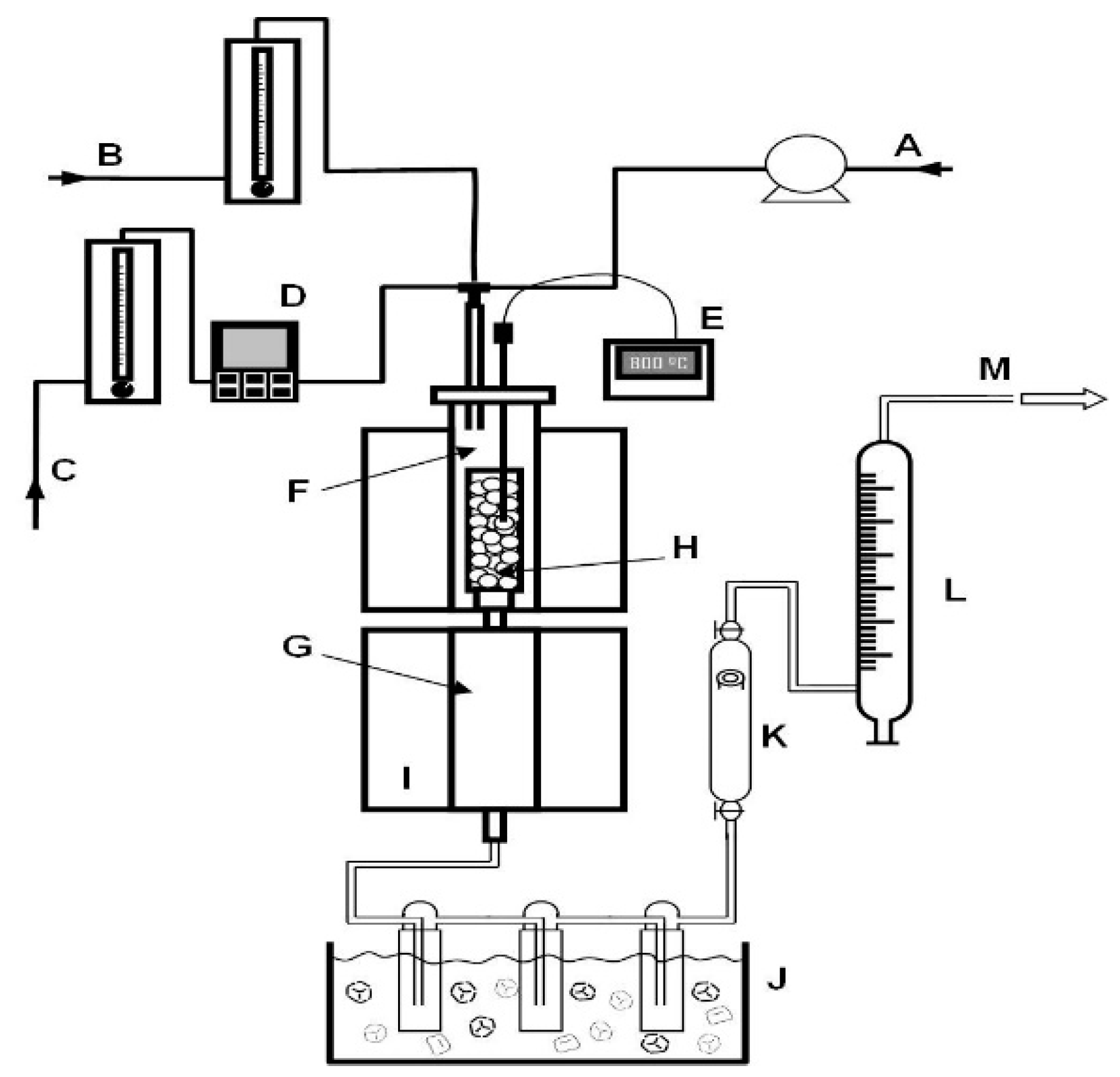
2.4. Catalyst Performance Testing

Glycerol steam reforming was performed in two continuous flow fixed-bed tubular stainless-steel reactors in series (ID = 5.2 cm; total length = 106 cm) (Figure 1). Catalysts were reduced in situ by H2/N2(50/50) flow at 700 °C for 2 h.
A glycerol–water mixture was injected with a HPLC pump (1.15 g·min−1), using a steam to carbon feed ratio of 5.7 (aqueous solution of glycerol 20% v/v). The steam to carbon feed ratio (S/C) is expressed as mol/mol. This ratio maximized gas conversion and H2yield in preliminary studies with our experimental set-up. In addition, this water/glycerol ratio has been frequently used [39,40]. Weight hourly space velocity (WHSV) was calculated as grams of glycerol·h−1 per gram of catalyst.
This variable was studied by changing the catalyst load in the reactor. Nitrogen was used as the carrier gas during the reaction and a nitrogen/glycerol molar ratio of 2.5 was maintained.Steam to carbon and nitrogen/glycerol molar ratio were established according to preliminary studies with this experimental set-up.
The composition of the produced syngas was determined by gas chromatography in a VARIAN 3900 chromatograph (Varian, Palo Alto, CA, USA), equipped with a TCD and automatic injector by air-actuated valve (Valco 2 positions). Carboxen-1000 60–80 mesh column of 4.5 m of length and 1/8” of diameter was employed. Argon was use as carrier gas.

2.5. Data Analysis

Glycerol conversion into gases was calculated based on Equation (4):
C o n v e r s i o n   =   C   m o l e s   i n   g a s   p r o d u c t s 3 * g l y c e r o l   m o l e s   i n   t h e   f e e d s t o c k
The distribution of products indicated as H2, CO, CO2, CH4, C2H4, and C2H6% was calculated as: produced moles of H2, CO, CO2, CH4, C2H4, and C2H6, respectively, divided by total moles of gas phase × 100.
The hydrogen production was indicated as H2/glycerol and it was calculated based on the following Equation (5):
H 2 g l y c . = H 2   m o l e s   i n   g a s   p r o d u c t s g l y c e r o l   m o l e s   i n   t h e   f e e d s t o c k
where 7 would be the maximum number of H2 moles that could be produced per glycerol mole, according to Equation (1).

3. Results and Discussion

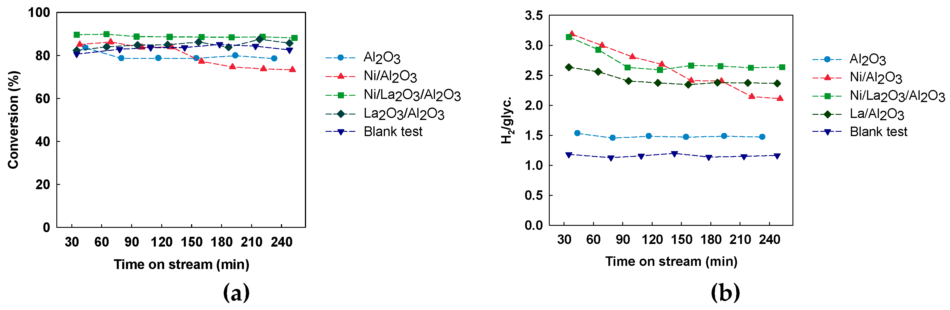
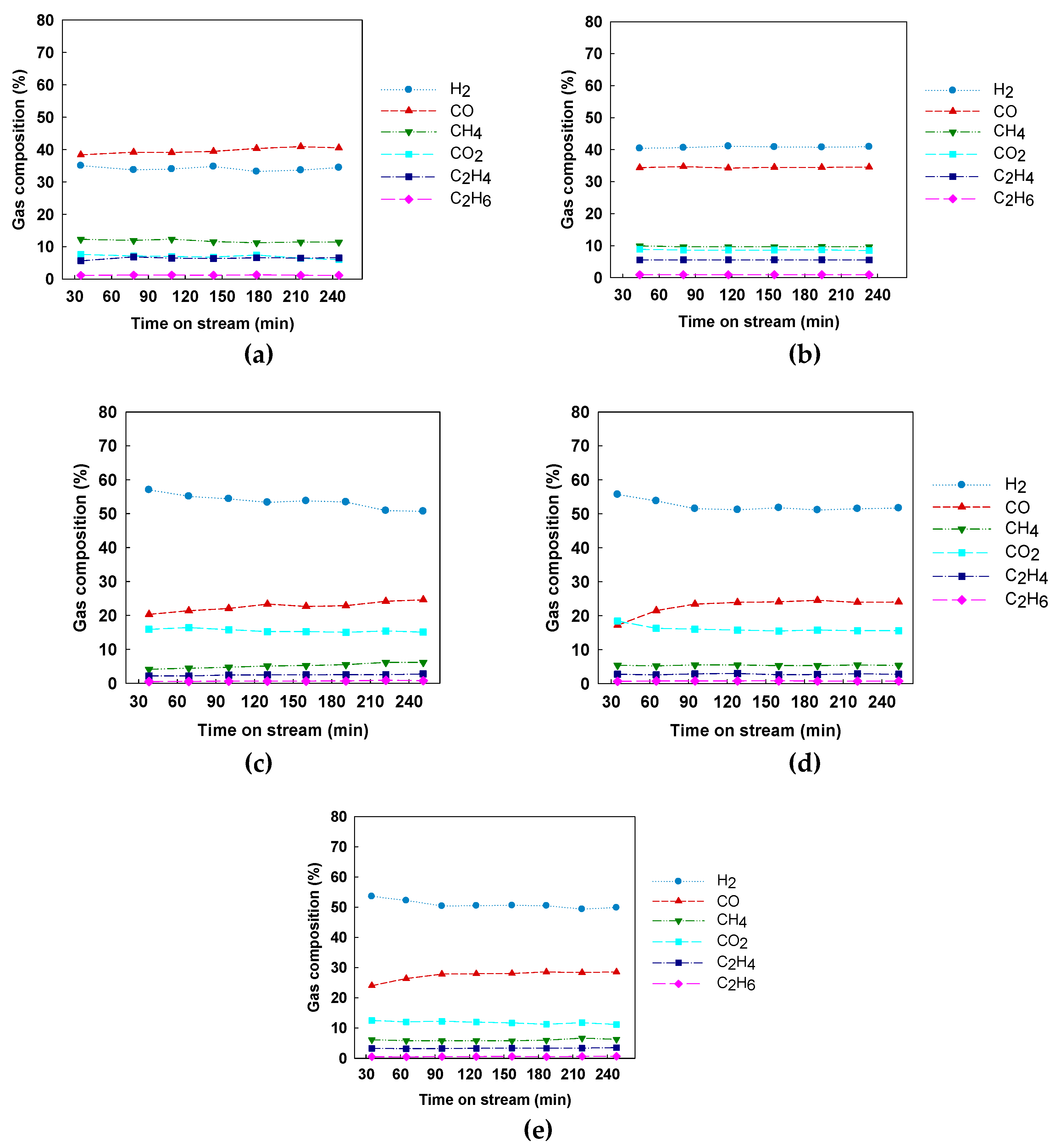
3.1. Catalytic Activity

Firstly, a blank test was performed to determine the thermal decomposition of the feed solution under the reaction conditions. During this run, the reactor was kept empty. In addition, a reaction only with the support (Al2O3) was carried out to distinguish the effect of temperature, the support and the catalyst. The activities of the support (Al2O3 rings), the modified support (La2O3/Al2O3) and the catalysts: Ni/Al2O3 and Ni/La2O3/Al2O3were compared. These species were tested at 600 and 700 °C. Similar trends were observed at both temperatures, but lower gas production was achieved at 600 °C; therefore, only the results at the highest temperature are shown in this report. As it can be seen in Figure 2, the presence of any of the catalyst improved glycerol conversion into gasesand hydrogen production regarding the results of the blank test or the test with Al2O3.
On the other hand, Ni/Al2O3 showed a noticeable deterioration in the gas production over time; whereas, Ni/La2O3/Al2O3kept acceptable results. The modified support was also active in glycerol steam reforming since the hydrogen production with this filling material was higher than the production achieved with Al2O3 and close to the catalysts with nickel.
Figure 3 shows the gas composition of the obtained gas for each reaction. In the blank test, Figure 3a, glycerol decomposition was mainly promoted while water–gas shift reaction showed low conversion since CO concentration was higher than H2 concentration. This state was inverted with Al2O3 as filling material (Figure 3b). However, the modification of the support or the impregnation of nickel was necessary to reach high H2 concentrations. These filling materials favored the global steam reforming reaction, that is, glycerol decomposition and water–gas shift reaction.
Nickel over Al2O3 is widely used in steam reforming; nevertheless, the acid–base property of the support influences catalyst reactivity and stability. As shown by other authors, acid supports, such as Al2O3, tend to dehydrate glycerol, which yields undesired coke precursors and can clog the system by subsequent condensation. When strong basic supports were used, the catalysts were also deactivated faster than with alumina [25]. Montini et al. [29] and Iriondo et al. [28] modified Pt/Al2O3 and Ni/Al2O3, respectively, with CeO2 and La2O3. The support’s acidity was adequately reduced by these promoters, and high catalyst activity was reached, with decrease of coke deposition.
As it can be seen in Figure 3e, La-modified Al2O3 showed high activity in steam reforming reaction, despite the lack of a metal commonly known as active phase in this process, such as Ni, Ir, Co, Pt, or Pd. The support La2O3/Al2O3 seemed to reduce support’s acidity and promote hydrogen production [9]. This effect, in addition to the reduction of the formation of coke precursors, led to an improvement on the stability of the catalyst Ni/La2O3/Al2O3. In contrast, the H2 production with this catalyst was slightly lower than the initial H2 production with Ni/Al2O3, as it can be seen in Figure 2.

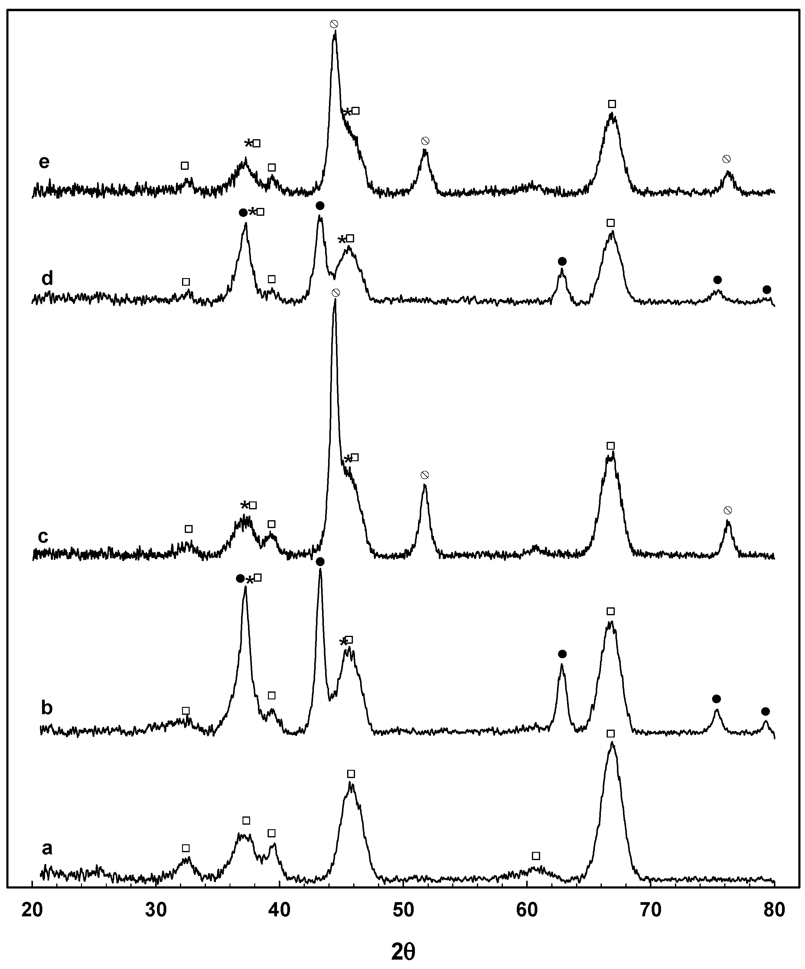
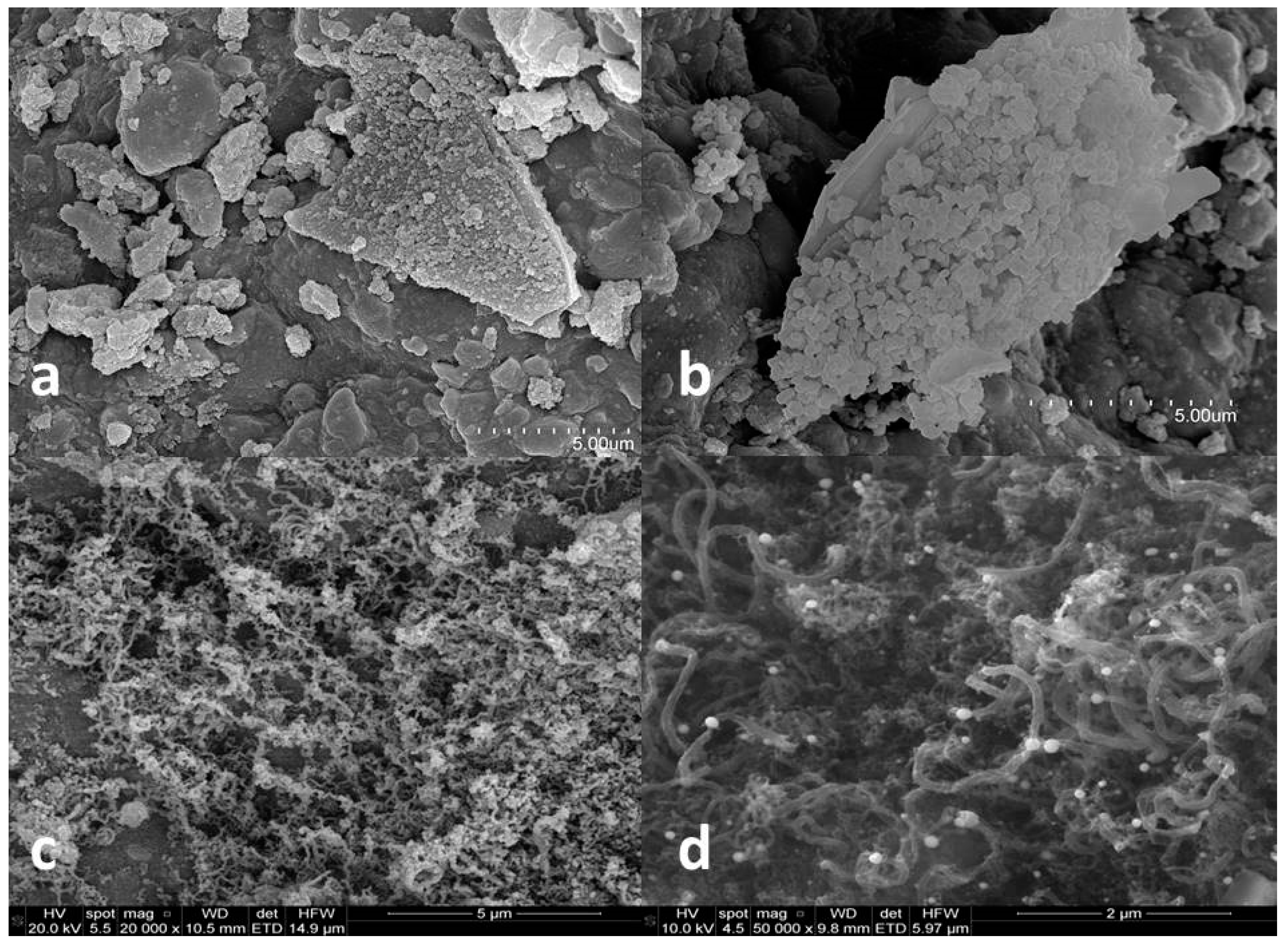
3.2. Catalyst Characterization

Fresh and used catalysts were characterized and the results are shown in the following tables and figures. Table 1 shows the specific surface areas of the catalysts and the support. The impregnation of nickel species into Al2O3 decreased this parameter in relation to the support. However, the modification of the support with La2O3 led to a catalyst with higher surface area, even greater than that of the support. According to some authors, lanthanum ions would form an atomic dispersed layer on alumina, which could favor the increase in surface area [26,35,36]. XRD patterns of the catalysts are shown in Figure 4.
The bare support pattern shows the characteristic peaks of γ-Al2O3 (JCPDS 86-1410). Regarding fresh catalysts, the most probable nickel species are NiO and NiAl2O4, as product of an efficient conversion of nickel nitrate into nickel oxide and the formation of a spinel phase between nickel oxide and alumina of the support. There is a number of diffraction peaks corresponding to crystalline phases of NiOat 2 = 43.3° (JCPDS 73-1523). In addition, there is a peak at 37.2°, that could characterize NiO, NiAl2O4 and γ-Al2O3 (JCPDS 73-1523, 78-1601, 86-1410). The predominant specie of nickel seems to be nickel oxide, and the presence of NiAl2O4 could not be ensured since its characteristic peaks are very close to γ-Al2O3 peaks (19.5°, 31.7°, 37.5°, 45.3°, 60.2°, 65.8°, JCPDS 78-1601). Diffraction peaks corresponding to lanthanum crystalline species were not detected.
According to other authors, it could be that lanthanum species would be embedded into the alumina porous lattice or, more probable, they were highly dispersed on surface, leading to undetectable small crystallites [26,28,35,37,38].Crystallite size of NiO was calculated for fresh catalysts by Scherrer equation. The peak with orientation in the (2 0 0) plane (2θ = 43.3°) was used for the calculation. The calculated crystallite size of NiO was 11.6 nm for Ni/Al2O3 and 8.8 nm for Ni/La2O3/Al2O3. The smallest crystallite size in conjunction with the highest surface area seemsindicatea higher dispersion of nickel species in the La-modified catalyst [38].
Chemical composition of the fresh catalyst surfaces were analyzed by XPS and surface atomic compositions are collected in Table 2. Nickel and lanthanum species showed metal/Al ratios higher than nominal(values in brackets in Table 2).
This fact seems indicate that most of the metal had been supported on the surface of Al2O3. Higher superficial metal/Al ratios could mean higher availability of active sites of the catalyst during the reaction. After the modification of the support with lanthanum oxide, the ratio La/Al was 0.03, higher than its nominal value 0.02; meanwhile, Ni/Al ratio decreased. Some authors explain this fact by the location of lanthanum species over NiO particles [28].
Finally, SEM micrographs of fresh catalysts (Figure 5a,b) showed some conglomeration among the particles which form some slabs with superficial crystalline structures especially in the case of Ni/Al2O3. On the other hand, small amorphous particles are observed in Ni/La2O3/Al2O3 micrograph, which could be related to the previous hypothesis where lanthanum species ions are though to form an atomic dispersed layer [35,41].
In relation to the used catalyst, both of them showed a decrease in the surface area (Table 1). During steam reforming, coke is usually formed over the catalyst leading to a decrease in the specific area of the catalyst and, in most of cases, being the main reason for the deactivation of the catalyst [42,43]. On the other hand, Figure 4 shows the XRD patterns of used catalysts; they exhibited new diffraction lines compared to the fresh one. The used catalysts were reduced before the reaction and the nickel oxide peaks do not seem to be present; otherwise, peaks related to metallic nickel phase are noticed (2θ= 44.4°, 51.8°, 76.4°, JCPDS 04-850). There are peaks at 2θ = 37.2° and 45.5° which could be related to γ-Al2O3 or NiAl2O4. The reduction of the last specie is more difficult than the oxidation of NiO [28]. Crystalline carbon peaks were not detected in any of the patterns.
According to the activity of the catalyst Ni/Al2O3, its SEM micrographic (Figure 5c)showed a surface covered in carbon filaments, which could have encapsulated the active phase and be responsible for catalyst deactivation [42]. A thermogravimetric analysis (TGA-MS) of the used catalysts was also carried out to determine the coke deposition over the catalyst. As shown in Table 1, coke deposition over used Ni/Al2O3 was almost twice as much as the deposition over Ni/La2O3/Al2O3. This effect is in line with previous results when La2O3 was used to modify Pt and Ni/Al2O3 [28,29]. According to previous works [42], the first steps of filamentous carbon growth seems to allow Ni particles could be supported on the carbon filaments and possibly they were able to keep its activity. However, with higher carbon amount, some carbon deposits could form encapsulating carbon, which could be responsible for catalyst deactivation. Figure 5c seem to show a catalyst surface with excessive amount of filamentous coke, while in Figure 5d some points seem to be still accessible. Similar phenomena was seen in SEM micrographs of catalysts used for methane catalytic decomposition [42,44].
These results seem to indicate that the presence of La2O3 could enhance the reforming of carbon precursors and reduce the formation of carbonaceous deposits. This reforming would be favor by the decreasing of acidity of the support due to the presence of La2O3[28,35]. The lowest carbon amount over the catalyst could reduce the loss of catalyst activity over the time.

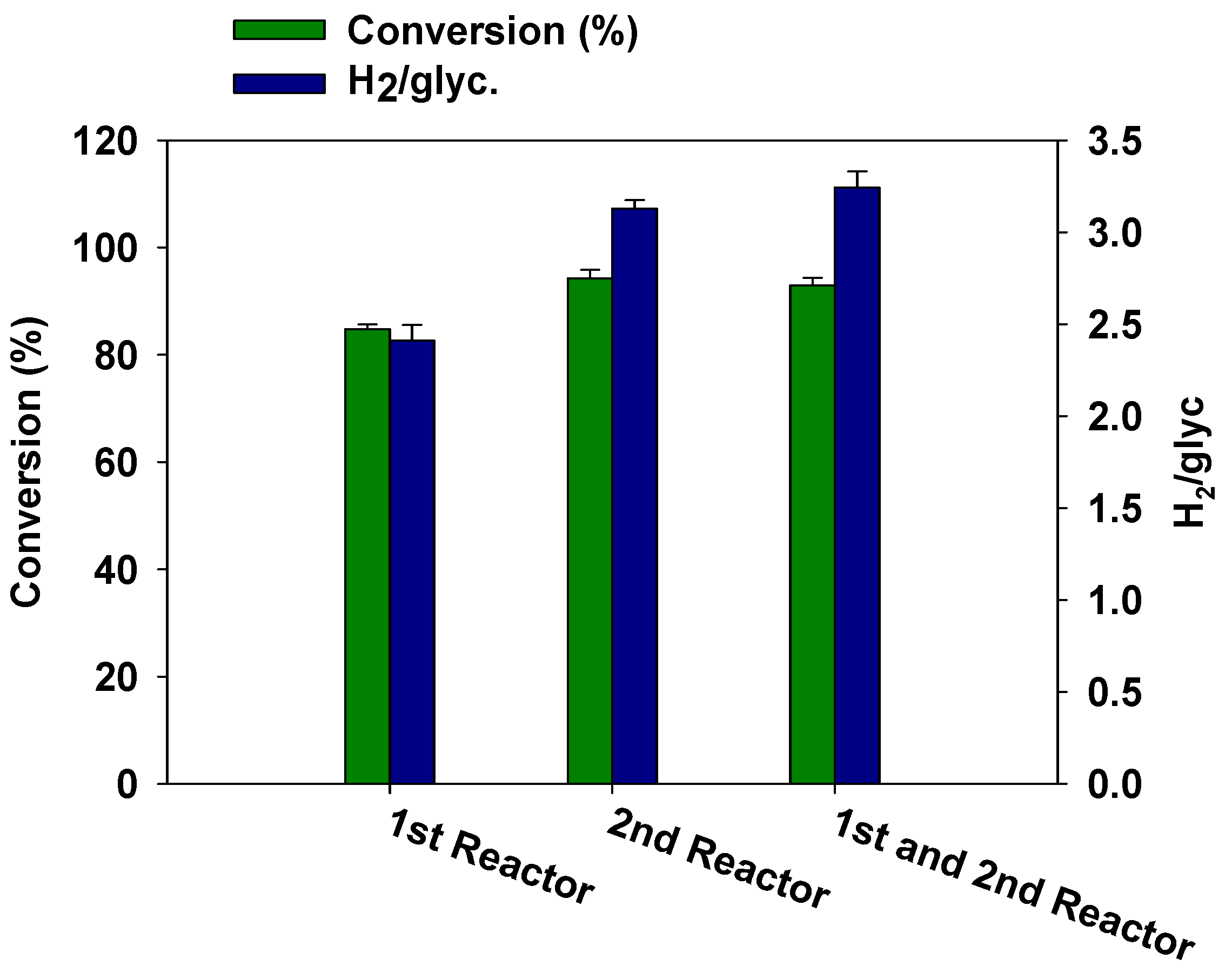
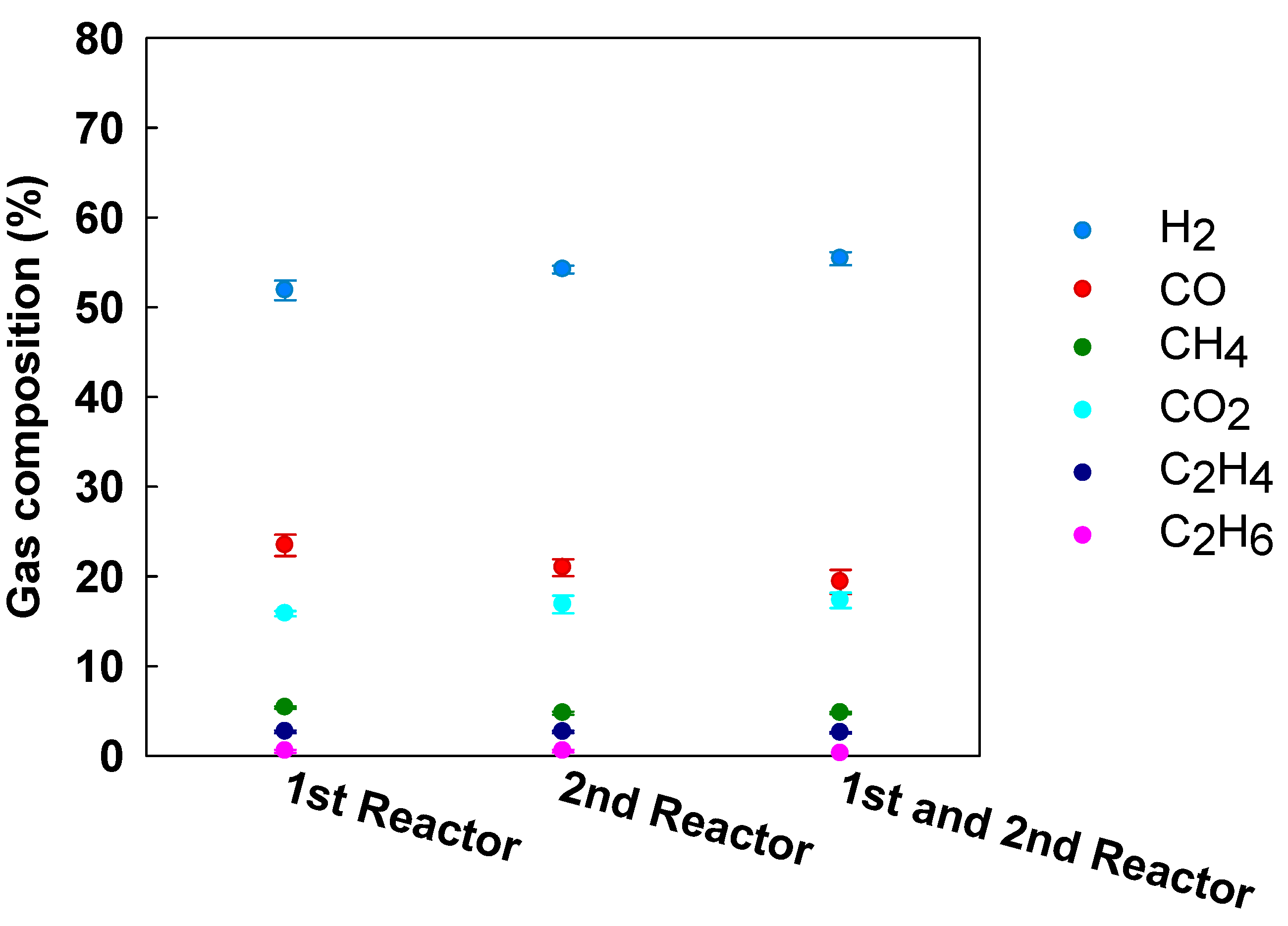
3.3. Effect of Catalyst Arrangement

The experimental set-up had two reactors in series, so the effect of the catalyst distribution management was studied. This arrangement of the reactors could be designed for two serial phases: a reforming reactor plus a WGS reactor. However, in this work all the conditions were kept similar in both reactors except for the presence of the catalyst, to see if there would be differences in the reaction whether the contact between reagents and catalyst happen in the first reactor, the second or in both reactors. Firstly the whole amount of catalyst was placed in the first reactor, then in the second reactor and, finally, half amount of catalyst was placed in each reactor. As seen in Figure 6, the reaction was improved when there was some of catalyst in the second reactor. The highest hydrogen production was obtained when half amount of catalyst was placed in each reactor, although the results were close to the obtained ones when the whole amount of catalyst was in the second reactor.
In Figure 7, the composition of the gas produced in the reactions of this section was showed. When there was catalyst in both reactors hydrogen concentration was higher. In this case, carbon monoxide and hydrocarbon production was lower than in previous reactions. On the other hand, carbon monoxide production was promoted against carbon dioxide production over time, which could be due to catalyst deactivation [45].
When the catalyst is placed in the second reactor, it is expected that the feed mixture makes contact with the catalyst in a more dissociated form than when the catalyst is located in the first reactor. The compounds which have to be converted in light gases will show smaller molecular weight. According to previous works, the hydrocarbon activation requires more than one atom of the active metal and the higher hydrocarbon size, the greater thenumber of atoms is required. Then, catalytic properties of an amount of solid were higher with smaller hydrocarbons [46,47]. On the other hand, the presence of catalyst in both reactors showed a synergistic effect which partially improves the global results. In this way, the use of two catalytic beds could be considered for longer reactors or higher scale.

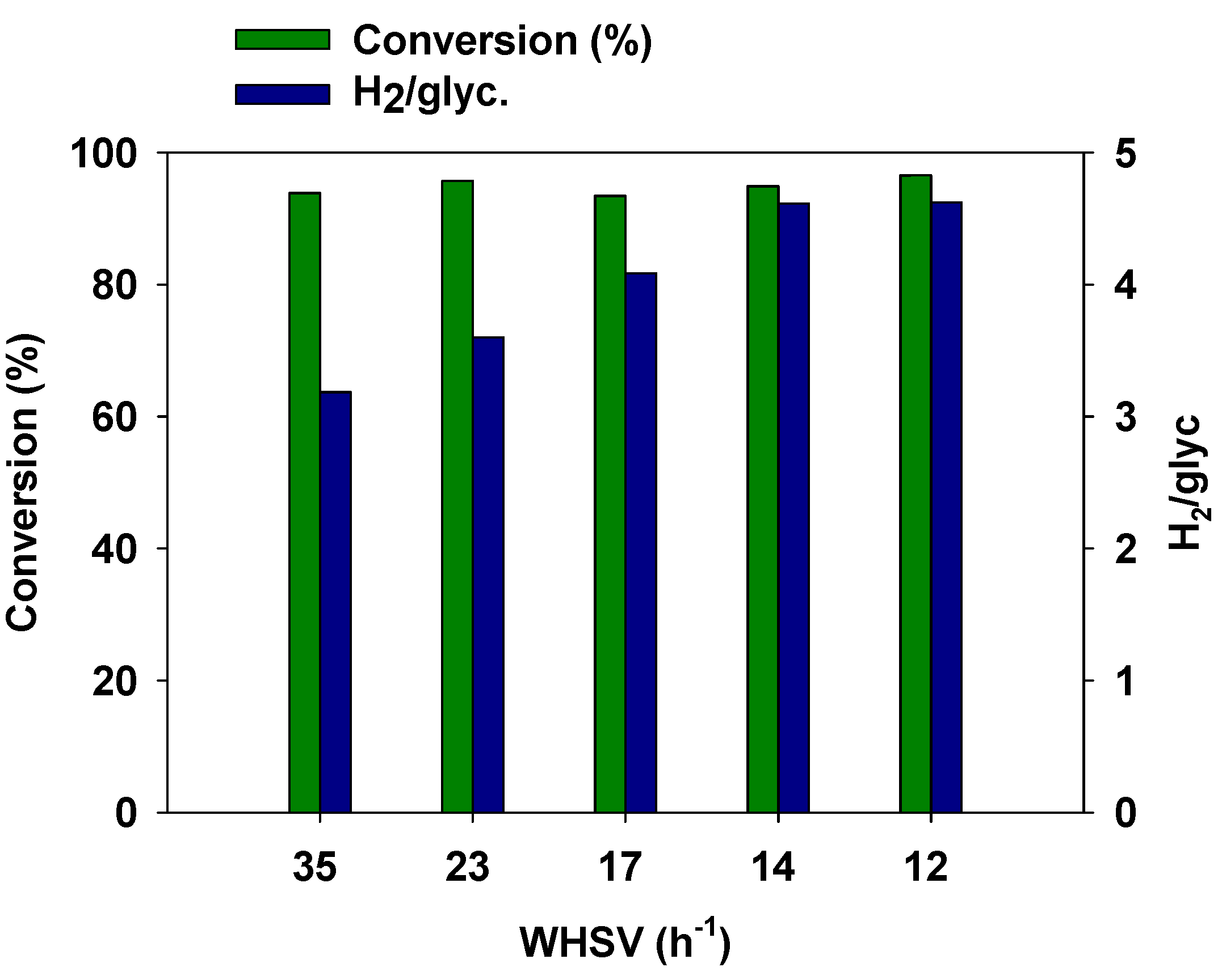
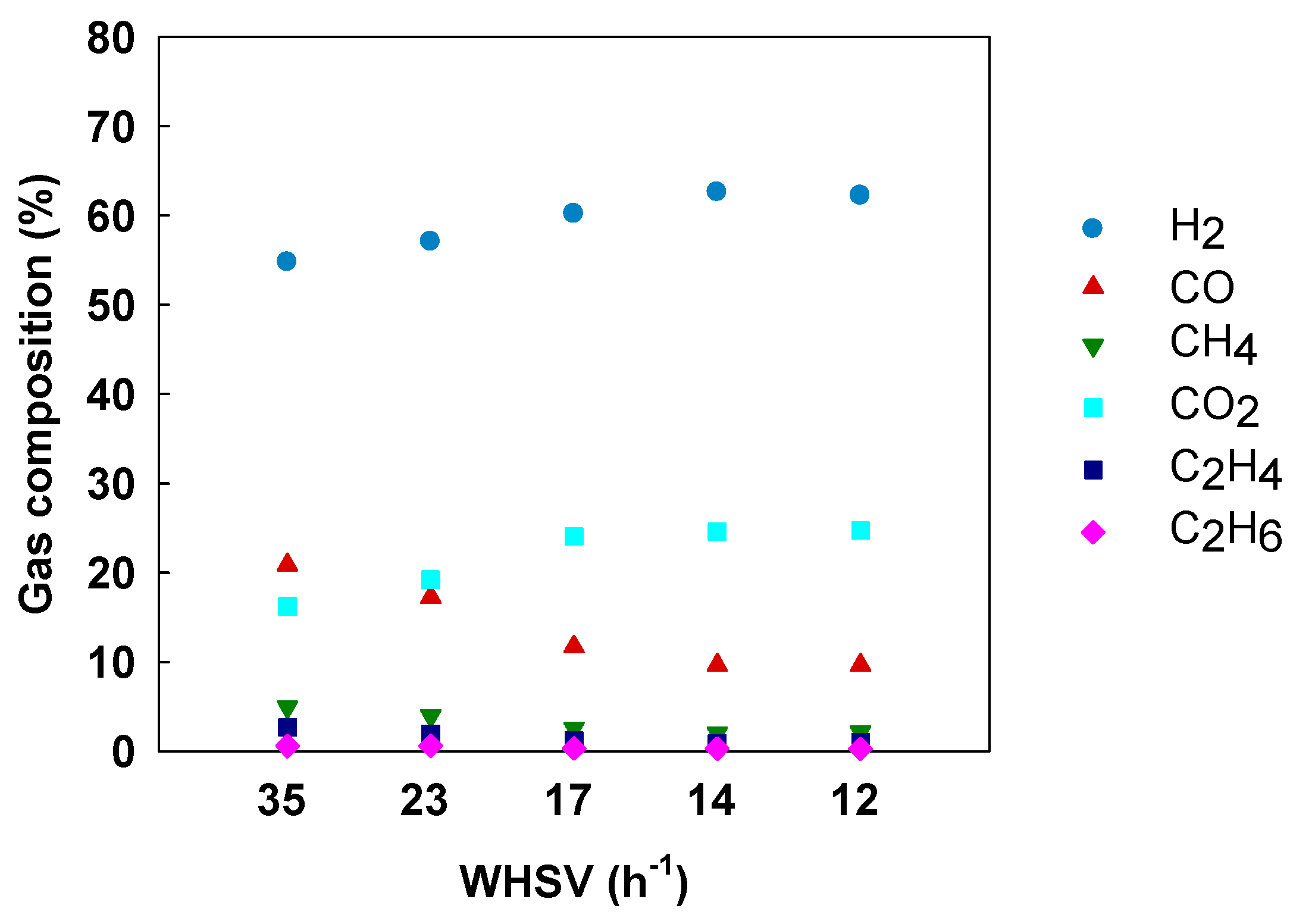
3.4. Effect of Space Velocity

The effect of WHSV was also studied; the results are shown in Figure 8 and Figure 9. The catalyst load in the reactors was increased to reduce the WHSV. Glycerol conversion into gaseswas the same for every space velocity; nevertheless, the hydrogen production was promoted by the decrease of this variable. Higher catalyst loads enhanced hydrogen and carbon dioxide selectivity at the expense of carbon monoxide and hydrocarbon concentrations. The variation of WHSV in previous works led to similar results [23,48,49]. The decrease in the residence time of reactants reduced the availability of the active sites, decreasing glycerol steam reforming progress. In the same way, when feedstock flow rate was decreased or the load of the active phase was increased, similar results would be obtained [12,50].
The decrease in the space velocity also enhanced the WGS reaction, since carbon monoxide concentration decreased to 14 h−1 as WHSV.The results with 14 h−1 and 12 h−1 as space velocity were similar; for these reactions, the amount of catalyst was 5 and 6 g, respectively. Therefore, 5 g as catalyst load was enough to reach the best results.

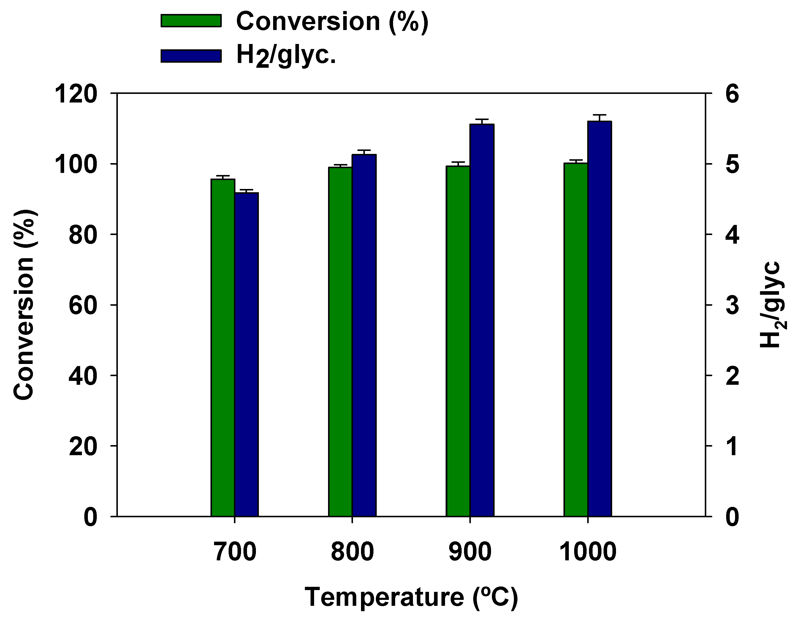
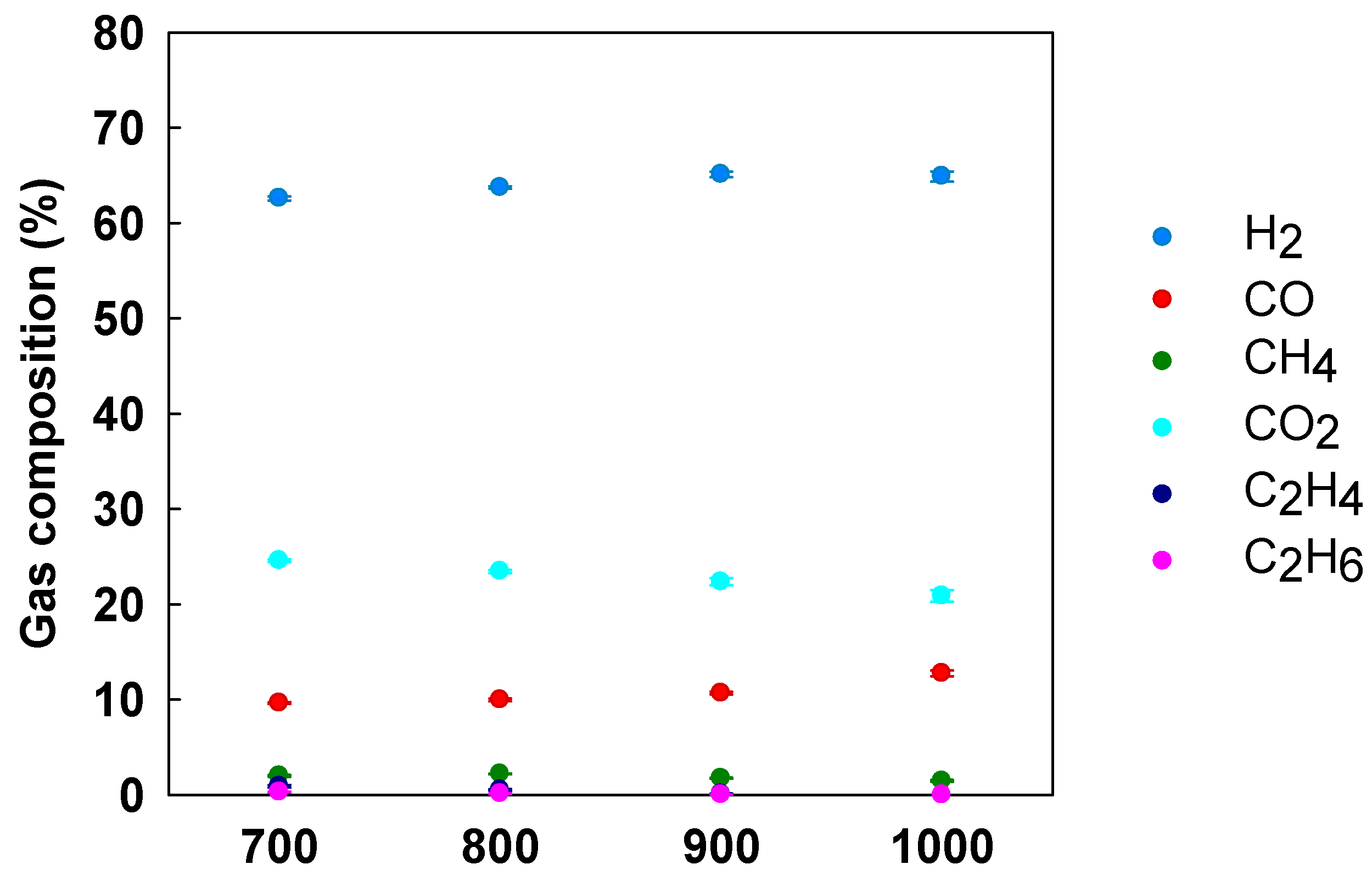
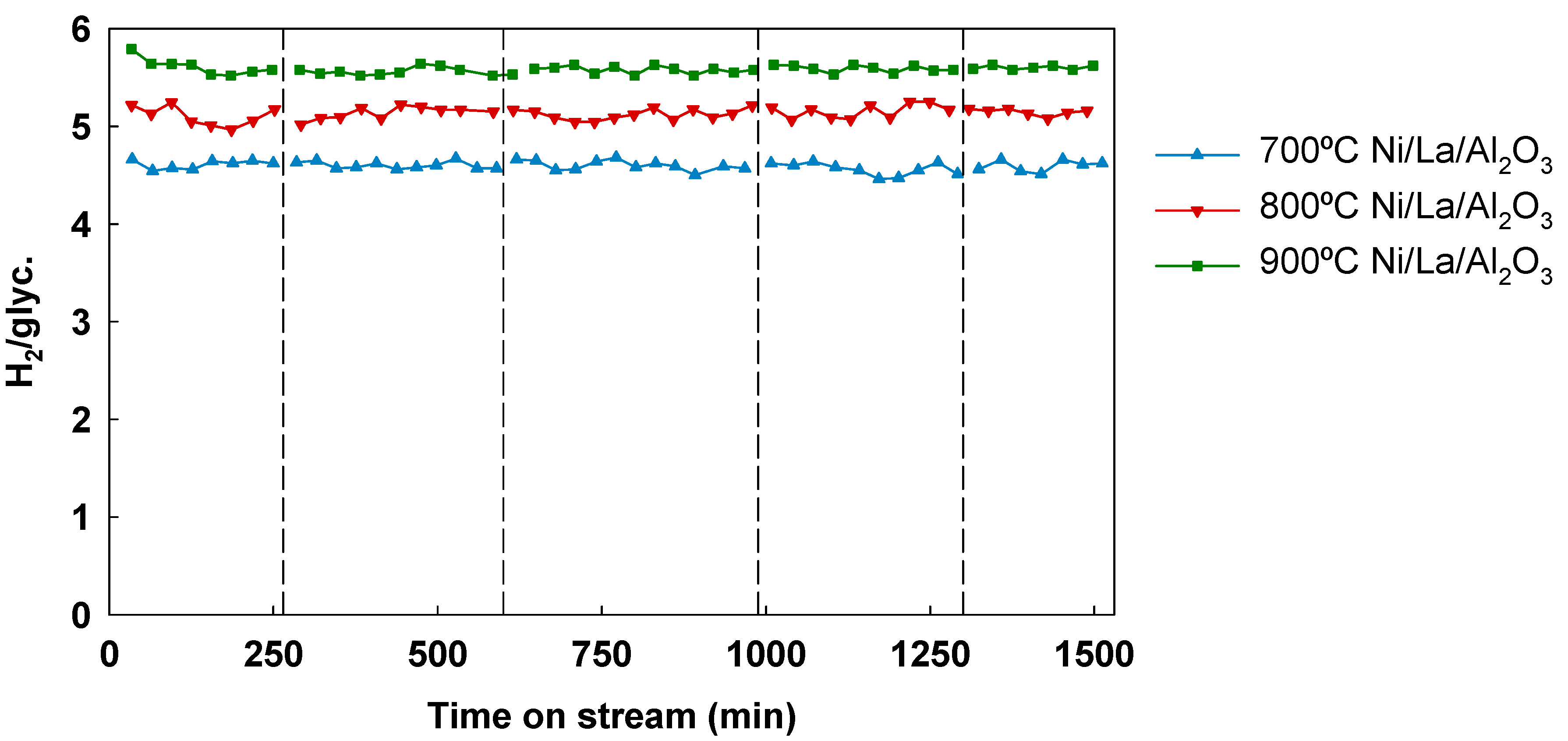
3.5. Effect of Temperature

The last studied operational condition was the reaction temperature. Glycerol steam reforming was carried out at 700, 800, 900, and 1000 °C, whose results are shown in Figure 10 and Figure 11. From thermodynamic considerations, glycerol conversion into gases would be limited at low temperatures due to the fact that steam reforming is an endothermic reaction.
When temperature was increased, glycerol conversion into gases and hydrogen production also increased. Glycerol complete conversion into gas was reached at 900 and 1000 °C and the hydrogen production reached a H2/glycerol mole ratio of 5.6.
These results cannot be directly related to the effect of the catalyst because under these conditions temperature had the strongest effect. Similar results could be obtained without catalyst if the steam reforming were carried out at 900–1000 °C. On the other hand, the greatest catalyst effectwasobserved at 700 °C. At this temperature, a reaction without catalyst was previously performed and the glycerol conversion into gaseswas close to 80% and 1.5 mole of H2 were produced per mole of glycerol. On the other hand, with catalyst, 95% of glycerol conversion into gases and a H2/glycerol molar ratio of 4.6 were obtained.These results would improve glycerol conversion into gases obtained in previous works with Ni-catalysts [51].
Although glycerol decomposition is favored with temperature, water–gas shift and methanation reactions are favored at low temperatures. H2 and CO2 production was promoted at high temperatures, whereas the highest CO and hydrocarbons concentrations were obtained at low temperatures (Figure 11). Gas composition at 700 °C was kept along the time; the average values were: 62.5% H2, 24.4% CO2, 9.7% CO, 2.1% CH4, 1.0% C2H4, and 0.3% C2H6. Consequently, high hydrogen and low hydrocarbon concentrations were obtained under these conditions.
Catalyst was subjected to five consecutive reaction cycles, to know if the catalyst Ni/La2O3/Al2O3 suffered fast deactivation. The catalyst was not treated in order to remove coke before H2reduction.The cycles were carried out at 700, 800, and 900 °C and the results are showed in Figure 12, where the cycles are separated by discontinuous vertical lines. After each cycle, the particles of nickel which could have been oxidized by the contact with the steam were reduced at 700 °C with a flow of H2/N2 (50%). As it can be observed in the figure, the activity of the catalyst was maintained at least for 1500 min of reaction.
Hydrogen production is usually the parameter more affected by catalyst deactivation. For this reason, this parameter was chosen to study the deactivation of the catalyst. On the other hand, the rest of parameters, such as glycerol conversion into gases and gas composition, were constant over the time. La-modification of the support led to a highly stable catalyst, with better catalytic performance than bare Ni/Al2O3 catalyst [52].
The catalytic stability was comparable to new catalysts, such as Ni/Nb2O5/Al2O3 [38]. When catalyst regeneration is necessary at larger scale, two alternative strategies were proposed by Montero et al. [53]. The use of several fixed bed reactors (one in reduction step and the others in reaction step) or a fluidized bed reactor with catalyst circulation. In our case, calcination seems to be not necessary, so the process becomes easier.

3.6. Energy Use of the Product

The main aim of this work was the production of hydrogen-rich syngas; however, the gas produced in steam reforming plants is frequently employed as an energetic stream. In these cases, the lower heating value of the gas is crucial to determine the efficiency of the plant.
In Table 3, the energy production of the gas stream was evaluated as energy per unit mass of glycerol from the feedstock. The contact time for calculation was 180 min and the lower heating value and the flow of the gas per kg of glycerolwere considered.
As seen in Table 3, the stream with the lowest energy capacity was the obtained when Ni/Al2O3 was used. This catalyst showed signs of deactivation under these conditions (Figure 2 and Figure 3). Carbon monoxide and hydrocarbon contents were higher in blank test and with Al2O3.
These species strongly affected the energy capacity of the produced stream. For this reason, blank and Al2O3 tests showed higher energy production than Ni/Al2O3 test. On the other hand, the presence of the rest of catalysts led to higher gas production and high hydrogen concentration, both facts increased the energy capacity of the products, as seen in Table 3.
Finally, the operating conditions were also important in energy production. The decrease in the space velocity, by increasing catalyst load, produced a more energetic stream. Therefore, the optimization of the catalyst is necessary in this process, as well as the optimization of the operational conditions.

4. Conclusions

The use of Ni/Al2O3, Ni/La2O3/Al2O3, or La2O3/Al2O3 as catalysts in glycerol steam reforming prompted high glycerol conversion into gas with important hydrogen production. Among them, Ni/La2O3/Al2O3 showed the best stability over the reaction time. La-modified support led to higher surface area and lower coke deposition after the reaction. The ability of the lanthanum species to promote the reforming of the carbon precursors allowed an improvement of the results.
The use of part of the catalyst in the second reactor of the experimental set-up significantly improved the hydrogen production. In addition, the process was improved by the decrease in WHSV, increasing the catalyst load. Complete glycerol conversion into gas was obtained at higher temperatures, but the most significant effect of the catalyst was observed at 700 °C.
Under the optimal conditions, the catalyst was reused and, after five cycles, deactivation signs were not detected. The maximum energy capacity of the produced gas per kg of glycerol took place when Ni/La2O3/Al2O3 was used under the optimal operating conditions.

Author Contributions

Conceptualization, J.M.E. and N.S.; methodology, J.M.E. and N.S.; validation, J.M.E., N.S., and S.N.; formal analysis, N.S.; investigation, N.S.; resources, J.M.E. and J.F.G.; data curation, N.S., and S.N.; writing—original draft preparation, N.S.; writing—review and editing, N.S. and S.N.; visualization, J.M.E., S.N. and J.F.G.; supervision, J.M.E. and J.F.G.; project administration, J.M.E.; funding acquisition, J.M.E. and J.F.G.

Funding

This research was funded by the Junta de Extremadura and FEDER, grant number GR18150.

Acknowledgments

The authors are grateful to the Junta de Extremadura and FEDER (Fondo Europeo de Desarrollo Regional “Una manera de hacer Europa”) for the financial help by project GR18150. Authors acknowledge the SAIUEX service of the University of Extremadura for catalyst characterization, especially D. Gamarra for its technical assistance. Also, authors thank Saint-Gobain NorPro for donating the support of the catalyst. Nuria Sánchez would like to acknowledge the Ministry of Education from Spain for the FPU grant received.

Conflicts of Interest

The authors declare no conflict of interest.

References

  1. Rodríguez-Fernández, J.; Hernández, J.J.; Calle-Asensio, A.; Ramos, A.; Barba, J. Selection of blends of diesel fuel and advanced biofuels based on their physical and thermochemical properties. Energies 2019, 12, 2034. [Google Scholar] [CrossRef]
  2. White, R.; Navarro-Pineda, F.S.; Cockerill, T.; Dupont, V.; Sacramento Rivero, J.C. Direct methanation of glycerol to bio-synthetic natural gas at a biodiesel refinery. Energies 2019, 12, 678. [Google Scholar] [CrossRef]
  3. Avasthi, K.S.; Reddy, R.N.; Patel, S. Challenges in the production of hydrogen from glycerol—A biodiesel byproduct via steam reforming process. Procedia Eng. 2013, 51, 423–429. [Google Scholar] [CrossRef]
  4. Ayoub, M.; Abdullah, A.Z. Critical review on the current scenario and significance of crude glycerol resulting from biodiesel industry towards more sustainable renewable energy industry. Renew. Sustain. Energy Rev. 2012, 16, 2671–2686. [Google Scholar] [CrossRef]
  5. Leoneti, A.B.; Aragão-Leoneti, V.; de Oliveira, S.V.W.B. Glycerol as a by-product of biodiesel production in Brazil: Alternatives for the use of unrefined glycerol. Renew. Energ. 2012, 45, 138–145. [Google Scholar] [CrossRef]
  6. Susmozas, A.; Iribarren, D.; Dufour, J. Assessing the life-cycle performance of hydrogen production via biofuel reforming in Europe. Resources 2015, 4, 398–411. [Google Scholar] [CrossRef]
  7. Charisiou, N.; Siakavelas, G.I.; Dou, B.; Sebastian, V.; Hinder, S.; Baker, M.A.; Polychronopoulou, K.; Goula, M. Nickel supported on AlCeO3 as a highly selective and stable catalyst for hydrogen production via de glycerol steam reforming reaction. Catalysts 2019, 9, 411. [Google Scholar] [CrossRef]
  8. Liu, Y.; Guo, X.; Rempel, G.L.; Ng, F.T.T. The promoting effect of Ni on glycerol hydrogenolysis to 1,2-propanediol with in situ hydrogen from methanol steam reforming using a Cu/ZnO/Al2O3 catalyst. Catalyst 2019, 9, 412. [Google Scholar] [CrossRef]
  9. Lin, Y.C. Catalytic valorization of glycerol to hydrogen and syngas. Int. J. Hydrogen Energy 2013, 38, 2678–2700. [Google Scholar] [CrossRef]
  10. Ni, M.; Leung, D.Y.C.; Leung, M.K.H.; Sumathy, K. An overview of hydrogen production from biomass. Fuel Process Technol. 2006, 87, 461–472. [Google Scholar] [CrossRef]
  11. Adhikari, S.; Fernando, S.D.; Haryanto, A. Hydrogen production from glycerol: An update. Energy Convers. Manag. 2009, 50, 2600–2604. [Google Scholar] [CrossRef]
  12. Shao, S.; Shi, A.-W.; Liu, C.-L.; Yang, R.-Z.; Dong, W.-S. Hydrogen production from steam reforming of glycerol over Ni/CeZrO catalysts. Fuel Process Technol. 2014, 125, 1–7. [Google Scholar] [CrossRef]
  13. Sánchez, N.; Encinar, J.M.; González, J.F. Sorption enhanced steam reforming of glycerol: Use of La-modified Ni/Al2O3 as catalyst. Ind. Eng. Chem. Res. 2016, 55, 3736–3741. [Google Scholar] [CrossRef]
  14. Hashaikeh, R.; Butler, I.S.; Kozinski, J.A. Selective promotion of catalytic reactions during biomass gasification to hydrogen. Energy Fuel 2006, 20, 2743–2747. [Google Scholar] [CrossRef]
  15. Dauenhauer, P.J.; Salge, J.R.; Schmidt, L.D. Renewable hydrogen by autothermal steam reforming of volatile carbohydrates. J. Catal. 2006, 244, 238–247. [Google Scholar] [CrossRef]
  16. Cortright, R.D.; Davda, R.R.; Dumesic, J.A. Hydrogen from catalytic reforming of biomass-derived hydrocarbons in liquid water. Nature 2002, 418, 964–967. [Google Scholar] [CrossRef]
  17. Barati, M.; Babatabar, M.; Tavasoli, A.; Dalai, A.K.; Das, U. Hydrogen production via supercritical water gasification of bagasse using unpromoted and zinc promoted Ru/γ-Al2O3nanocatalysts. Fuel Process Technol. 2014, 123, 140–148. [Google Scholar] [CrossRef]
  18. Byrd, A.J.; Pant, K.K.; Gupta, R.B. Hydrogen production from glycerol by reforming in supercritical water over Ru/Al2O3 catalyst. Fuel 2008, 87, 2956–2960. [Google Scholar] [CrossRef]
  19. Adhikari, S.; Fernando, S.; Haryanto, A. Production of hydrogen by steam reforming of glycerin over alumina-supported metal catalysts. Catal. Today 2007, 129, 355–364. [Google Scholar] [CrossRef]
  20. Barbarias, I.; Artetxe, M.; Lopez, G.; Arregi, A.; Santamaria, L.; Bilbao, J.; Olazar, M. Catalyst performance in the HDPE pyrolysis-reforming under reaction-regeneration cycles. Catalysts 2019, 9, 414. [Google Scholar] [CrossRef]
  21. Calles, J.A.; Carrero, A.; Vizcaíno, A.J.; García-Moreno, L. Hydrogen production by glycerol steam reforming over SBA-15-supported nickel catalysts: Effect of alkaline earth promoters on activity and stability. Catal. Today 2014, 227, 198–206. [Google Scholar] [CrossRef]
  22. Iriondo, A.; Barrio, V.L.; Cambra, J.F.; Arias, P.L.; Güemez, M.B.; Navarro, R.M.; Sánchez-Sánchez, M.C.; Fierro, J.L.G. Influence of La2O3 modified support and Ni and Pt active phases on glycerol steam reforming to produce hydrogen. Catal. Commun. 2009, 10, 1275–1278. [Google Scholar] [CrossRef]
  23. Pompeo, F.; Santori, G.F.; Nichio, N.N. Hydrogen production by glycerol steam reforming with Pt/SiO2 and Ni/SiO2 catalysts. Catal. Today 2011, 172, 183–188. [Google Scholar] [CrossRef]
  24. Zhang, B.; Tang, X.; Li, Y.; Xu, Y.; Shen, W. Hydrogen production from steam reforming of ethanol and glycerol over ceria-supported metal catalysts. Int. J. Hydrogen Energy 2007, 32, 2367–2373. [Google Scholar] [CrossRef]
  25. Pompeo, F.; Santori, G.; Nichio, N.N. Hydrogen and/or syngas from steam reforming of glycerol. Study of platinum catalysts. Int. J. Hydrogen Energy 2010, 35, 8912–8920. [Google Scholar] [CrossRef]
  26. Valliyappan, T.; Ferdous, D.; Bakhshi, N.N.; Dalai, A.K. Production of hydrogen and syngas via steam gasification of glycerol in a fixed-bed reactor. Top Catal. 2008, 49, 59–67. [Google Scholar] [CrossRef]
  27. Soares, R.R.; Simonetti, D.A.; Dumesic, J.A. Glycerol as a Source for Fuels and Chemicals by Low-Temperature Catalytic Processing. Angew. Chem. Int. Ed. 2006, 45, 3982–3985. [Google Scholar] [CrossRef]
  28. Iriondo, A.; Barrio, V.L.; Cambra, J.F.; Arias, P.L.; Güemez, M.B.; Navarro, R.M.; Sánchez-Sánchez, M.D.; Fierro, J.L.G. Hydrogen production from glycerol over nickel catalysts supported on Al2O3 modified by Mg, Zr, Ce or La. Top Catal. 2008, 49, 46–58. [Google Scholar] [CrossRef]
  29. Montini, T.; Singh, R.; Das, P.; Lorenzut, B.; Bertero, N.; Riello, P.; Benedetti, A.; Giambastiani, G.; Bianchini, C.; Zinoviev, S.; et al. Renewable H2 from glycerol steam reforming: Effect of La2O3 and CeO2 addition to Pt/Al2O3 catalysts. ChemSusChem 2010, 3, 619–628. [Google Scholar] [CrossRef]
  30. Montero, C.; Remiro, A.; Benito, P.L.; Bilbao, J.; Gayubo, A.G. Optimumoperatingconditions in ethanolsteamreformingover a Ni/La2O3-αAl2O3 catalyst in a fluidizedbed reactor. Fuel Process. Technol. 2018, 169, 207–216. [Google Scholar] [CrossRef]
  31. Carrero, A.; Vizcaíno, A.J.; Calles, J.A.; García-Moreno, L.J. Hydrogenproductionthroughglycerolsteamreformingusing Co catalystssupportedon SBA-15 dopedwith Zr, Ce and La. Energy Chem. 2017, 26, 42–48. [Google Scholar] [CrossRef]
  32. Pu, J.; Luo, Y.; Wang, N.; Bao, H.; Wang, X.; Qian, E.W. Ceria-promoted Ni-Al2O3 core-chell catalyst for steam reforming of acetic acid with enhanced activity and coke resistance. Int. J. Hydrogen Energy 2018, 43, 3142–3153. [Google Scholar] [CrossRef]
  33. Fatsikostas, A.N.; Verykios, X.E. Reaction network of steam reforming of ethanol over Ni-based catalysts. J. Catal. 2004, 225, 439–452. [Google Scholar] [CrossRef]
  34. Sánchez-Sánchez, M.C.; Navarro, R.M.; Fierro, J.L.G. Ethanol steam reforming over Ni/La–Al2O3 catalysts: Influence of lanthanum loading. Catal. Today 2007, 129, 336–345. [Google Scholar] [CrossRef]
  35. Valle, B.; Remiro, A.; Aguayo, A.T.; Bilbao, J.; Gayubo, A.G. Catalysts of Ni/α-Al2O3 and Ni/La2O3-αAl2O3 for hydrogen production by steam reforming of bio-oil aqueous fraction with pyrolytic lignin retention. Int. J. Hydrogen Energy 2013, 38, 1307–1318. [Google Scholar] [CrossRef]
  36. Mazumder, J.; de Lasa, H.I. Ni catalysts for steam gasification of biomass: Effect of La2O3 loading. Catal. Today 2014, 237, 100–110. [Google Scholar] [CrossRef]
  37. Boudjeloud, M.; Boulahouache, A.; Rabia, C.; Salhi, N. La-doped supported Ni catalysts for steam reforming of methane. Int. J. Hydrogen Energy 2019, 44, 9906–9913. [Google Scholar] [CrossRef]
  38. Menezes, J.P.S.Q.; Manfro, R.L.; Souza, M.M.V.M. Hydrogen production from glycerol steam reforming over nickel catalysts supported on alumina and niobia: Deactivation process, effect of reaction conditions and kinetic modeling. Int. J. Hydrogen Energy 2018, 43, 15064–15082. [Google Scholar] [CrossRef]
  39. Manfro, R.L.; Souza, M.M.V.M. Production of Renewable Hydrogen by Glycerol Steam Reforming Using Ni–Cu–Mg–Al Mixed Oxides Obtained from Hydrotalcite-like Compounds. Catal. Lett. 2014, 144, 867–877. [Google Scholar]
  40. Bettman, M.; Chase, R.E.; Otto, K.; Weber, W.H. Dispersion studies on the system La2O3γ-Al2O3. J. Catal. 1989, 117, 447–454. [Google Scholar] [CrossRef]
  41. Amin, A.M.; Croiset, E.; Epling, W. Review of methane catalytic cracking for hydrogen production. Int. J. Hydrogen Energy 2011, 36, 2904–2935. [Google Scholar] [CrossRef]
  42. Luo, N.-J.; Wang, J.-A.; Xiao, T.-C.; Cao, F.-H.; Fang, D.-Y. Influence of nitrogen on the catalytic behaviour of Pt/γ-Al2O3 catalyst in glycerol reforming process. Catal. Today 2011, 166, 123–128. [Google Scholar] [CrossRef]
  43. Takenaka, S.; Ogihara, H.; Yamanaka, I.; Otsuka, K. Decomposition of methane over supported-Ni catalysts: Effects of the supports on the catalytic lifetime. Appl. Catal. A Gen. 2001, 217, 101–110. [Google Scholar] [CrossRef]
  44. Sanchez, E.A.; Comelli, R.A. Hydrogen by glycerol steam reforming on a nickel–alumina catalyst: Deactivation processes and regeneration. Int. J. Hydrogen Energy 2012, 37, 14740–14746. [Google Scholar] [CrossRef]
  45. Khaodee, W.; Wongsakulphasatch, S.; Kiatkittipong, W.; Arpornwichanop, A.; Laosiripojana, N.; Assabumrungrat, S. Selection of appropriate primary fuel for hydrogen production for different fuel cell types: Comparison between decomposition and steam reforming. Int. J. Hydrogen Energy 2011, 36, 7696–7706. [Google Scholar] [CrossRef]
  46. Muraki, H.; Fujitani, Y. Steam reforming of n-heptane using a Rh/MgAl: I. Support and kinetics2O4 catalyst. Appl. Catal. 1989, 47, 75–84. [Google Scholar] [CrossRef]
  47. Sánchez, E.A.; D’Angelo, M.A.; Comelli, R.A. Hydrogen production from glycerol on Ni/Al2O3 catalyst. Int. J. Hydrogen Energy 2010, 35, 5902–5907. [Google Scholar] [CrossRef]
  48. Lee, S.Y.; Lim, H.; Woo, H.C. Catalytic activity and characterizations of Ni/K2TixOy–Al2O3 catalyst for steam methane reforming. Int. J. Hydrogen Energy 2014, 39, 17645–17655. [Google Scholar] [CrossRef]
  49. Bobadilla, L.F.; Blay, V.; Álvarez, A.; Domínguez, M.I.; Romero-Sarria, F.; Centeno, M.A.; Odriozola, J.A. Intensifying glycerol steam reforming on a monolith catalyst: A reaction kinetic model. Chem. Eng. J. 2016, 306, 933–941. [Google Scholar] [CrossRef]
  50. Salehi, E.; Azad, F.S.; Harding, T.; Abedi, J. Production of hydrogen by steam reforming of bio-oil over Ni/Al2O3 catalysts: Effect of addition of promoter and preparation procedure. Fuel Process Technol. 2011, 92, 2203–2210. [Google Scholar] [CrossRef]
  51. Zamzuri, N.H.; Mat, R.; Amin, N.A.S.; Telebian-Kiakalaieh, A. Hydrogen production from catalytic steam reforming of glycerol over various supported nickel catalysts. Int. J. Hydrogen Energy 2017, 42, 9087–9098. [Google Scholar] [CrossRef]
  52. Charisiou, N.D.; Papageridis, K.N.; Siakavelas, G.; Tzounis, L.; Kousi, K.; Baker, M.A.; Hinder, S.J.; Sebastian, V.; Polychronopoulou, K.; Goula, M.A. Glycerol steam reforming for hydrogen production over nickel supported on alumina, zirconia and silica catalysts. Top. Catal. 2017, 60, 1226–1250. [Google Scholar] [CrossRef]
  53. Montero, C.; Remiro, A.; Arandia, A.; Benito, P.L.; Bilbao, J.; Gayubo, A.G. Reproducible performance of a Ni/La2O3-aAl2O3 catalyst in ethanol steam reforming under reaction-regeneration cycles. Fuel Process Technol. 2016, 152, 215–222. [Google Scholar] [CrossRef]
Figure 1. Experimental set-up. A, B, C: Glycerol–water, H2 and N2 feeding system, respectively. D: Gas flowmeter. E: Temperature control system. F, G: 1st and 2nd reactor, respectively. H: Basket. I: Electronic furnace (heating system). J: Liquid sample collecting and condensation system. K: Gas sample collecting system. L: Total gas flowmeter (gas bubble flowmeter). M: Gas outlet.
Processes 07 00449 g001
Figure 2. (a)Glycerol conversion into gases and (b)H2/glycerol molar ratio over several catalysts (700 °C, 2 g of catalyst in the 1st reactor, no catalyst in the 2nd reactor, WHSV = 35 h−1).
Processes 07 00449 g002
Figure 3. Composition over several catalysts: (a) Blank test; (b) Al2O3; (c) Ni/Al2O3; (d) Ni/La2O3/Al2O3, and (e) La2O3/Al2O3 (700 °C, 2 g catalyst in 1st reactor, no catalyst in 2nd reactor, WHSV = 35 h−1).
Processes 07 00449 g003
Figure 4. Patternsof(a) Al2O3, (b) fresh Ni/Al2O3, (c) used Ni/Al2O3, (d) fresh Ni/La2O3/Al2O3, (e) used Ni/La2O3/Al2O3.(□ Al2O3, • NiO, * NiAl2O4 and ø Ni0).
Processes 07 00449 g004
Figure 5. Images of fresh and used catalyst: (a) Fresh Ni/Al2O3, (b) fresh Ni/La2O3/Al2O3, (c) used Ni/Al2O3, and (d) used Ni/La2O3/Al2O3.
Processes 07 00449 g005
Figure 6. Glycerol conversion into gases andH2/glycerol molar ratio with several catalyst arrangement (700 °C, 2 g Ni/La2O3/Al2O3 in total (WHSV = 35 h−1)).
Processes 07 00449 g006
Figure 7. Composition depending on the catalyst arrangement, (700 °C, 2 g Ni/La2O3/Al2O3 in total (weight hourly space velocity (WHSV) = 35 h−1)).
Processes 07 00449 g007
Figure 8. Conversion into gases and H2/glyc. molar ratio at selected WHSV, varying the catalyst load (700 °C, half amount of Ni/La2O3/Al2O3 in each reactor).
Processes 07 00449 g008
Figure 9. Composition at selected WHSV ratio, varying the catalyst load (700 °C, half amount of Ni/La2O3/Al2O3 in each reactor).
Processes 07 00449 g009
Figure 10. Glycerol conversion into gases and H2/glyc. molar ratio at selected reaction temperatures (2.5g of Ni/La2O3/Al2O3 in each reactor (WHSV = 14 h−1)).
Processes 07 00449 g010
Figure 11. Composition depending on temperature (2.5g of Ni/La2O3/Al2O3 in each reactor (WHSV = 14 h−1)).
Processes 07 00449 g011
Figure 12. Molar ratio at selected temperatures over several cycles of catalyst reutilization (2.5g of Ni/La2O3/Al2O3 in each reactor (WHSV = 14 h−1)).
Processes 07 00449 g012
Table 1. Area of fresh and used catalysts and carbonaceous deposits in used catalysts.
Al2O3Ni/Al2O3Ni/La2O3/Al2O3
FreshUsedFreshUsed
SBET (m2·g−1)159135123205140
Carbonaceous deposits (%) 4.81 2.49
Table 2. Surface atomic percentages and ratios of fresh catalysts.Theoretical ratios are shown in brackets.
Ni/Al2O3Ni/La2O3/Al2O3
Ni 2p9.947.35
La 3d5/20.96
Al 2s32.0635.38
O 1s50.0450.66
C 1s7.965.65
Ni/La/O/Al ratio0.31/0/1.56/1 0.21/0.03/1.43/1
(0.13/0/1.63/1)(0.13/0.02/1.66/1)
Table 3. Energy production of the gas per unit mass of glycerol. Reaction temperature: 700 °C.
Energy Production (MJ·kgglyc.−1)
Blank (WHSV = 35 h−1)14.48
Al2O3 (WHSV = 35 h−1)14.23
Ni/Al2O3 (WHSV = 35 h−1)13.06
Ni/La2O3/Al2O3 (WHSV = 35 h1)15.70
La2O3/Al2O3 (WHSV = 35 h−1)15.64
Ni/La2O3/Al2O3 (WHSV = 14 h1) 17.06

