Enhanced Lifetime Cathode for Alkaline Electrolysis Using Standard Commercial Titanium Nitride Coatings


Abstract
:1. Introduction
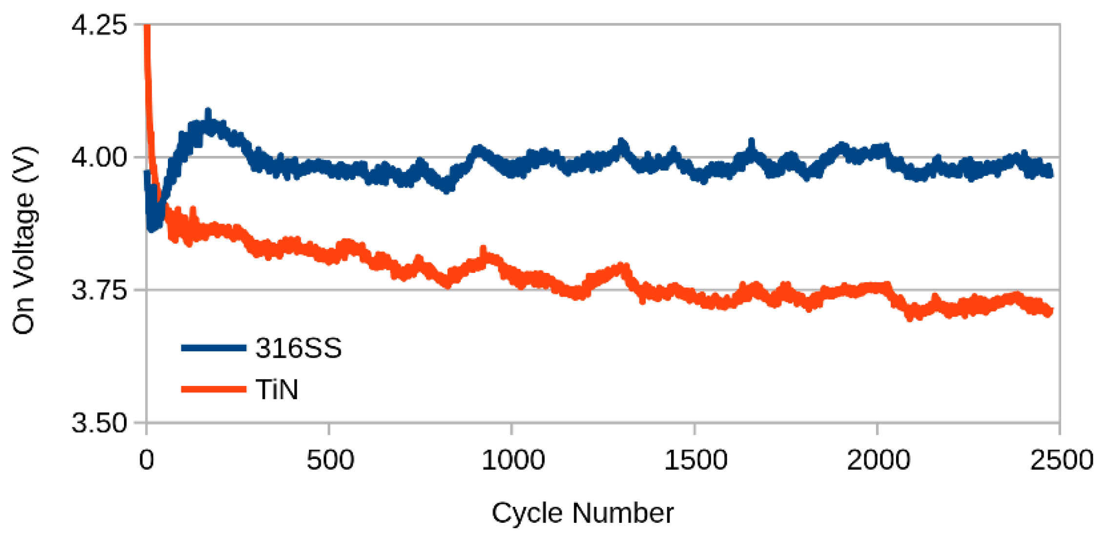
Accelerated Ageing
2. Materials and Methods
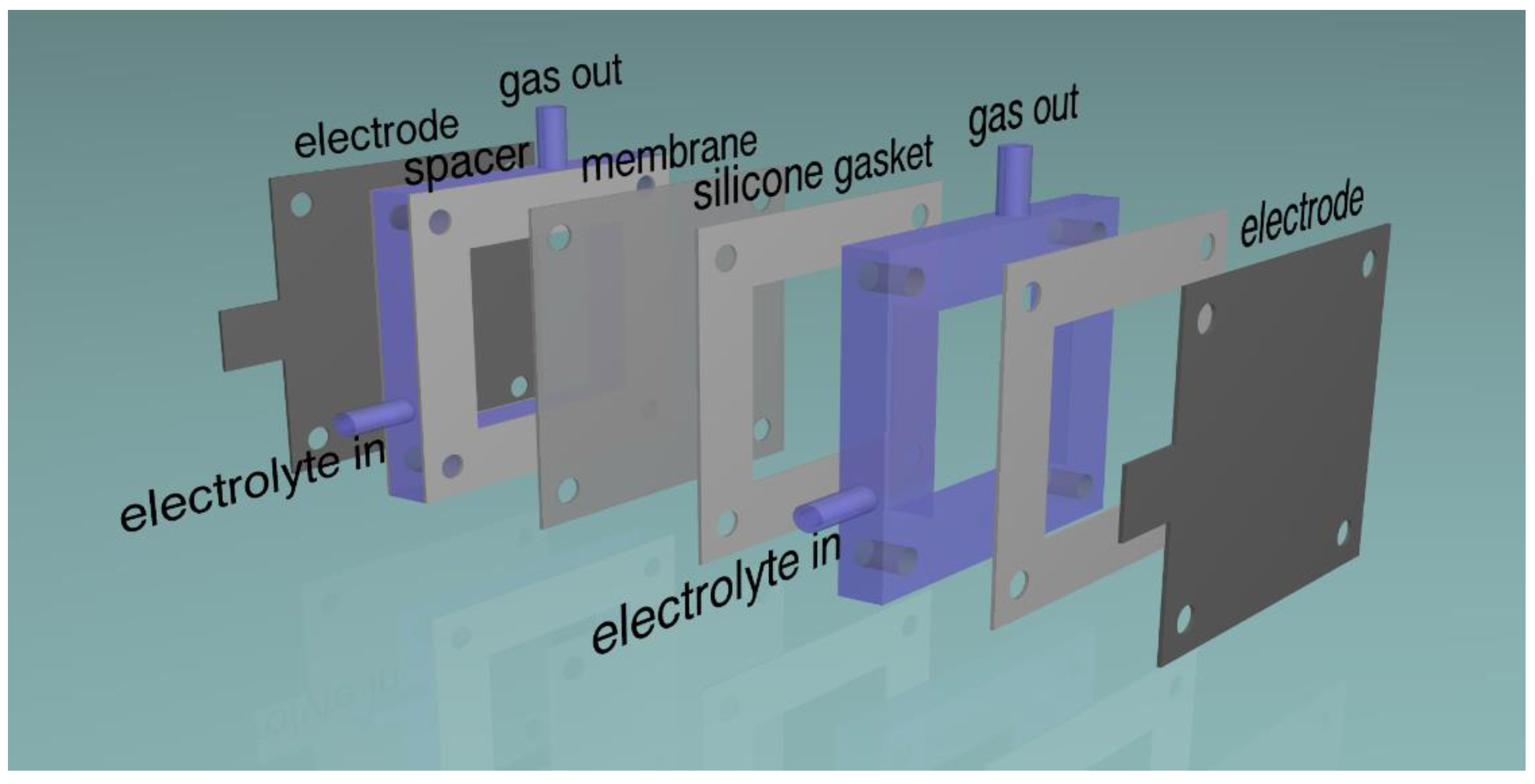
2.1. Electrodes
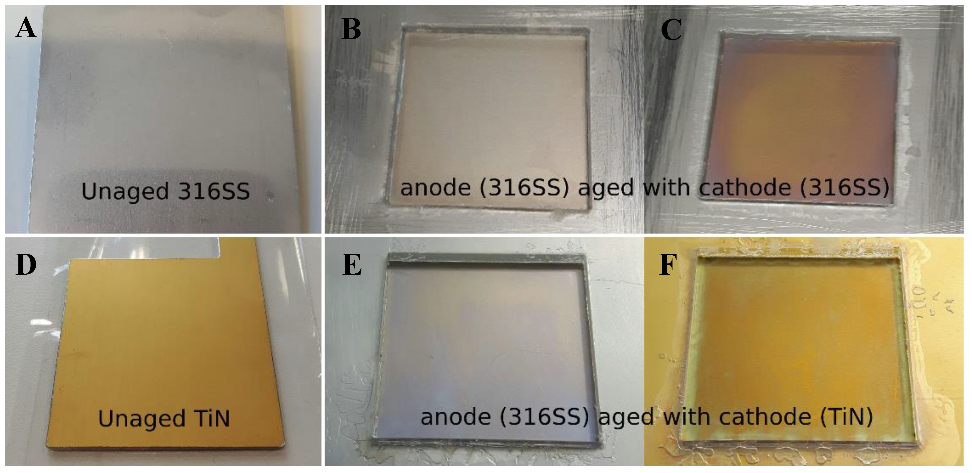
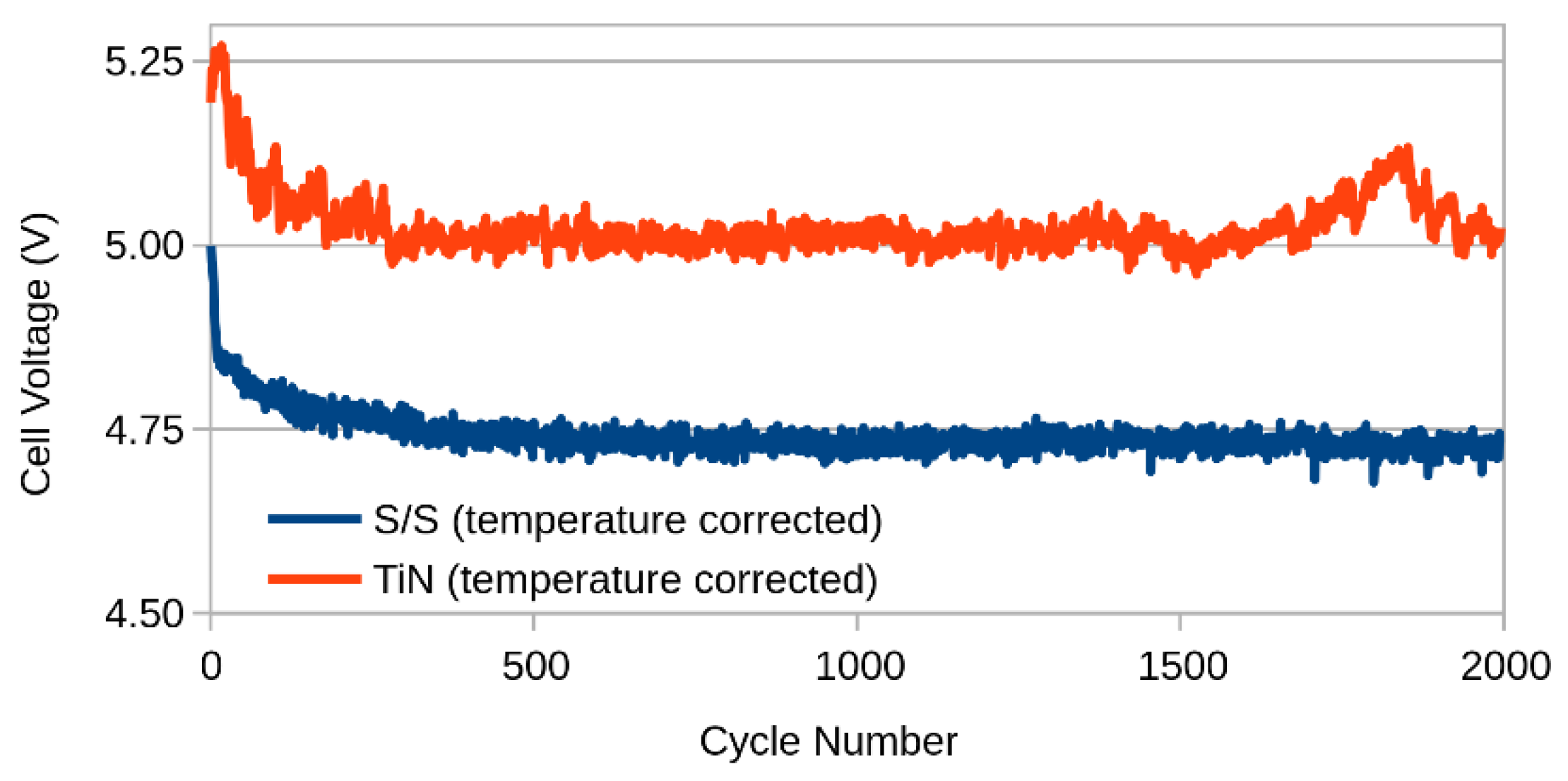
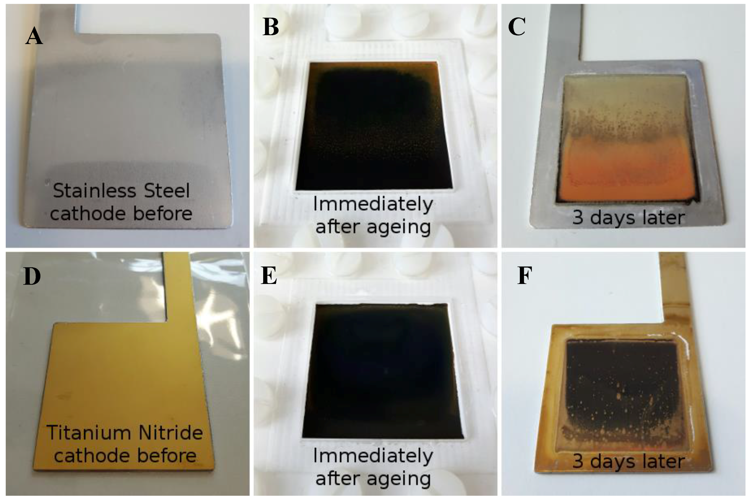
2.2. Ageing
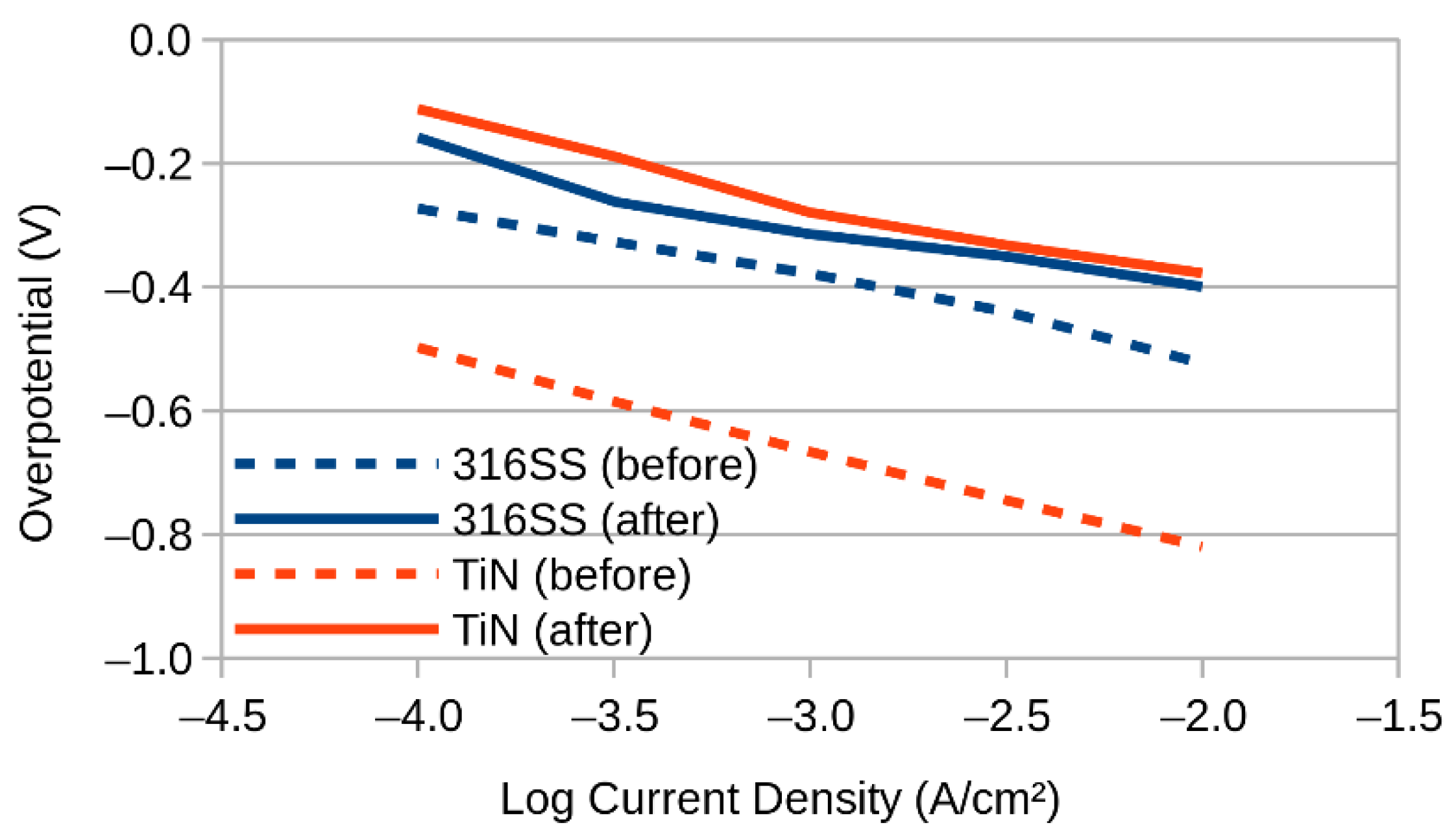
2.3. Three Electrode Experiments
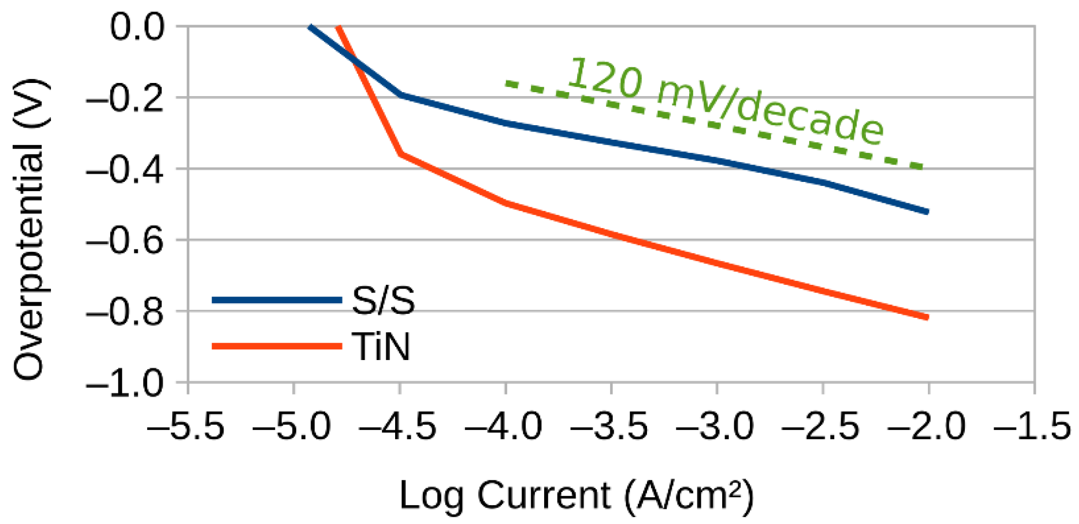
2.4. Tafel Slope
2.5. iR Correction
2.6. Electron Microscope
3. Results and Discussion
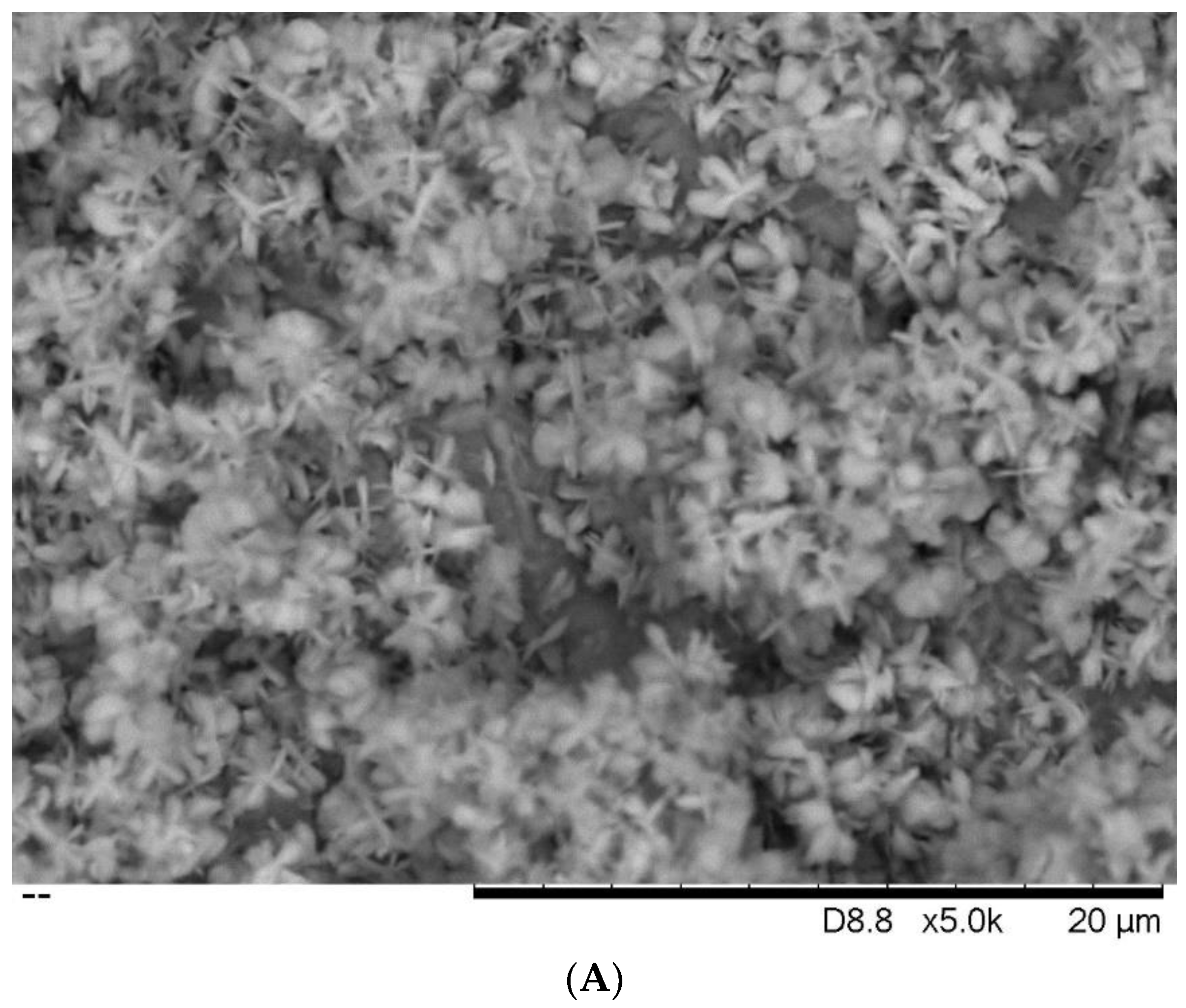
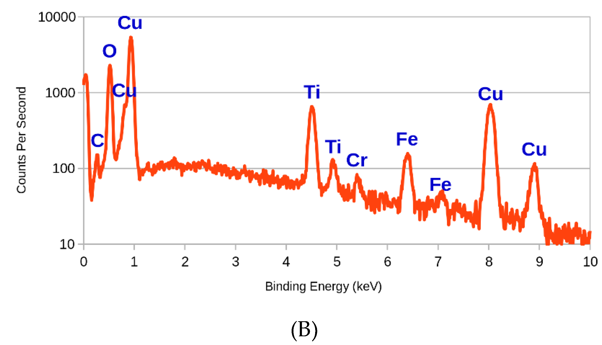
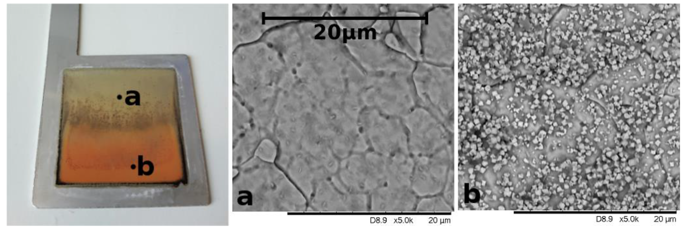
3.1. SEM and EDX
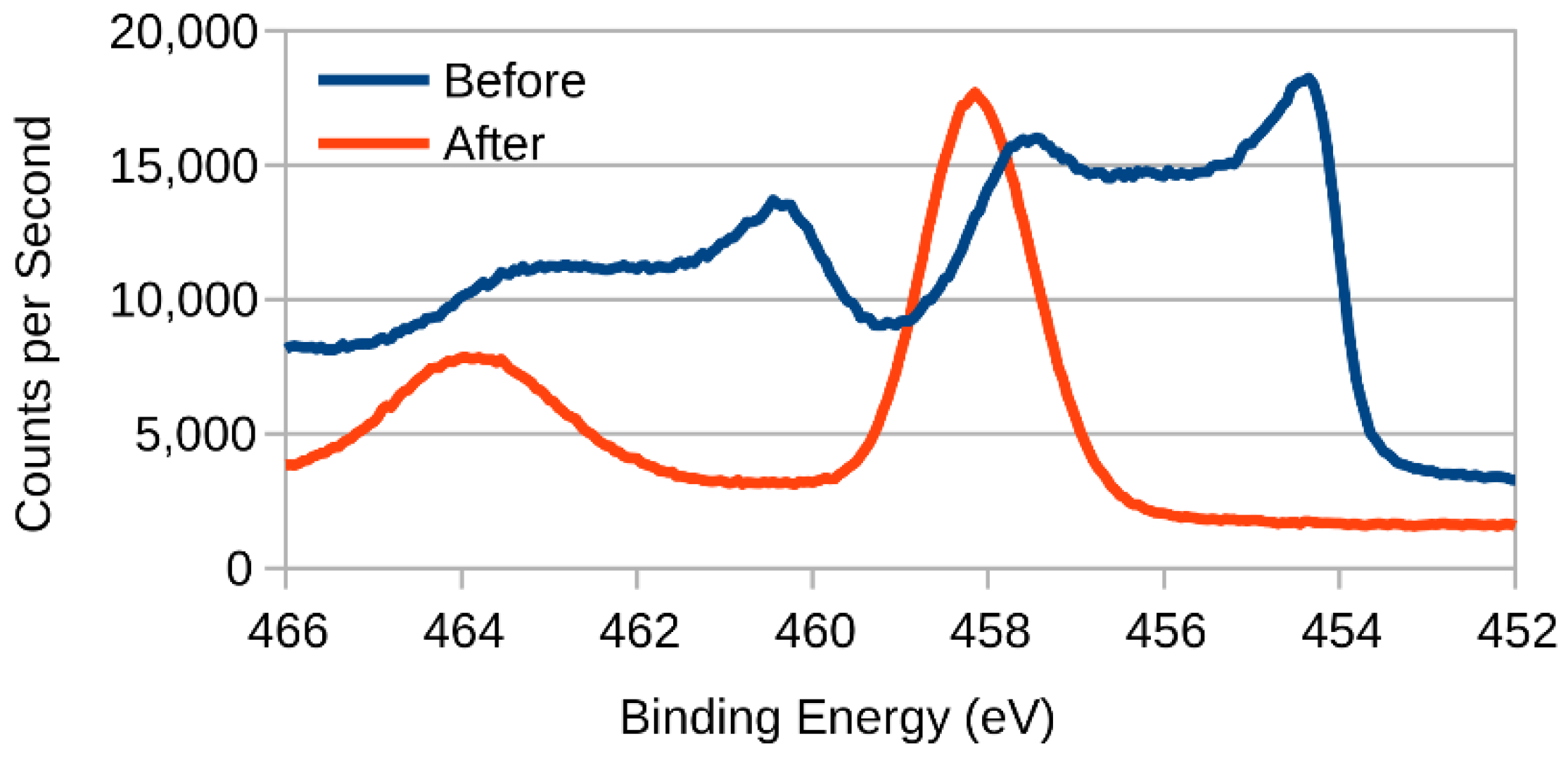
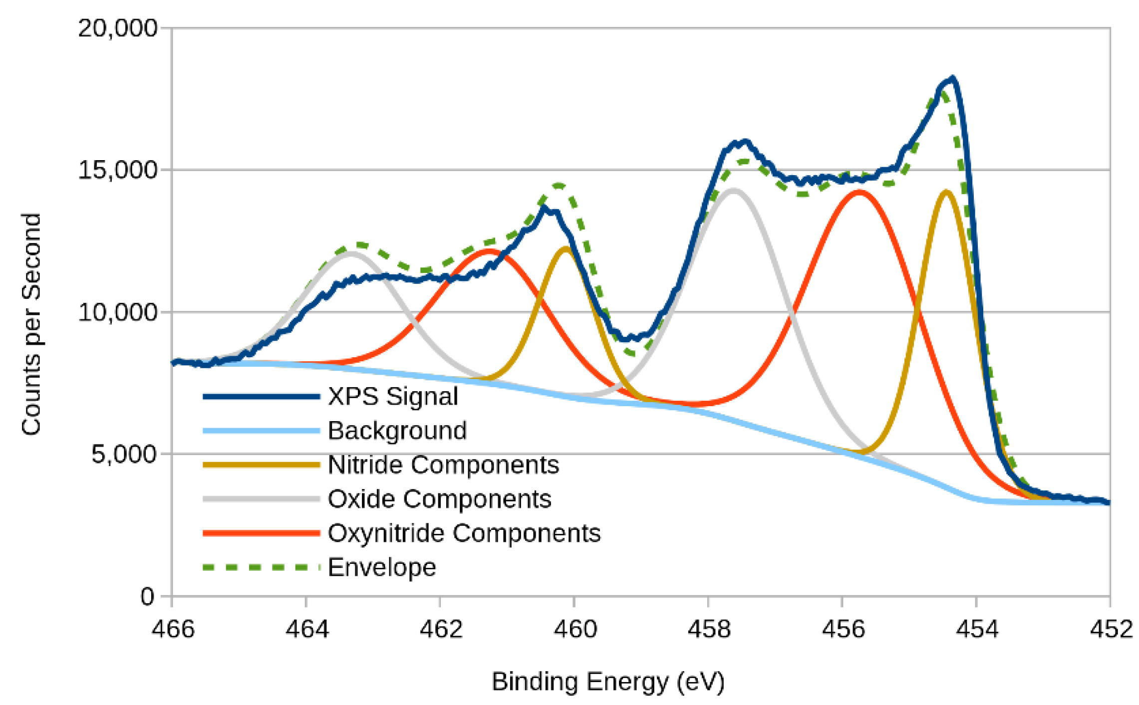
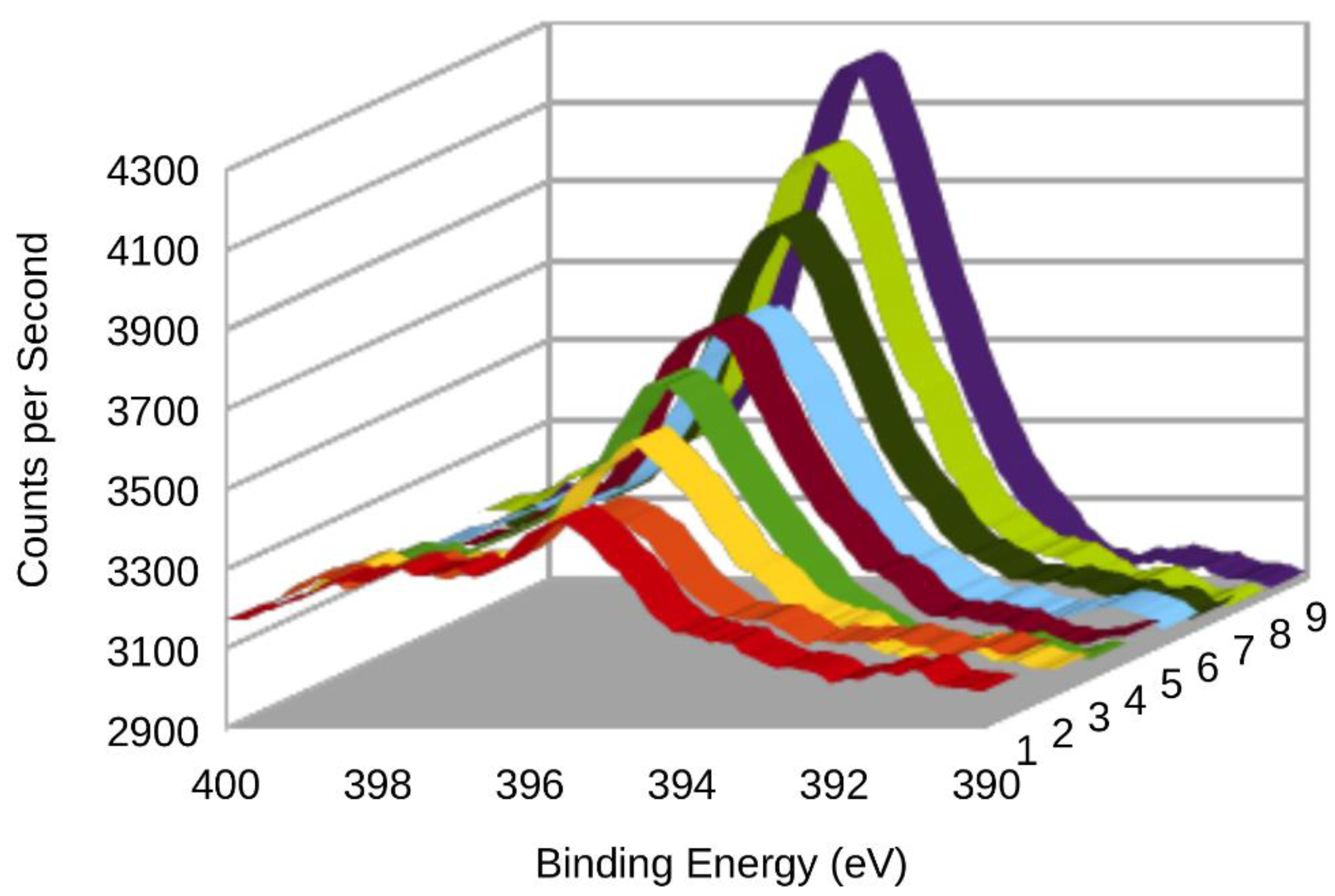
3.2. XPS (X-ray Photoelectron Spectroscopy)
4. Conclusions
Author Contributions
Funding
Acknowledgments
Conflicts of Interest
References
- Mazloomi, K.; Gomes, C. Hydrogen as an energy carrier: Prospects and challenges. Renew. Sustain. Energy Rev. 2012, 16, 3024–3033. [Google Scholar] [CrossRef]
- Sharma, S.; Ghoshal, S.K. Hydrogen the future transportation fuel: From production to applications. Renew. Sustain. Energy Rev. 2015, 43, 1151–1158. [Google Scholar] [CrossRef]
- Maghami, M.R.; Asl, S.N.; Rezadad, M.E.; Ale Ebrahim, N.; Gomes, C. Qualitative and quantitative analysis of solar hydrogen generation literature from 2001 to 2014. Scientometrics 2015, 105, 759–771. [Google Scholar] [CrossRef] [PubMed] [Green Version]
- Gutiérrez-Martín, F.; Confente, D.; Guerra, I. Management of variable electricity loads in wind - Hydrogen systems: The case of a Spanish wind farm. Int. J. Hydrogen Energy 2010, 35, 7329–7336. [Google Scholar] [CrossRef]
- Phillips, R.; Dunnill, C.W. Zero gap alkaline electrolysis cell design for renewable energy storage as hydrogen gas. RSC Adv. 2016, 6, 100643–100651. [Google Scholar] [CrossRef] [Green Version]
- Phillips, R.; Edwards, A.; Rome, B.; Jones, D.R.; Dunnill, C.W. Minimising the ohmic resistance of an alkaline electrolysis cell through effective cell design. Int. J. Hydrogen Energy 2017, 42, 23986–23994. [Google Scholar] [CrossRef]
- Olivares-ramírez, J.M.; Campos-cornelio, M.L.; Godínez, J.U. Studies on the hydrogen evolution reaction on different stainless steels. Int. J. Hydrogen Energy 2007, 32, 3170–3173. [Google Scholar] [CrossRef]
- Carta, R.; Dernini, S.; Polcaro, A.M.; Ricci, P.F.; Tola, G. The influence of sulphide environment on hydrogen evolution at a stainless steel cathode in alkaline solution. J. Electroanal. Chem. 1988, 257, 257–268. [Google Scholar] [CrossRef]
- Schäfer, H.; Beladi-Mousavi, S.M.; Walder, L.; Wollschläger, J.; Kuschel, O.; Ichilmann, S.; Sadaf, S.; Steinhart, M.; Küpper, K.; Schneider, L. Surface Oxidation of Stainless Steel: Oxygen Evolution Electrocatalysts with High Catalytic Activity. ACS Catal. 2015, 5, 2671–2680. [Google Scholar] [CrossRef]
- Devia, D.M.; Restrepo-Parra, E.; Arango, P.J. Comparative study of titanium carbide and nitride coatings grown by cathodic vacuum arc technique. Appl. Surf. Sci. 2011, 258, 1164–1174. [Google Scholar] [CrossRef]
- Cho, E.A.; Jeon, U.-S.; Hong, S.-A.; Oh, I.-H.; Kang, S.-G. Performance of a 1kW-class PEMFC stack using TiN-coated 316 stainless steel bipolar plates. J. Power Sources 2005, 142, 177–183. [Google Scholar] [CrossRef]
- WallworkHT Commercial Coatings (PVD). Available online: https://www.wallworkht.co.uk/content/commercial_coatings/ (accessed on 28 January 2019).
- Pletcher, D.; Li, X. Prospects for alkaline zero gap water electrolysers for hydrogen production. Int. J. Hydrogen Energy 2011, 36, 15089–15104. [Google Scholar] [CrossRef] [Green Version]
- Passas, G.; Dunnill, C.W. Water Splitting Test Cell for Renewable Energy Storage as Hydrogen Gas. Fundam. Renew. Energy Appl. 2015, 5, 3–8. [Google Scholar]
- Stevens, M.B.; Enman, L.J.; Batchellor, A.S.; Cosby, M.R.; Vise, A.E.; Trang, C.D.M.; Boettcher, S.W. Measurement Techniques for the Study of Thin Film Heterogeneous Water Oxidation Electrocatalysts. Chem. Mater. 2016, 29, 120–140. [Google Scholar] [CrossRef]
- Milosev, I.; Strehblow, H.-H.; Navinsek, B. Comparison of TiN, ZrN, and CrN coatings under oxidation.pdf. Thin Solid Films 1997, 303, 246–254. [Google Scholar] [CrossRef]
- Gebauer, C.; Fischer, P.; Wassner, M.; Diemant, T.; Jusys, Z.; Hüsing, N.; Behm, R.J. Performance of titanium oxynitrides in the electrocatalytic oxygen evolution reaction. Nano Energy 2016, 29, 136–148. [Google Scholar] [CrossRef]
- Shinagawa, T.; Garcia-esparza, A.T.; Takanabe, K. Insight on Tafel slopes from a microkinetic analysis of aqueous electrocatalysis for energy conversion. Sci. Rep. 2015, 5, 13801. [Google Scholar] [CrossRef] [PubMed] [Green Version]
- Kao, C.T.; Ding, S.J.; Chen, Y.C.; Huang, T.H. The anticorrosion ability of titanium nitride (TiN) plating on an orthodontic metal bracket and its biocompatibility. J. Biomed. Mater. Res. 2002, 63, 786–792. [Google Scholar] [CrossRef] [PubMed]
- XPS Interpretation of Titanium. Available online: https://xpssimplified.com/elements/titanium.php (accessed on 7 June 2018).
- Shimada, S.; Hasegawa, M. Preparation of Titanium Nitride Films from Amide Precursors Synthesized by Electrolysis. Society 2003, 79, 177–179. [Google Scholar]
- Wang, W.; Savadogo, O.; Ma, Z.F. Preparation of new titanium oxy nitride based electro catalysts using an anhydrous sol-gel method for water electrolysis in acid medium. Int. J. Hydrogen Energy 2012, 37, 7405–7417. [Google Scholar] [CrossRef]
- Chappé, J.M.; Martin, N.; Lintymer, J.; Sthal, F.; Terwagne, G.; Takadoum, J. Titanium oxynitride thin films sputter deposited by the reactive gas pulsing process. Appl. Surf. Sci. 2007, 253, 5312–5316. [Google Scholar] [CrossRef]
- Dunnill, C.W.; Aiken, Z.A.; Pratten, J.; Wilson, M.; Parkin, I.P. Sulfur-and nitrogen-doped titania biomaterials via APCVD. Chem. Vap. Depos. 2010, 16, 50–54. [Google Scholar] [CrossRef]
- Dunnill, C.W.; Ansari, Z.; Kafizas, A.; Perni, S.; Morgan, D.J.; Wilson, M.; Parkin, I.P. Visible light photocatalysts—N-doped TiO2 by sol–gel, enhanced with surface bound silver nanoparticle islands. J. Mater. Chem. A 2011, 21, 11854–11861. [Google Scholar] [CrossRef]
- Dunnill, C.W.; Parkin, I.P. N-Doped Titania Thin Films Prepared by Atmospheric Pressure CVD using t -Butylamine as the Nitrogen Source: Enhanced Photocatalytic Activity under Visible Light. Chem. Vap. Depos. 2009, 15, 171–174. [Google Scholar] [CrossRef]
- Chim, Y.C.; Ding, X.Z.; Zeng, X.T.; Zhang, S. Oxidation resistance of TiN, CrN, TiAlN and CrAlN coatings deposited by lateral rotating cathode arc. Thin Solid Films 2009, 517, 4845–4849. [Google Scholar] [CrossRef]


| Ageing Protocol | Current (mA cm−2) | Cycles | Electrolyte |
|---|---|---|---|
| A | 100 | 2000 to 2500 | 0.5 M NaOH |
| B | 200 | 2000 to 2500 | 1 M NaOH |
| Step | Current Density (A cm−2) | Duration (Seconds) |
|---|---|---|
| 1,14 | 1.0 × 10⁻⁵ | 480 |
| 2,13 | 3.2 × 10⁻⁵ | 480 |
| 3,11 | 1.0 × 10⁻⁴ | 240 |
| 4,10 | 3.2 × 10⁻⁴ | 120 |
| 5,9 | 1.0 × 10⁻³ | 120 |
| 6,8 | 3.2 × 10⁻³ | 120 |
| 7 | 1.0 × 10⁻² | 120 |
| Element | Line Type | Weight % | Sigma | Atomic % |
|---|---|---|---|---|
| Cu | L series | 61.00 | 0.58 | 31.84 |
| O | K series | 24.07 | 0.38 | 49.90 |
| Ti | K series | 6.86 | 0.15 | 4.75 |
| Fe | K series | 3.30 | 0.16 | 1.96 |
| C | K series | 3.28 | 0.36 | 9.05 |
| N | K series | 0.90 | 0.64 | 2.13 |
| Cr | K series | 0.60 | 0.09 | 0.38 |
| Total | 100.01 | |||
© 2019 by the authors. Licensee MDPI, Basel, Switzerland. This article is an open access article distributed under the terms and conditions of the Creative Commons Attribution (CC BY) license (http://creativecommons.org/licenses/by/4.0/).
Share and Cite
Gannon, W.J.F.; Jones, D.R.; Dunnill, C.W. Enhanced Lifetime Cathode for Alkaline Electrolysis Using Standard Commercial Titanium Nitride Coatings. Processes 2019, 7, 112. https://doi.org/10.3390/pr7020112
Gannon WJF, Jones DR, Dunnill CW. Enhanced Lifetime Cathode for Alkaline Electrolysis Using Standard Commercial Titanium Nitride Coatings. Processes. 2019; 7(2):112. https://doi.org/10.3390/pr7020112
Chicago/Turabian StyleGannon, William J. F., Daniel R. Jones, and Charles W. Dunnill. 2019. "Enhanced Lifetime Cathode for Alkaline Electrolysis Using Standard Commercial Titanium Nitride Coatings" Processes 7, no. 2: 112. https://doi.org/10.3390/pr7020112