Article

Numerical Study on Separation Performance of Cyclone Flue Used in Grate Waste Incinerator

1
Key Laboratory of Low-grade Energy Utilization Technologies and Systems, Chongqing University, Chongqing 400044, China
2
School of Energy and Power Engineering, Chongqing University, Chongqing 400044, China
3
Coll Comp Sci & Informat Engn, Chongqing Technol & Business University, Chongqing 400067, China
*
Author to whom correspondence should be addressed.
Processes 2019, 7(12), 866; https://doi.org/10.3390/pr7120866
Submission received: 9 September 2019 / Revised: 7 November 2019 / Accepted: 8 November 2019 / Published: 20 November 2019
(This article belongs to the Special Issue Gas, Water and Solid Waste Treatment Technology)

Abstract

:
The traditional treatment of waste incineration flue gas is mostly carried out in low temperatures, but there are some problems such as corrosion of the heating surface at high and low temperatures, re-synthesis of dioxins, and low efficiency. Therefore, it is necessary to remove the pollutants at high temperatures. For the grate waste incinerator, this study proposes an adiabatic cyclone flue arranged at the exit of the first-stage furnace of the grate waste incinerator to pre-remove the fly ash at high temperatures, so as to alleviate the abrasion and corrosion of the tail heating surface. In this paper, computational fluid dynamics (CFD) method is applied to study the performance of a cyclone flue under different structural parameters, and the comprehensive performance of the cyclone flue is evaluated by the technique for order preference by similarity to an ideal solution (TOPSIS) method. The results show that particle separation efficiency increases at first and then decreases with the increase of the vortex finder length, the vortex finder diameter, and the distance between vortex finder and gas outlet tube, while it decreases with the increase of the gas outlet tube diameter. The pressure drop increases with the increase of the vortex finder length, and the vortex finder diameter, while decreases with the increase of the distance between the vortex finder, the gas outlet tube, and the gas outlet tube diameter. In the scope of this study, when h1/a = 1.1, D1/A = 0.33, h2/A = 1.5, and D2/A = 0.50, the comprehensive performance of the cyclone flue is much better.

Graphical Abstract

1. Introduction

In recent years, waste incineration technology has been widely used in the world by virtue of reduction (about 90% reduction in volume, 70% reduction in weight), harmlessness, and energy recovery [1,2]. Due to the complex compositions of waste, a variety of harmful gases and toxic substances will be formed during the incineration process. These are inorganic acid gases such as HCl, HF, NOx, SO2, and gaseous heavy metals such as mercury, highly toxic organic substances like Polycyclic Aromatic Hydrocarbons (PAHs), Polychlorinated Biphenyls (PCBs), Polychlorinated Dibenzo-Dioxins/Polychlorinated Dibenzofurans (PCDD/PCDFs), fly ash which equivalent to 2–5% of the original waste weight and required for special treatment [3,4,5]. Therefore, secondary pollution problem is urgent to be solved in the waste incineration process.
The traditional treatment of flue gas is mostly to remove the pollutants at low temperatures (100–350 °C), and the process is very complicated. The corrosion of superheater caused by acid gases and fly ash in incineration flue gas at high temperatures limits the further improvement of steam parameters and power generation efficiency [6]. In addition, the low temperature environment is easy to promote the re-synthesis of dioxins, and the presence of chlorine and heavy metals in fly ash provide favorable conditions for dioxins re-synthesis [7,8,9,10]. Therefore, it is necessary to pre-remove acidic gases and fly ash from flue gas at high temperatures.
The grate waste incinerator is the mainstream equipment for waste incineration [11,12]. At present, the grate waste incinerator relies on a three-stage furnace to reduce the flue gas temperature at the entrance of convective heating surface generally. In order to prevent corrosion at low temperatures, the flue gas temperature at the exit of the waste heat boiler is approximately designed to be at temperatures between 190–230 °C, which will limit the improvement of the efficiency of waste heat boiler. According to the structural characteristics of the grate waste incinerator, this research proposes a square adiabatic cyclone flue arranged at the first-stage furnace exit of the grate waste incinerator (as shown in Figure 1) to pre-remove the fly ash in the flue gas. In addition, calcium and ammonia can be injected into the flue to remove acidic gases synergistically, which alleviates corrosion of heating surface at high and low temperatures, as well as inhibits dioxin formation and improves furnace parameters. In order to facilitate the arrangement, the cyclone flue is designed as a square, and downward exhaust is adopted to conform to the flow direction of flue gas in the grate waste incinerator, the original grate waste incinerator can be reformed directly. There is no heating surface inside the flue, the inner layer is refractory, and the outer layer is insulation materials. These can prevent heat loss and ensure that the flue gas exists at a higher temperature, which can crack dioxins effectively. In order to understand the flow field characteristics and gas–solid separation performance of cyclone flue, this paper simulates the internal flow field and gas–solid separation performance of cyclone flue with the CFD method.
The adiabatic cyclone flue proposed in this paper is similar in structure to the cyclone separator, so the simulation method of the cyclone separator can be referred to. The traditional cyclone separator is circular and has an upper exhaust, which has been subjected to a large number of experiments and numerical studies by many researchers, and the research methods are relatively reasonable and reliable. Xiang et al. [13] used the Reynold’s stress model (RSM) to simulate the internal flow field of cyclone separators with different heights. The results showed that as the height of the cyclone separator increases, the tangential velocity will decrease, then the centrifugal force on the particles is reduced, which will result in a decrease in dust removal performance. Raoufi et al. [14] studied the effect of the gas outlet tube structure on the separation efficiency of the cyclone separator based on the Euler–Lagrangian method; the results indicated that the separation efficiency of the separator decreases with the increase of the diameter of gas outlet tube. Moreover, Safikhani et al. [15] applied a simple pressure correction algorithm, using the Reynold’s stress turbulence model and the random walk model to study the internal flow field and particle motion trajectory of cyclone separators with different number of inlets. In addition, Sakura et al. [16] used the large eddy simulation (LES) model, based on Ansys CFX to study the gas–solid flow characteristics of cyclone separators, and compared the effects of different dust outlet shapes on separation efficiency and pressure drop. Zhang et al. [17] used the transient Reynold’s stress model and discrete phase model to study the flow field and particle motion trajectory in the cyclone separator, and proposed a new cyclone separator, which can improve efficiency and reduce pressure drop. Furthermore, Parvaz et al. [18] studied the performance of a cyclone separator which had an inner cone located at the bottom of the cyclone, and simulated the influence of the inner cone with different heights and diameters on the performance of the separator.
Compared to conventional cyclone separator, there is less research on square and downward exhaust cyclones. Safikhani et al. [19] compared the internal flow field, separation efficiency of a square cyclone separator and a circular cyclone separator based on the CFD method, the results showed that the separation efficiency of the square cyclone separator is lower than the circular cyclone separator, but the pressure drop is rather small. Su et al. [20] used the Euler–Lagrange method to simulate the gas–solid flow characteristics of three inlet structures of square cyclones. Raoufi et al. [21] studied the internal flow field of a square cyclone separator by numerical simulation method, and analyzed the similarities and differences of the internal flow field of the upper exhaust type and the downward exhaust type cyclone separator. Moreover, Oh et al. [22] investigated the internal flow field and particle separation efficiency of the downward exhaust cyclone based on the Euler–Lagrange method. Fatahian et al. [23] studied the performance that using the laminarizer in the square and circular cyclones, the results suggested that square cyclone is more effective. Additionally, Mokni et al. [24] used the CFD method to study the effects of cylinder height on flow field, pressure drop and separation performance in a turbulent hydrocyclone.
Here we simulated by way of a realizable k-ε model and random walk model. Firstly, the geometric model and mathematical model are described, then the internal flow field characteristics of the cyclone flue and the influence of various structural parameters on the separation performance and pressure drop are analyzed, finally, the comprehensive performance of the cyclone flue is evaluated by technique for order preference by similarity to an ideal solution (TOPSIS) method.

2. Model Description

2.1. Adiabatic Cyclone Flue Model

As shown in Figure 1, the cyclone flue distributes along the width of the grate waste incinerator evenly, and each adiabatic cyclone flue works independently without any influence on each other, so only one of the flues needs to be studied. Its structure is shown in Figure 2. In this paper, the influences of the vortex finder diameter, vortex finder length, distance between vortex finder and gas outlet tube, gas outlet tube diameter on the performance of cyclone flue were studied. The dimensions of each cyclone flue are given in Table 1. In order to reduce the computational complexity, the numerical studies only were carried out on the parts above the cone. The study of Oh et al. [22] showed that neglecting the cone part has little effect on the results and can be neglected.

2.2. Governing Equation

The CFD method was used to simulate a three-dimensional flow field in the adiabatic cyclone flue. For steady incompressible flow, the continuity equation and momentum equation are as follows:
u ¯ i x ¯ i = 0
u ¯ j u ¯ i x j = 1 ρ P ¯ x i + v 2 u ¯ i x j x j x j R i j
In the above equations, u ¯ i is the average velocity of the fluid; xi is the coordinate position; P ¯ is the average pressure; ρ is the fluid density; v is the kinematic viscosity of the fluid; R i j = u i u j ¯ , is the Reynold’s stress tensor, which represents the influence of turbulence on the flow field, here, u i = u i u ¯ i .
The turbulence models for cyclone separator simulation were the k-ε (standard, RNG, realizable) model and the Reynold’s stress model (RSM) commonly. In this paper, the realizable k-ε model was adopted, the transport equations of turbulent kinetic energy (k) and turbulent dissipation rate (ε) were as follows:
t ( ρ k ) + x j ( ρ k u j ) = x j [ ( μ + μ t σ k ) k x j ] + G k ρ ε
t ( ρ ε ) + x j ( ρ ε u j ) = x j [ ( μ + μ t σ ε ) ε x j ] ρ C 2 ε 2 k + v ε
In the above equations, Gk represents the turbulent energy generated by the velocity gradient; μ is the dynamic viscosity of the fluid; C2 is a constant; σk, and σε are turbulent Prandtl numbers in k equation and ε equation respectively.
There are two main methods simulating gas–solid two-phase flow. They are the Euler–Euler method and the Euler–Lagrange method. In order to track the trajectory of particles, the Euler–Lagrange method was used to simulate gas–solid two-phase flow. In this method, gases were regarded as continuous phase and particles as dispersed discrete phase. Because the particle concentration was small, it belonged to the dilute phase flow and the particle size was small too, so the influence of particle on flow field can be neglected, unidirectional coupling mode was adopted in this paper, and the interaction force between particles was ignored. In Lagrangian coordinates, the force balance equations of particles are as follows:
d u p d t = F D ( u A u p ) x + g x ( ρ p ρ A ) ρ p
F D = 18 μ A ρ p d p 2 C D Re p 24
C D = C 1 + C 2 R e p + C 3 Re p
R e p = ρ A d p | u p u A | μ A
In the above equations, uA is the fluid velocity; up is the particle velocity; μA is the fluid dynamic viscosity; dp is the particle diameter; ρp is the particle density; ρA is the fluid density; Rep is the relative Reynold’s number (particle Reynold’s number); CD is the resistance coefficient; C1C3 is a constant, depending on Reynolds number; gx is the gravitational acceleration.

2.3. Boundary Conditions and Numerical Schemes

Semi-implicit method pressure-linked equations consistent (SIMPLEC) were used as a method for pressure-velocity coupling. The Pressure staggering option (PRESTO) was used for pressure interpolation. The quadratic upstream interpolation for convective kinetics (QUICK) was used for discrete difference format.
In this paper, we assumed that the gas flow enters the flue at a constant velocity, the gas phase is a high temperature flue gas, its temperature is 850 °C, its velocity is 20 m/s, and the particles and fluids have the same inlet velocity. The setting of specific boundary conditions are shown in Table 2, non-slip adiabatic boundary conditions are adopted for all walls.

2.4. Grid Independence Study

In this paper, the structured hexahedral mesh of cyclone flue was generated by ICEM. In order to ensure the accuracy of calculation and shorten the calculation time, five different numbers of structured grids were generated to verify the irrelevance between the calculated results and the number of grids, which are 890,000 cells, 1,190,000 cells, 1,400,000 cells, 1,670,000 cells and 1,960,000 cells. Figure 3 shows the weighted average turbulence intensity (I) and weighted average turbulent kinetic energy (K) at z = 1.5 m cross section area under different mesh numbers, with the increase of the number of grids, the values of K and I decreased gradually, the differences between the 1,670,000 grids and the 1,960,000 grids were 0.17% and 0.06% respectively, indicating that the number of grids had little impact on the calculation results. The model with 1,670,000 grids is selected for numerical simulation.

2.5. Model Validation

In order to verify the accuracy of the model, the flow characteristics were compared with the experimental data of Su [26]. Su et al. measured the axial velocity distribution of Plane 1 at an inlet velocity of 25.3 m/s using a particle dynamic analyzer (PDA). The geometric model is shown in Figure 4.
Figure 5 compares the computed axial velocity at different positions in Plane 1 with the corresponding experimental data of Su. The two positions were x = 30 mm and x = 90 mm. It is clearly seen that the model prediction was in close quantitative agreement with the experimental data. Overall, the adopted model can accurately and reliably predict the performance of the cyclone flue.

3. Results and Discussion

3.1. Characteristics of Flow Field

Figure 6a shows the velocity distribution of the cyclone flue at z = 1.5 m cross section. It can be seen from the figure that the maximum velocity appeared at the entrance of the gas outlet tube. The velocity below the vortex finder was lower, because the recirculation zone was formed here. The obvious flow separation was found at the edge of the vortex finder near the inlet, resulting in a lower velocity. Oh et al. [22] also found this phenomenon in the simulation of a circular uniflow cyclone. The gas flow went into the flue and rotated around the vortex finder, flow separation appeared due to the centrifugal and inertial forces, and this phenomenon was weakened gradually in the downstream direction.
Figure 6b shows the static pressure distribution of the cyclone flue at z = 1.5 m cross section. It can be seen from the figure that the static pressure distributed symmetrically around the central axis, which is similar to traditional cyclone separators [14,27]. Along the radius, the pressure decreased slowly, thus forming a low pressure zone in the center. The minimum static pressure appeared at the entrance of the gas outlet tube, reaching −1750 Pa. Combined with the velocity distribution, it can be seen that the fluid velocity reached the highest here, and the static pressure was converted into dynamic pressure.
Figure 7 shows the velocity vector diagram of cyclone flue at y = 9 m cross section. It can be seen from the figure that when the gas flow went into the flue from the inlet, the velocity increased firstly, and then decreased gradually in the course of the flow. There was a strong eddy at the corner facing the inlet, which has been confirmed in Su’s discovery [20]. As the gas flow goes into the flue, it impinged the corner opposite the inlet directly, and the sharp changed the flow direction at the corner, causing the local vortex. Some particles were collected in the corner and fell down, while some particles were rebounded in the corner and rotated continuously. In the other corners, there was also a weaker local vortex.

3.2. Particle Separation Efficiency and Pressure Drop

Particle separation efficiency and pressure drop are two important indices to study the performance of the adiabatic cyclone flue. This paper used the control variable method to study the effects of structural parameters such as vortex finder length (h1), vortex finder diameter (D1), distance between vortex finder and gas outlet tube (h2), and gas outlet tube diameter (D2) on the separation performance and pressure drop of the cyclone flue, which provided guiding significance for the optimal design of the cyclone flue. According to the literature [28,29,30], the particle size of fly ash in the waste incineration flue gas ranged from 1 to 100 μm, which can be assumed that the particle size follows the Rosin–Rammler distribution.

3.2.1. The Influence of the Vortex Finder Length

Figure 8 shows the effects of the vortex finder length on the separation efficiency and pressure drop of the cyclone flue, and the h1/a varying from 1.1 to 1.5. It can be seen from the figure that the separation efficiency increased firstly and then decreased with the increase of the vortex finder length. There was an optimum value in the middle. When h1/a = 1.2, the separation efficiency reached its highest point. The pressure drop increased linearly with the increase of the vortex finder length, and the increase ratio was about 1.5%. The experiments conducted by Trieseh et al. also found that the pressure drop increased proportionally to the vortex finder length [31].
The function of the vortex finder was mainly embodied in two aspects. On the one hand, the gas flow was rotated under the guidance of the vortex finder. On the other hand, the annular space formed by the vortex finder and the body affected the rotation speed of gas flow. As the increase of the vortex finder length appropriated, enough time was ensured to separate particles to the wall. However, if the vortex finder length was too long, it caused back-flushing of the bottom due to the extension of the swirling gas flow, and resulted in a decrease in separation efficiency. The longer the length of vortex finder was, the larger the area of the wall contacted with the gas flow was. The rotational kinetic energy loss of the gas flow increased due to friction, resulting in an increase in the pressure drop.

3.2.2. The Influence of the Vortex Finder Diameter

Figure 9 shows the effects of the vortex finder diameter on the separation efficiency and pressure drop of the cyclone flue, and the D1/A varying from 0.33 to 0.47. It can be seen from the figure that the separation efficiency increased firstly and then decreased with the increase of the vortex finder diameter. While D1/A= 0.4, the separation efficiency was the highest, reaching to 77.2%. The pressure drop increased with the increase of vortex finder diameter, but while D1/A was higher than 0.4, the change of the diameter of vortex finder had little effect on the pressure drop. Compared with the vortex finder length, the vortex finder diameter had a weaker influence on the pressure drop.
With the increase of the vortex finder diameter, the annular cross-section area of the vortex finder was reduced, and the velocity of the flow increased when entering the flue, in addition, the centrifugal force strengthened, which helped to improve separation efficiency. In addition, the increase in velocity of flow led to an increase in the loss of rotational kinetic energy, resulting in an increase in pressure loss. However, the too large vortex finder diameter led to the impact of part of the gas flow on the vortex finder directly, resulting in the deterioration of the flow field and the rebound of particles, which was not conducive to the separation of particles.

3.2.3. The Influence of the Gas Outlet Tube Diameter

Figure 10 shows the effects of gas outlet tube diameter on separation efficiency and the pressure drop of the cyclone flue, and the D2/A varying from 0.33 to 0.5. It can be seen from the figure that the separation efficiency decreased with the increase of the gas outlet tube diameter. But in the range of 0.33–0.4 and 0.43–0.5, the variation range of separation efficiency was small, while D2/A increased from 0.4 to 0.43, the separation efficiency decreased from 77.2% to 75.8%. Compared with the vortex finder, the gas outlet tube diameter had a greater influence on the pressure drop. When D2/A increased from 0.33 to 0.5, the pressure drop decreased from 2065 Pa to 934 Pa, and the variation decreased gradually.
The entrance of the gas outlet tube was a high-speed and low-pressure area, as shown in Figure 6, and the gas flow converged here. If the diameter of gas outlet tube was small, the fly ash particles collided with the wall of gas outlet tube easily when the particles moved to the entrance of the gas outlet tube, and then falling into the hopper and being separated, which helped to improve the separation efficiency. With the increase of the diameter of the gas outlet tube, the phenomenon of the flow rate rising sharply when the gas reached the gas outlet tube was alleviated, thus making the flow field more stable.

3.2.4. The Influence of the Distance between Vortex Finder and Gas Outlet Tube

Figure 11 shows the effects of the distance between vortex finder and gas outlet tube on the separation efficiency and pressure drop of the cyclone flue, and the h2/A varying from 0.83 to 1.5. It can be seen from the figure that the separation efficiency increased at first and then decreased with the increase of the distance between the vortex finder and the gas outlet tube. When h2/A = 1.33, the separation efficiency was the highest, reaching to 76.5%. The pressure drop decreased linearly with the increase of the distance between the vortex finder and the gas outlet tube, and the reduction ratio was about 5%.
Gauthier studied the effect of the length of the separation section (the sum of h1 and h2) on the performance of the uniflow cyclone. The results showed that the separation efficiency increased first and then decreased with the increase of the separation section [32].
As the increase in the distance between the vortex finder and gas outlet tube appropriated, it allowed enough time for particles to converge into the wall. However, the excessive distance led the particles that have been separated to re-enter the central gas flow and escape from the gas outlet tube. In addition, the longer the distance between the vortex finder and gas outlet tube was, and the shorter the length of the gas outlet tube was then the weaker the interference to the flow field was, which made the flow field more stable and decreased the pressure loss.

3.3. Comprehensive Performance Evaluation

The highest separation efficiency and the lowest pressure drop cannot always exist at the same time, it is necessary to analyze and evaluate the comprehensive performance of the cyclone flue, and to ensure high efficiency and low energy loss. The TOPSIS evaluation method is a scientific method used in multi-objective decision analysis of limited schemes commonly, and it was developed by Yoon and Hwang [33]. This method has no special requirement on the sample data, it can make full use of the original data, and it can obtain better results [34,35,36]. Therefore, this method was used to analyze and evaluate the comprehensive performance of the cyclone flue in this study. The steps of the TOPSIS model were as follows:
(1)
Establish the initial decision matrix X = {xij}. Two evaluation indexes of separation efficiency and pressure drop of cyclone flue were considered, and xij is the j-th evaluation index of the i-th evaluation object.
(2)
Assimilation of indicator attributes. The inverse method was used to convert low-quality indicators into high-quality indicators, that is, the higher the value is, the better the performance will be. The pressure drop was a low-quality indicator, which needed to be converted into a high-quality indicator to obtain a new matrix X’.
(3)
Calculating the standard decision matrix Z. The dimensionless processing of each indicator can eliminate the effects of dimension and magnitude between different attribute indicators. The equation was as follows:
z i j = x i j / i = 1 m x i j 2
(4)
Calculate the set of positive ideal (S+) and negative ideal (S) solutions of the decision matrix. S+ is the set of maximum values of each index, that is, when the separation efficiency of the cyclone flue is the highest, the pressure drop will be the smallest. S is the set of minimum values of each index, that is, when the efficiency is lowest, the pressure drop will be largest.
(5)
Calculating the Euclidean distances of each evaluation scheme to the S+ and S. The equations are as follows:
d i + = j = 1 n ( s j + z i j ) 2
d i = j = 1 n ( s j z i j ) 2
(6)
Calculating the relative proximity (Ci) of each evaluation scheme to the S+. The equation is as follows:
C i = d i / ( d i + + d i )
(7)
Ranking according to the value of Ci. the larger the value of Ci is, the closer the scheme to S+ and the farther away from S, the better the scheme is.
In this paper, the vortex finder length, the vortex finder diameter, the gas outlet tube diameter, and the distance between the vortex finder and the gas outlet tube were taken as the evaluation objects. The Ci values were calculated under different structural parameters. The calculation results are listed in Table 3.
According to the data in Table 3, the comprehensive performance of the cyclone flue was negatively correlated with the vortex finder diameter and the vortex finder length, while it was positively correlated with the distance between the vortex finder and the gas outlet tube, and gas outlet tube diameter. When designing the cyclone flue, the vortex finder diameter and the vortex finder length should be adopted to smaller values, but the distance between the vortex finder and the gas outlet tube, and the gas outlet tube diameter, should be taken to a larger value. In the scope of this study, when h1/a = 1.1, D1/A = 0.33, h2/A = 1.5, D2/A = 0.50, the separation efficiency reached to 75% and the pressure drop was about 900 Pa, reaching a better comprehensive performance.

4. Conclusions

In this paper, the internal flow field and performance of the adiabatic cyclone flue were studied by the CFD method. The effects of the vortex finder diameter, vortex finder length, distance between vortex finder and gas outlet tube, and gas outlet tube diameter on the separation efficiency and pressure drop of cyclone flue were also studied. Then the TOPSIS method was applied to evaluate the comprehensive performance of the cyclone flue. The main conclusions are shown as follows:
(1)
The inlet of the gas outlet tube of the cyclone flue was a high-speed and low-pressure zone, where the velocity was the largest and the pressure was the smallest. The internal pressure was symmetrically distributed along the central axis, which is consistent with the conventional cyclone. In addition, there was a local vortex at the corner in the flue.
(2)
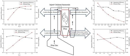
The particle separation efficiency increased at first and then decreased with the increase of the vortex finder length, the vortex finder diameter, and the distance between the vortex finder and the gas outlet tube, while it decreased with the increase of the gas outlet tube diameter. Above all, the gas outlet tube diameter had the most important influence on the separation efficiency.
(3)
The pressure drop increased with the increase of the vortex finder length, and the vortex finder diameter, while it decreased with the increase of the distance between vortex finder and gas outlet tube, and the gas outlet tube diameter. In addition, the gas outlet tube diameter had the greatest influence on the pressure drop.
(4)
The comprehensive performance of the cyclone flue was negatively correlated with the vortex finder diameter and the vortex finder length, while it was positively correlated with the distance between the vortex finder and the gas outlet tube, and the gas outlet tube diameter.
(5)
In the scope of this study, when h1/a = 1.1, D1/A = 0.33, h2/A = 1.5, D2/A = 0.50, the comprehensive performance of the cyclone flue was better, and the separation efficiency reached to 75%, which can remove the fly ash in the flue gas effectively, alleviate erosion wear and ash corrosion of the tail heating surface, and reduce the burden of the bag filter.

Author Contributions

Conceptualization, D.-m.C., J.-y.R. and L.Y.; methodology, D.-m.C., J.-y.R., J.-t.N. and Z.-q.Y.; software, D.-m.C. and J.-t.N.; validation, D.-m.C., J.-y.R. and J.-t.N.; formal analysis, Z.-q.Y. and G.P.; investigation, D.-m.C. and J.-t.N.; resources, J.-y.R., G.P. and L.Y.; data curation, D.-m.C. and Z.-q.Y.; writing—original draft preparation, D.-m.C.; writing—review and editing, J.-t.N. and J.Y.R; visualization, G.P. and Z.-q.Y.; supervision, L.Y.; project administration, J.-y.R.; funding acquisition, J.-y.R.

Funding

This research was funded by KEY INDUSTRIAL GENERIC TECHNOLOGY INNOVATION PROJECT OF CHONGQING, grant number Cstc2016zdcy-ztzx20006.

Conflicts of Interest

The authors declare no conflicts of interest.

Abbreviations

Nomenclature
Abody edge length (m)
ainlet height (m)
binlet width (m)
linlet length (m)
h1vortex finder length (m)
D1vortex finder diameter (m)
h2distance between vortex finder and gas outlet tube (m)
D2gas outlet tube diameter (m)
Hcyclone flue height (m)
uvelocity (m/s)
Ppressure (Pa)
ρdensity (kg/m3)
νkinematic viscosity (m2/s)
μdynamic viscosity (Pa·s)
kturbulent kinetic energy (m2/s2)
εturbulent dissipation rate (m2/s3)
σturbulent Prandtl number
Reprelative Reynold’s number
gxgravitational acceleration (m/s2)
Iturbulence intensity (%)
Cirelative proximity coefficient

References

  1. Li, M.; Xiang, J.; Hu, S.; Sun, L.S.; Su, S.; Li, P.S.; Sun, X.X. Characterization of solid residues from municipal solid waste incinerator. Fuel 2004, 83, 1397–1405. [Google Scholar] [CrossRef]
  2. He, J.; Lin, B. Assessment of waste incineration power with considerations of subsidies and emissions in China. Energy Policy 2019, 126, 190–199. [Google Scholar] [CrossRef]
  3. Niu, J.; Liland, S.E.; Yang, J.; Rout, K.R.; Ran, J.; Chen, D. Effect of oxide additives on the hydrotalcite derived Ni catalysts for CO2 reforming of methane. Chem. Eng. J. 2019, 377, 119763. [Google Scholar] [CrossRef]
  4. Makarichi, L.; Jutidamrongphan, W.; Techato, K.A. The evolution of waste-to-energy incineration: A review. Renew. Sustain. Energy Rev. 2018, 91, 812–821. [Google Scholar] [CrossRef]
  5. Wang, P.; Hu, Y.; Cheng, H. Municipal solid waste (MSW) incineration fly ash as an important source of heavy metal pollution in China. Environ. Pollut. 2019, 252, 461–475. [Google Scholar] [CrossRef] [PubMed]
  6. Valente, T. Fireside corrosion of superheater materials in chlorine containing flue gas. J. Mater. Eng. Perform. 2001, 10, 608–613. [Google Scholar] [CrossRef]
  7. Stieglitz, L.; Bautz, H.; Roth, W.; Zwick, G. Investigation of precursor reactions in the de-novo synthesis of PCDD/PCDF on fly ash. Chemosphere 1997, 34, 1083–1090. [Google Scholar] [CrossRef]
  8. Gullett, B.K.; Bruce, K.R.; Beach, L.O.; Drago, A.M. Mechanistic steps in the production of PCDD and PCDF during waste combustion. Chemosphere 1992, 25, 1387–1392. [Google Scholar] [CrossRef]
  9. Zhang, Z.E.; Yan, Y.F.; Zhang, L.; Ju, S.X. Hollow fiber membrane contactor absorption of CO2 from the flue gas: Review and perspecrive. Glob. Nest J. 2014, 16, 354–373. [Google Scholar]
  10. Niu, J.; Du, X.; Ran, J.; Wang, R. Dry (CO2) reforming of methane over Pt catalysts studied by DFT and kinetic modeling. Appl. Surf. Sci. 2016, 376, 79–90. [Google Scholar] [CrossRef]
  11. Wissing, F.; Wirtz, S.; Scherer, V. Scherer. Simulating municipal solid waste incineration with a DEM/CFD method-Influences of waste properties, grate and furnace design. Fuel 2017, 206, 638–656. [Google Scholar] [CrossRef]
  12. Zhang, N.; Pan, Z.; Zhang, Z.; Zhang, W.; Zhang, L.; Baena-Moreno, F.M.; Lichtfouse, E. CO2 capture from coalbed methane using membranes: A review. Environ. Chem. Lett. 2019, 8, 1–18. [Google Scholar] [CrossRef]
  13. Xiang, R.B.; Lee, K.W. Numerical study of flow field in cyclones of different height. Chem. Eng. Process. 2005, 44, 877–883. [Google Scholar] [CrossRef]
  14. Raoufi, A.; Shams, M.; Farzaneh, M.; Ebrahimi, R. Numerical simulation and optimization of fluid flow in cyclone vortex finder. Chem. Eng. Process. Process. Intensif. 2008, 47, 128–137. [Google Scholar] [CrossRef]
  15. Safikhani, H.; Zamani, J.; Musa, M. Numerical study of flow field in new design cyclone separators with one, two and three tangential inlets. Adv. Powder Technol. 2018, 29, 611–622. [Google Scholar] [CrossRef]
  16. Bogodage, S.G.; Leung, A.Y. CFD simulation of cyclone separators to reduce air pollution. Powder Technol. 2015, 286, 488–506. [Google Scholar] [CrossRef]
  17. Zhang, G.; Chen, G.; Yan, X. Evaluation and improvement of particle collection efficiency and pressure drop of cyclones by redistribution of dustbins. Chem. Eng. Res. Des. 2018, 139, 52–61. [Google Scholar] [CrossRef]
  18. Parvaz, F.; Hosseini, S.H.; Elsayed, K.; Ahmadi, G. Numerical investigation of effects of inner cone on flow field, performance and erosion rate of cyclone separators. Sep. Purif. Technol. 2018, 201, 223–237. [Google Scholar] [CrossRef]
  19. Safikhani, H.; Shams, M.; Dashti, S. Numerical simulation of square cyclones in small sizes. Adv. Powder Technol. 2011, 22, 359–365. [Google Scholar] [CrossRef]
  20. Su, Y.; Zheng, A.; Zhao, B. Numerical simulation of effect of inlet configuration on square cyclone separator performance. Powder Technol. 2011, 210, 293–303. [Google Scholar] [CrossRef]
  21. Raoufi, A.; Shams, M.; Kanani, H. CFD analysis of flow field in square cyclones. Powder Technol. 2009, 191, 349–357. [Google Scholar] [CrossRef]
  22. Oh, J.; Choi, S.; Kim, J. Numerical simulation of an internal flow field in a uniflow cyclone separator. Powder Technol. 2015, 274, 135–145. [Google Scholar] [CrossRef]
  23. Fatahian, H.; Fatahian, E.; Nimvari, M.E. Improving efficiency of conventional and square cyclones using different configurations of the laminarizer. Powder Technol. 2018, 339, 232–243. [Google Scholar] [CrossRef]
  24. Fatahian, H.; Fatahian, E.; Nimvari, M.E. Numerical investigation of the effect of the cylindrical height on separation performances of uniflow hydrocyclone. Chem. Eng. Sci. 2015, 122, 500–513. [Google Scholar]
  25. Cen, K.F. Theoretical Design and Operation of CFB Boiler; China Electric Power Press: Beijing, China, 1998. (In Chinese) [Google Scholar]
  26. Su, Y.; Mao, Y. Experimental study on the gas-solid suspension flow in a square cyclone separator. Chem. Eng. J. 2006, 121, 51–58. [Google Scholar] [CrossRef]
  27. Zhou, H.; Hu, Z.; Zhang, Q.; Wang, Q.; Lv, X. Numerical study on gas-solid flow characteristics of ultra-light particles in a cyclone separator. Powder Technol. 2019, 344, 784–796. [Google Scholar] [CrossRef]
  28. Vavva, C.; Voutsas, E.; Magoulas, K. Process development for chemical stabilization of fly ash from municipal solid waste incineration. Chem. Eng. Res. Des. 2017, 125, 57–71. [Google Scholar] [CrossRef]
  29. Bayuseno, A.P.; Schmahl, W.W. Characterization of MSWI fly ash through mineralogy and water extraction. Resour. Conserv. Recycl. 2011, 55, 524–534. [Google Scholar] [CrossRef]
  30. Loginova, E.; Proskurnin, M.; Brouwers, H.J.H. Municipal solid waste incineration (MSWI) fly ash composition analysis: A case study of combined chelatant-based washing treatment efficiency. J. Environ. Manag. 2019, 235, 480–488. [Google Scholar] [CrossRef]
  31. Triesch, O.; Bohnet, M. Measurement and CFD prediction of velocity and concentration profiles in a decelerated gas-solid flow. Powder Technol. 2001, 155, 101–113. [Google Scholar] [CrossRef]
  32. Gauthier, T.A.; Briens, C.L.; Bergougnou, M.A.; Galtier, P. Uniflow cyclone efficiency study. Powder Technol. 1990, 62, 217–225. [Google Scholar] [CrossRef]
  33. Hwang, C.L.; Yoon, K. Multiple Attribute Decision Making: Methods and Applications a State-of-the-Art Survey; Springer: Berlin/Heidelberg, Germany, 1981. [Google Scholar]
  34. Wang, C.N.; Tsai, T.T.; Huang, Y.F. A Model for Optimizing Location Selection for Biomass Energy Power Plants. Processes 2019, 7, 353. [Google Scholar] [CrossRef]
  35. Wang, C.N.; Huang, Y.F.; Cheng, I.; Nguyen, V. A Multi-Criteria Decision-Making (MCDM) Approach Using Hybrid SCOR Metrics, AHP, and TOPSIS for Supplier Evaluation and Selection in the Gas and Oil Industry. Processes 2018, 6, 252. [Google Scholar] [CrossRef] [Green Version]
  36. Jin, L.; Zhang, C.; Fei, X. Realizing Energy Savings in Integrated Process Planning and Scheduling. Processes 2019, 7, 120. [Google Scholar] [CrossRef] [Green Version]
Figure 1. Arrangement diagram of cyclone flue in grate waste incinerator.
Processes 07 00866 g001
Figure 2. Structure diagram of adiabatic cyclone flue: (a) Three-dimensional structure diagram, (b) Profile diagram.
Processes 07 00866 g002
Figure 3. The weighted average turbulent kinetic energy (K) and weighted average turbulence intensity (I) at z = 1.5 m cross-section under different grids.
Processes 07 00866 g003
Figure 4. Geometric model of Su et al.
Processes 07 00866 g004
Figure 5. Comparison of simulated velocity with measurements.
Processes 07 00866 g005
Figure 6. Flow field distribution at z = 1.5 m: (a) velocity contours, (b) static pressure contours.
Processes 07 00866 g006
Figure 7. Velocity vector at y = 9 m.
Processes 07 00866 g007
Figure 8. Effect of the vortex finder length (h1/a) on efficiency and pressure drop.
Processes 07 00866 g008
Figure 9. Effect of the vortex finder diameter (D1/A) on efficiency and pressure drop.
Processes 07 00866 g009
Figure 10. Effect of the gas outlet tube diameter (D2/A) on efficiency and pressure drop.
Processes 07 00866 g010
Figure 11. Effect of the distance between vortex finder and gas outlet tube (h2/A) on efficiency and pressure drop.
Processes 07 00866 g011
Table 1. Dimension of the adiabatic cyclone flue.
DimensionSelection Principle [25]Length (m)Dimension Ration (Dimension/A)
Body edge length, AConsistent with depth of grate furnace (Usually for 3–4 m)3.01
Inlet height, aa = 2.2–2.5b2.02.5b
Inlet width, bb = (A − D1)/3 − (A − D1)/20.80.27
Inlet length, ll = 0.75 A2.250.75
Vortex finder length, h1h1 = 1–1.5a2.21.1a
2.41.2a
2.61.3a
2.81.4a
3.01.5a
Vortex finder diameter, D1D1 = 0–0.5A1.00.33
1.10.37
1.20.40
1.30.43
1.40.47
Distance between vortex finder and gas outlet tube, h2Ensure that the gas flow section is larger than the gas outlet tube section2.50.83
3.01.00
3.51.17
4.01.33
4.51.50
Gas outlet tube diameter, D2D2 = 0.3–0.5A1.00.33
1.10.37
1.20.40
1.30.43
1.40.47
1.50.50
Cyclone flue height, H---10.03.33
Table 2. The boundary conditions in numeric simulation.
NameBoundary Condition TypeDiscrete Phase Model (DPM) Boundary Condition Type
Gas–solid inletvelocity-inletwall-jet
gas outletoutflowescape
particle outletwalltrap
wallwallreflect
Table 3. Comprehensive performance evaluation of cyclone flue.
Variable 1Variable 2Variable 3Variable 4
h1/aCiD1/ACih2/ACiD2/ACi
1.10.910.330.650.8300.330.04
1.20.730.370.481.000.250.370.21
1.30.430.400.391.170.480.400.42
1.40.220.430.111.330.740.430.63
1.500.470.011.50.970.470.82
//////0.500.96

