Article

Intensification of Reactive Distillation for TAME Synthesis Based on the Analysis of Multiple Steady-State Conditions

by
Takehiro Yamaki
1,*,
Keigo Matsuda
2,3,*,
Duangkamol Na-Ranong
4 and
Hideyuki Matsumoto
5
1
Research Institute for Chemical Process Technology, National Institute of Advanced Industrial Science and Technology (AIST), Central 5, 1-1-1 Higashi, Tsukuba-shi, Ibaraki 305-8565, Japan
2
Department of Chemistry and Chemical Engineering, Graduate School of Science and Engineering, Yamagata University, 4-3-16 Jonan, Yonezawa-shi, Yamagata 992-8510, Japan
3
Renewable Energy Center, National Institute of Advanced Industrial Science and Technology (AIST), 2-2-9, Machiikedai, Koriyama, Fukushima 963-0298, Japan
4
Department of Chemical Engineering, Faculty of Engineering, King Mongkut’s Institute of Technology Ladkrabang, Chalongkrung Road, Bangkok 10520, Thailand
5
Department of Chemical Science and Engineering, School of Materials and Chemical Technology, Tokyo Institute of Technology, 2-12-1 Ookayama, Meguro-ku, Tokyo 152-8552, Japan
*
Authors to whom correspondence should be addressed.
Processes 2018, 6(12), 241; https://doi.org/10.3390/pr6120241
Submission received: 31 October 2018 / Revised: 18 November 2018 / Accepted: 20 November 2018 / Published: 26 November 2018
(This article belongs to the Special Issue Process Design, Integration, and Intensification)

Abstract

:
Our previous study reported that operation in multiple steady states contributes to an improvement in reaction conversion, making it possible to reduce the energy consumption of the reactive distillation process for tert-amyl methyl ether (TAME) synthesis. This study clarified the factors responsible for an improvement in the reaction conversion for operation in the multiple steady states of the reactive distillation column used in TAME synthesis. The column profiles for those conditions, in which multiple steady states existed and those in which they did not exist, were compared. The vapor and liquid flow rates with the multiple steady states were larger than those when the multiple steady states did not exist. The effect of the duty of the intermediate condenser, which was introduced at the top of the reactive section, on the liquid flow rate for a reflux ratio of 1 was examined. The amount of TAME production increased from 55.2 to 72.1 kmol/h when the intermediate condenser was operated at 0 to −5 MW. Furthermore, the effect of the intermediate reboiler duty on the reaction performance was evaluated. The results revealed that the liquid and vapor flow rates influenced the reaction and separation performances, respectively.

1. Introduction

In the chemical industry, high-efficiency reactions and separation processes are needed to reduce greenhouse gas emissions. Reactive separation processes have attracted considerable attention given their high levels of efficiency [1]. Reactive distillation is one such reactive separation technology. Reactive distillation offers advantages such as energy and capital savings, increased reaction conversion, high selectivity, and utilization of the reaction heat [2]. Therefore, reactive distillation processes have been examined for application to esterification and etherification reactions [3,4,5,6].
The design and operability of a reactive distillation process become more difficult than those of a conventional distillation or reaction process because of the interactions between the reaction and the separation. Multiple steady states exist in a reactive distillation process because of these interactions. Through experiments, Mohl et al. confirmed the existence of multiple steady states when using a pilot-scale reactive distillation column for tert-amyl methyl ether (TAME) synthesis [7]. Some researchers empirically confirmed the existence of multiple steady states in a reactive distillation process. Jacobs and Krishina and Nijhuis et al. reported on the existence of multiple steady states observed in the simulation of a reactive distillation for the synthesis of methyl tert-butyl ether (MTBE) using a steady-state equilibrium stage model [8,9]. Baur et al. performed bifurcation analysis for TAME synthesis in a reactive distillation using the reaction kinetics methods for pseudo-homogeneous and heterogeneous models [10]. They reported that multiple steady states can be captured by simulation for two different reaction kinetics methods. Wang et al. analyzed the product purity attained with MTBE synthesis in a reactive distillation column and observed multiple steady states [11]. Ramzan et al. simulated a reactive distillation column for ethyl tert-butyl ether synthesis and again detected multiple steady states [12]. Cárdenas-Guerra et al. found multiple steady states in the reactive distillation process for the deep hydrodesulfurization of diesel [2]. Meanwhile, Jairnel-Leal et al. analyzed the operating conditions and parameter sensitivity of multiple steady states in a reactive distillation for TAME and MTBE syntheses [13]. They found that the feed thermal condition has a major influence on the occurrence of multiple steady states.
Our research group considers that the process performance of a reactive distillation can be improved through the multiple steady-state condition, and process design and analysis are performed. The effects of the operating conditions in the multiple steady states on the performance of a reactive distillation column used for TAME synthesis were evaluated [14]. The reaction conversion in the upper branch in the multiple steady states was the highest and increased with the reflux ratio. In addition, the energy-saving performance of reactive distillation consisting of one reactive distillation column and two recovery distillation columns for the multiple steady states was examined [15]. The energy consumption for TAME synthesis with multiple steady states became lower than that in the case in which multiple steady states did not exist because of the improvement in the reaction conversion and the reduction in the reboiler duties of the recovery columns. However, the factor leading to an improvement in the reaction conversion has not been clarified. If the factors leading to an improvement in the reaction conversion can be clarified, this may lead to an improvement in the process performance of a reactive distillation column without the multiple steady-state conditions.
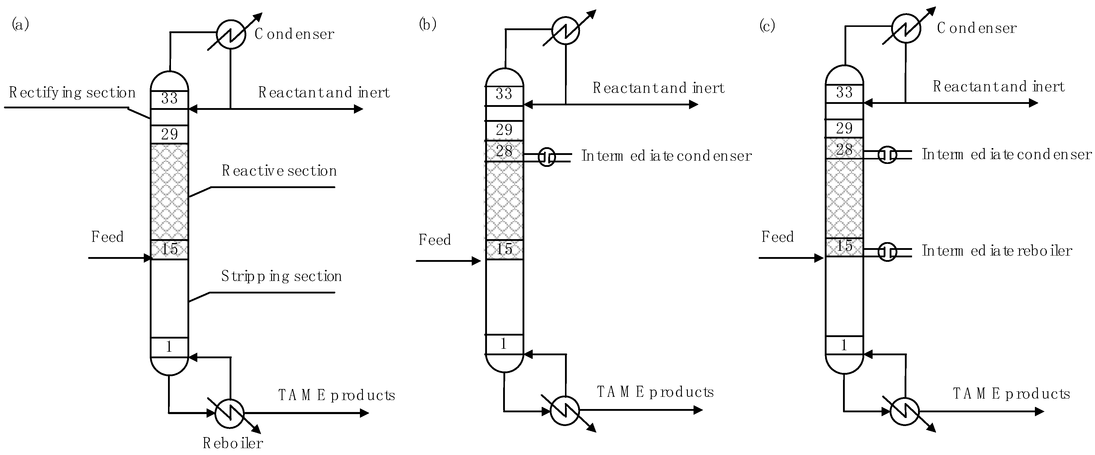
The present work investigated the factors leading to an improvement in the reaction conversion for operation in the multiple steady states. This study focused on the profile of the reactive distillation column used for TAME synthesis. In our previous study, the multiple steady states did not exist for a reflux ratio of 1, but did exist for a reflux ratio of 2. The column profiles of the steady-state solutions for reflux ratios of 1 and 2 were compared. A simulation model of the reactive distillation column with an intermediate condenser at the top of the reactive section was developed to manipulate the internal flow rate of the reactive distillation column. The effect of the intermediate condenser duty on the amount of TAME product and the reboiler duty of the reactive distillation column was clarified. Furthermore, a simulation model of the reactive distillation column with an intermediate condenser and an intermediate reboiler was developed. The effects of the intermediate cooling and heating on the amount of TAME product and the reboiler duty of the reactive distillation were evaluated. Furthermore, the variation in the process performance of the reactive distillation column when the internal vapor liquid flow rate was manipulated was discussed.

2. Simulation Model

2.1. Reaction Kinetics and Physical Properties

The present study focused on TAME synthesis. TAME is produced from 2-methyl-1-butene (2M1B) and 2-methyl-2-butene (2M2B) with methanol (MeOH). The liquid-phase reversible reactions were considered.
2 M 1 B + MeOH TAME
2 M 2 B + MeOH TAME
2 M 1 B 2 M 2 B
The reaction kinetics for TAME synthesis were proposed by several researchers [10,16]. This study used the simple power law model, with the kinetics parameters for the forward and reverse reactions proposed by Al-Arfaj and Luyben [16]. Appendix A presents the reaction kinetics equation and parameters. The Wilson–RK model was used to predict the physical properties of the mixture [7]. The parameters used to predict the physical properties were applied in the Aspen Plus Database of Aspen Plus (Aspen Technology, Inc., Bedford, MA, USA).

2.2. Reactive Distillation Column

Figure 1 shows a schematic diagram of the reactive distillation column examined herein. The reactive distillation column consists of the rectifying, reaction, and stripping sections. TAME was obtained from the bottom-out stream. Table 1 lists the design and operating conditions of the reactive distillation column [15]. A mixture containing the reactant and an inert component was fed to the 15th stage of the column. In this case, to simplify the analysis, the mixture did not contain TAME. Reflux ratio and reboiler duty were used as the operating variables. The reflux ratio was set to either 1 or 2, while the reboiler duty was varied between 6 and 13 MW. Figure 1b presents a schematic diagram of the reactive distillation column with one intermediate condenser. The intermediate condenser was added to the top of the reactive section (i.e., 28th stage). The intermediate condenser duty (Qinter-condenser) was varied between 0 and −5 MW. Figure 1c depicts a schematic diagram of the reactive distillation column with one intermediate condenser and one intermediate reboiler. The intermediate condenser was added to the top of the reactive section (i.e., 28th stage). The intermediate reboiler was added to the bottom of the reactive section (i.e., 15th stage). The intermediate condenser duty was varied between 0 and −5 MW. The intermediate reboiler duty (Qinter-reboiler) was determined as follows:
Qinter-reboiler = −Qinter-condenser.
The present study did not attempt to optimize the locations of the intermediate condenser and reboiler because our objective was to clarify the factors leading to an improvement in the reaction conversion during operation in the multiple steady states. In addition, the energy input to the intermediate condenser and reboiler was defined as shown in Equation (4) to avoid the influence of any deviation in the energy balance on the process characteristics. A model of the reactive distillation column was developed using the RadFrac model in Aspen Plus.

3. Simulation Results and Discussion

3.1. Process Characteristics

Our previous study reported the condition in which multiple steady states exist, as shown in Figure 3 of previous work [15]. For a reflux ratio of 1, multiple steady states did not exist, but were observed at a reflux ratio of 2 for a reboiler duty between 12.25 and 12.12 MW. This study focused on four steady-state solutions. Table 2 summarizes the simulation results for each steady-state solution. Three solutions with reboiler duty values in the middle of the range were selected for the multiple steady states. The MeOH conversion (εMeOH) as the reactant was calculated using the MeOH flow rate in the feed (FMeOH), distillate (DMeOH), and bottom (BMeOH):
ε M e O H = ( F M e O H ( D M e O H + B M e O H ) ) F M e O H .
The MeOH conversions in the steady-state solutions in the multiple steady states became higher than those in steady state 1. This result indicates that the reaction conversion in the multiple steady states can be improved.
This section discusses the factors leading to the reaction conversion improvement in terms of the column profiles. Figure 2, Figure 3, Figure 4 and 
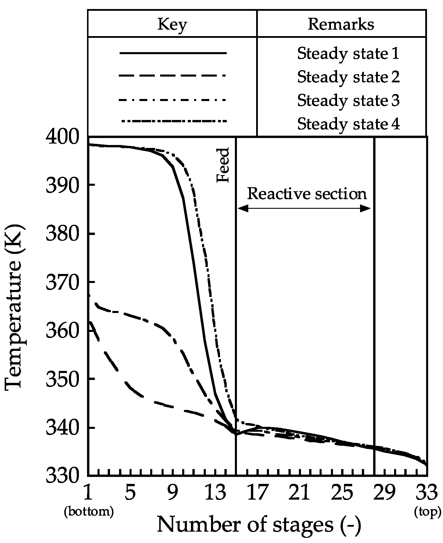
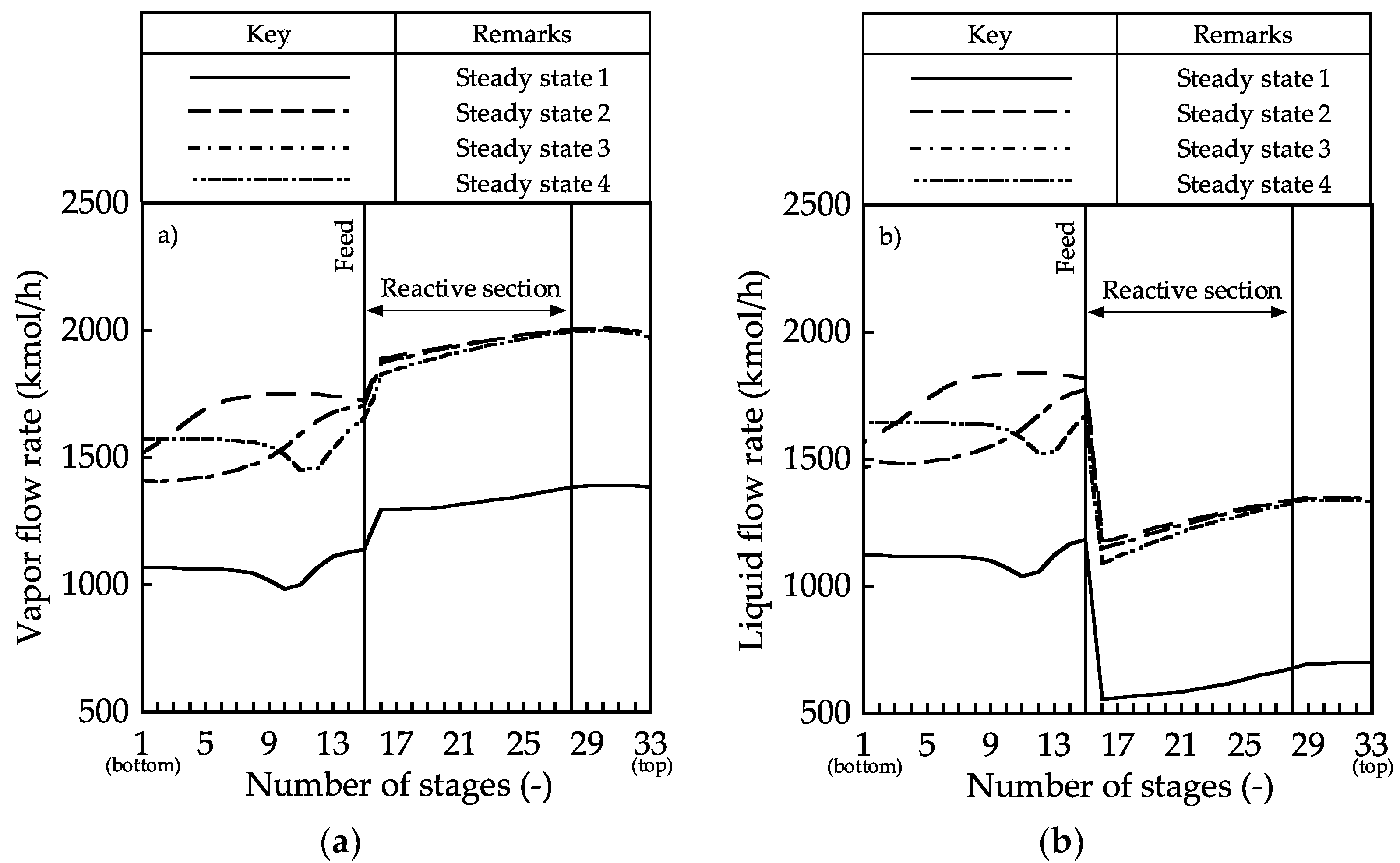
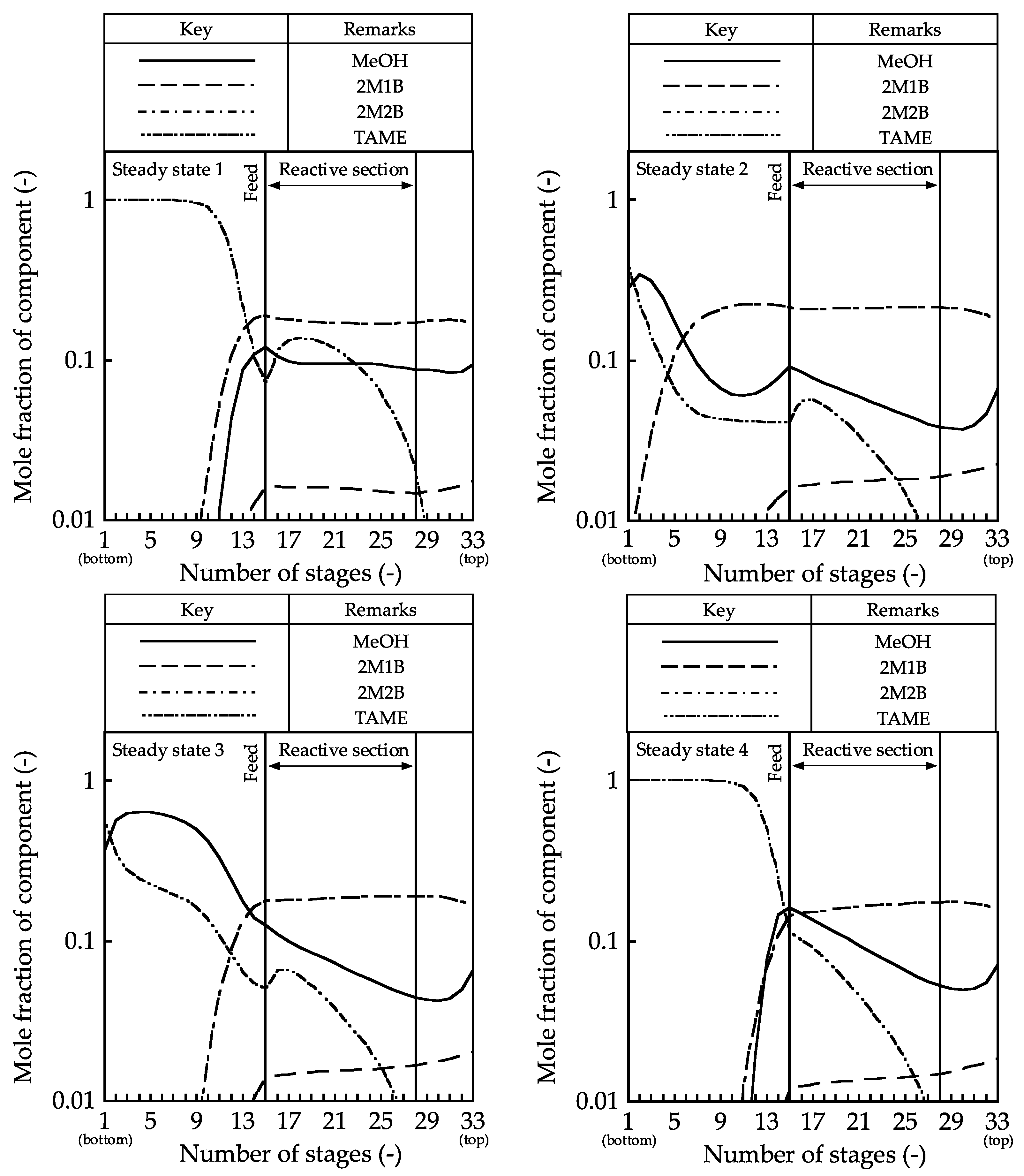
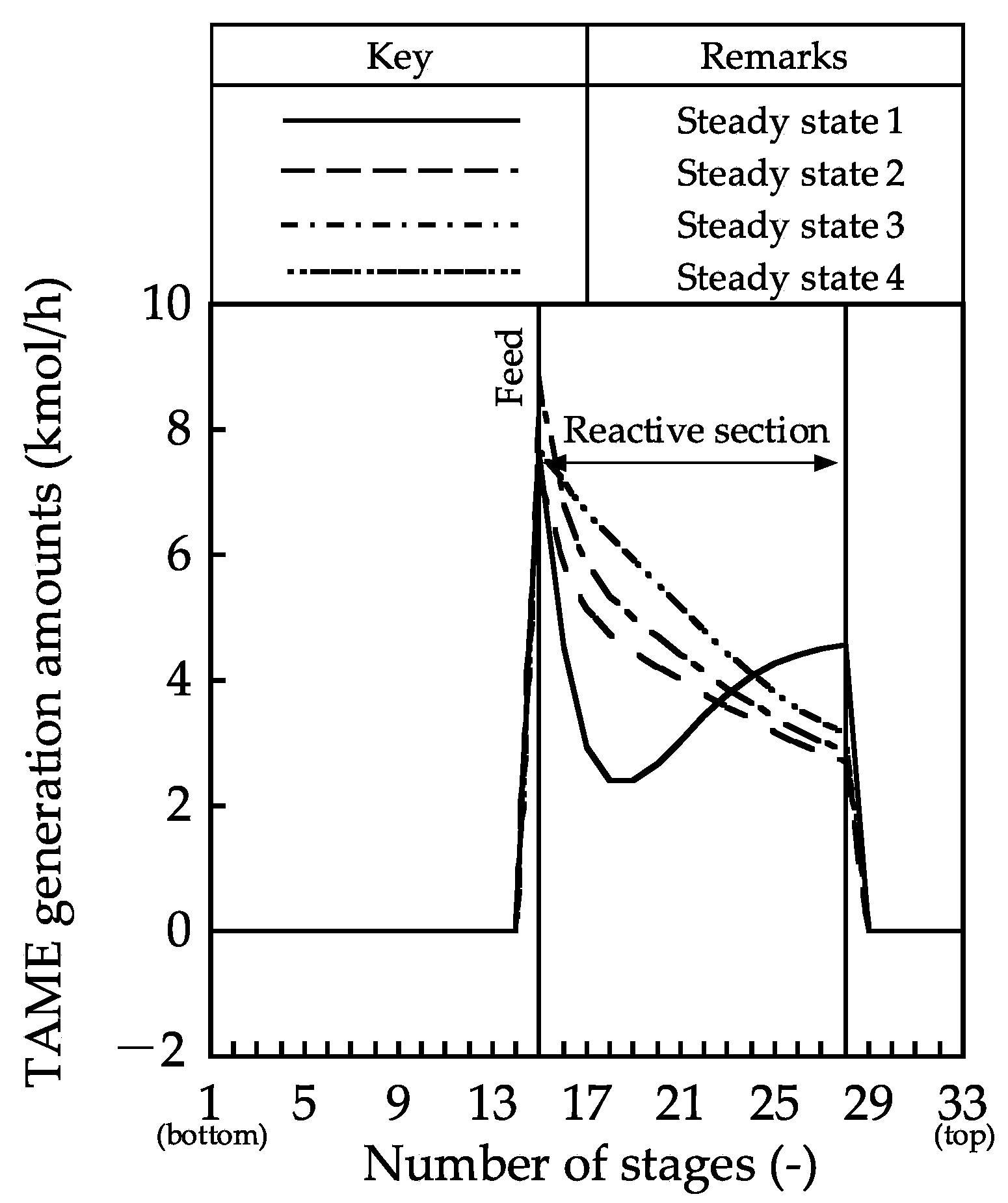
Figure 5 show the column profiles for the temperature, vapor, and liquid flow rates, mole fraction, and generated TAME amounts, respectively. From the temperature profile, in the stripping section, the temperature in the 1st stage for steady states 1 and 4 reached 398.4 K, which is the boiling point of TAME. The TAME and MeOH mixture was obtained as shown in Figure 4; hence, the temperatures in the 1st stage for steady states 2 and 3 were 362.7 and 367.4 K, respectively. However, the temperatures in the reactive sections were nearly the same in each of the four steady states; thus, the temperature in the reactive distillation column has little effect on the MeOH conversion.
The vapor and liquid flow rate profiles showed that the vapor and liquid flow rates in steady states 2–4 were larger than that in steady state 1 because the reflux ratio in steady states 2–4 were higher than that in steady state 1. Large vapor and liquid flow rates promoted separation. Therefore, the vapor–liquid flow rate contributed to an increase in the MeOH conversion.
The composition profiles and the generated TAME amount profile showed little change in the mole fractions of MeOH, 2M1B, and 2M2B in the rectifying and reactive sections in steady state 1. The reactants were distilled from the distillate stream; hence, the generated TAME amounts became small. In contrast, in steady states 2–4, the mole fraction of MeOH in the reactive section decreased along with the stage number because MeOH was consumed by TAME synthesis around the bottom of the reactive section. In the stripping section, TAME was not separated from MeOH, and MeOH was discharged from the bottom stream in steady states 3 and 4. By contrast, high-purity TAME was obtained in steady state 5. For these column profiles, the internal vapor–liquid flow rate must be controlled, and the discharge of reactants must be prevented to increase the reaction conversion.

3.2. Effect of an Intermediate Condenser

Based on the abovementioned results, the small MeOH conversion in steady state 1 was caused by the small internal flow rate and the reactant discharge from the top of the reactive section. The internal flow rate may be increased, such that the MeOH discharge is reduced, by condensing the vapors from the top of the reactive section. Thus, a simulation model of the reactive distillation with an intermediate condenser at the 28th stage (top of the reactive section) was developed (
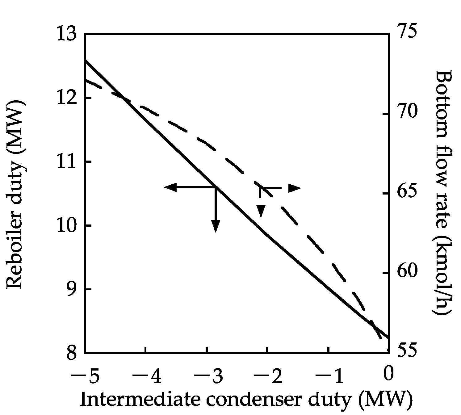
Figure 1b). The effect of the intermediate condenser duty on the column profiles was then evaluated. The intermediate condenser duty was changed from 0 to −5 MW. The reboiler duty was adjusted such that the TAME mole fraction in the bottom stream reached 1.00.
Figure 6 shows the effect of the intermediate condenser duty on the bottom flow rate and reboiler duty. The bottom flow rate increased with an increase in the intermediate condenser duty, indicating that the MeOH conversion increased because the TAME mole fraction in the bottom stream was 1.00. 
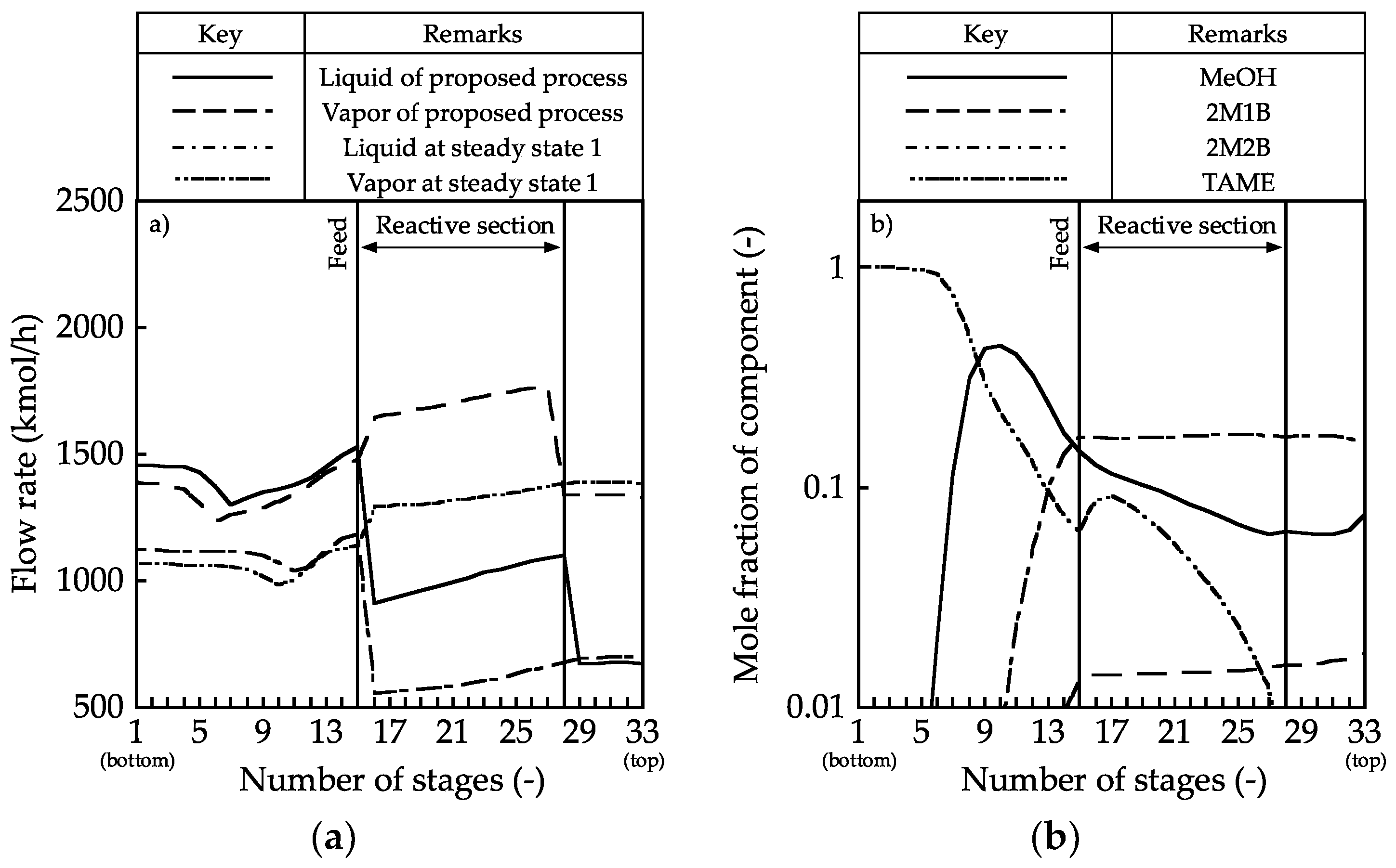
Figure 7 presents the vapor–liquid flow rate and the composition profiles for an intermediate condenser duty of −3.0 MW. In this case, the internal flow rate was larger than that in steady state 1. The composition profile was such that the mole fraction of MeOH decreased along with the stage number in the reactive section, leading to an improvement in the reaction performance. However, in the stripping section, the mole fraction of MeOH was higher than that in steady state 3. The MeOH conversion may increase if the amount of MeOH discharged from the bottom of the reactive section decreases.

3.3. Effects of the Intermediate Condenser and the Intermediate Reboiler

This study also examined liquid vaporization from the bottom of the reactive section with the intermediate reboiler to reduce the amount of MeOH discharged from the bottom of the reactive section. A simulation model for the reactive distillation column with an intermediate reboiler and condenser was developed (Figure 1c).
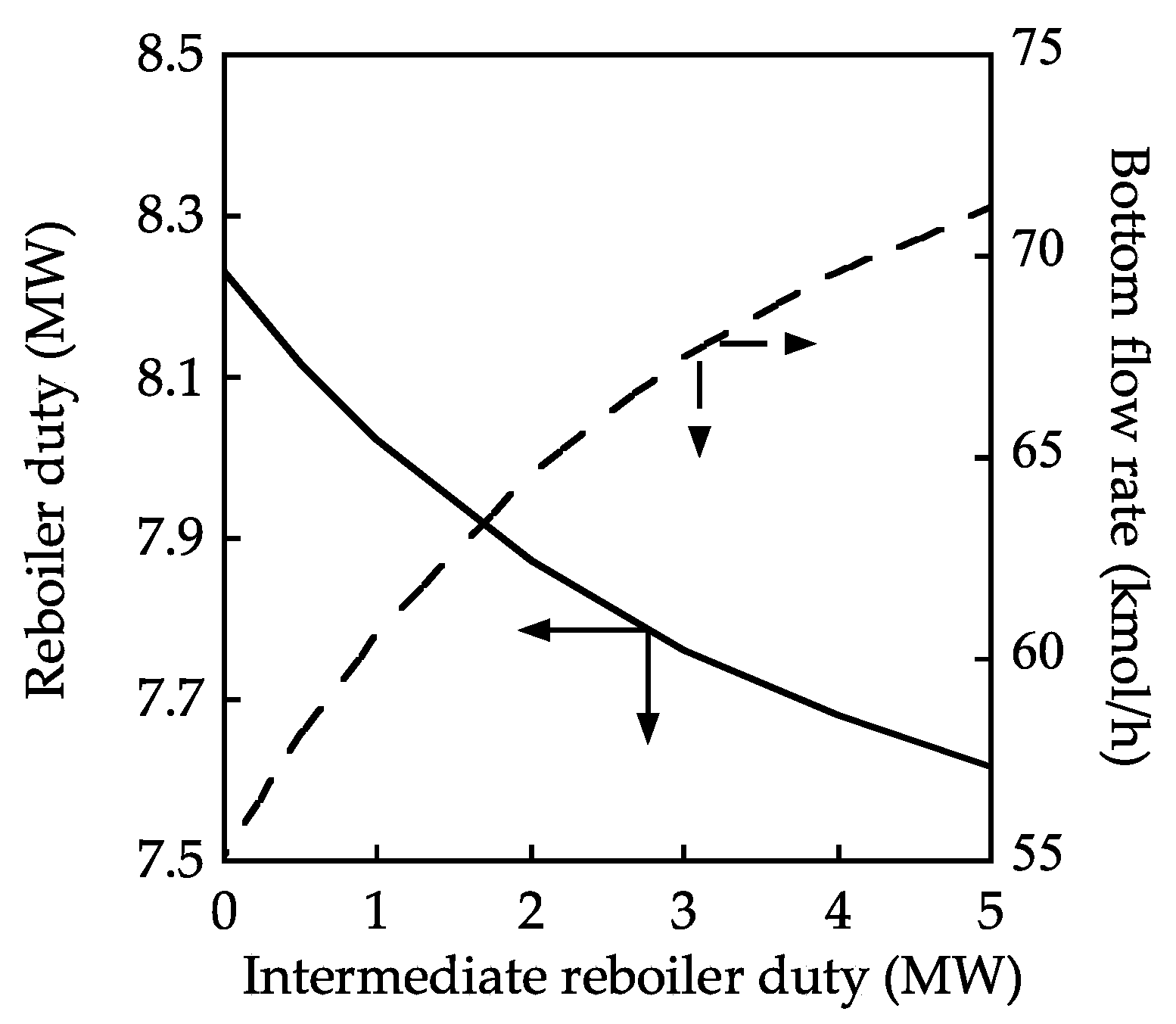
Figure 8 shows the effects of the intermediate condenser and reboiler duty on the bottom flow rate and reboiler duty. The reboiler duty was adjusted such that the TAME mole fraction in the bottom stream reached 1.00. The effect of the intermediate reboiler duty on the bottom flow rate was similar to that in Figure 6. The degree of MeOH conversion also cannot increase beyond the results attained with reactive distillation when using an intermediate condenser. However, the reboiler duty can be reduced with the addition of the intermediate reboiler presumably because the separation of TAME and MeOH occurs as a result of introducing the intermediate reboiler.
Finally, the energy consumption for each reactive distillation column is discussed. A comparison was made with the energy consumption when TAME was produced at a rate of 72 kmol/h from the bottom-out stream. The energy consumptions in steady state 4 of the reactive distillation column with one intermediate condenser and of the reactive distillation column with one intermediate condenser and reboiler were 612, 628, and 637 kJ/mol. The present study did not attempt to optimize either the locations of the intermediate condenser and reboiler or the energy input. Further energy savings could possibly be achieved by optimizing these locations and the input energy.

4. Conclusions

The present study clarified the factors leading to an improvement in the reaction conversion during operation in multiple steady states for the reactive distillation column used for TAME synthesis. The column profiles for reflux ratios of 1 (no multiple steady state) and 2 (multiple steady states) were compared. The comparison of the column profiles for four steady-state solutions clearly showed that the internal vapor and liquid flow rates in the reactive distillation column affected the reaction conversion. An intermediate condenser was introduced at the top of the reactive section to control the liquid flow rate in the reactive distillation column. The effect of the intermediate condenser duty on the TAME production was evaluated, with the amount of TAME product increasing from 55.2 to 72.1 kmol/h as a result of operating the intermediate condenser between 0 and −5 MW. The liquid vaporization from the bottom of the reactive section with the intermediate reboiler was also examined. As a result, the amount of TAME product cannot increase beyond the amounts produced by reactive distillation using an intermediate condenser, but the reboiler duty can be reduced through the addition of the intermediate reboiler. These results indicate that the liquid and vapor flow rates in the reactive distillation column influence the reaction and separation performances, respectively.
In the future, we will investigate the attainment of optimal vapor–liquid flow rates with small input energy. The temperature difference between the top and the bottom of the reactive section was 2.9 K (Figure 2). Heat integration between the intermediate condenser and the intermediate reboiler through the application of the heat-pump technology may be effective [17,18,19].

Author Contributions

Conceptualization and methodology: T.Y. and K.M.; validation: T.Y., D.N.-R., and H.M.; investigation: T.Y. and K.M.; resources: K.M.; writing and original draft preparation: T.Y.; writing, review, and editing: K.M., D.N.-R., and H.M.; and supervision: K.M.

Funding

This research received no external funding.

Conflicts of Interest

The authors declare no conflict of interest.

Appendix A

The following are the reaction kinetics equations and the reaction parameters [16]:
R 1 = A f e E f / R T x 2 M 1 B x M e O H A b e E b / R T x T A M E
R 2 = A f e E f / R T x 2 M 2 B x M e O H A b e E b / R T x T A M E
R 3 = A f e E f / R T x 2 M 1 B A b e E b / R T x 2 M 2 B .
Table A1. Reaction kinetics parameters.
ReactionAfEfAbEb
kmol/(s·kg)kJ/molkmol/(s·kg)kJ/mol
R11.3263 × 10876.10372.3535 × 1011110.5409
R21.3718 × 101198.23021.5414 × 1014124.994
R32.7187 × 101096.52264.2933 × 1010104.196

References

  1. Stankiewicz, A.I.; Moulijn, J.A. Process intensification: Transforming chemical engineering. Chem. Eng. Prog. 2000, 96, 22–34. [Google Scholar]
  2. Cárdenas-Guerra, J.C.; López-Arenas, T.; Lobo-Oehmichen, R.; Pérez-Cisneros, E.S.A. Reactive distillation process for deep hydrodesulfurization of diesel: Multiplicity and operation aspects. Comput. Chem. Eng. 2010, 34, 196–209. [Google Scholar] [CrossRef]
  3. Subawalla, H.; Fair, J.R. Design guidelines for solid-catalyzed reactive distillation systems. Ind. Eng. Chem. Res. 1999, 38, 3696–3709. [Google Scholar] [CrossRef]
  4. Taylor, R.; Krishna, R. Modeling reactive distillation. Chem. Eng. Sci. 2000, 55, 5183–5229. [Google Scholar] [CrossRef]
  5. Huss, R.S.; Chen, M.; Malone, M.F.; Doherty, M.F. Reactive distillation for methyl acetate production. Comput. Chem. Eng. 2003, 27, 1855–1866. [Google Scholar] [CrossRef]
  6. Huang, K.; Wang, S.J. Design and control of a methyl tertiary butyl ether (MTBE) decomposition reactive distillation column. Ind. Chem. Eng. Res. 2007, 46, 2508–2519. [Google Scholar] [CrossRef]
  7. Mohl, K.D.; Kienle, A.; Gilles, E.D.; Rapmund, P.; Sundmacher, K.; Hoffmann, U. Steady-state multiplicities in reactive distillation columns for the production of fuel ethers MTBE and TAME: Theoretical analysis and experimental verification. Chem. Eng. Sci. 1999, 54, 1029–1043. [Google Scholar] [CrossRef]
  8. Jacobs, R.; Krishna, R. Multiple solutions in reactive distillation for methyl tert-butyl ether synthesis. Ind. Eng. Chem. Res. 1993, 32, 1706–1709. [Google Scholar] [CrossRef]
  9. Nijhuis, S.A.; Kerkhof, F.P.J.M.; Mak, A.N.S. Multiple steady states during reactive distillation of methyl tert-butyl ether. Ind. Eng. Chem. Res. 1993, 32, 2762–2774. [Google Scholar] [CrossRef]
  10. Baur, R.; Taylor, R.; Krishna, R. Bifurcation analysis for TAME synthesis in a reactive distillation column: Comparison of pseudo-homogeneous and heterogeneous reaction kinetics models. Chem. Eng. Process. 2003, 42, 211–221. [Google Scholar] [CrossRef]
  11. Wang, J.; Change, Y.; Wang, E.Q.; Li, C.Y. Bifurcation analysis for MTBE synthesis in a suspension catalytic distillation column. Comput. Chem. Eng. 2008, 32, 1316–1324. [Google Scholar] [CrossRef]
  12. Ramzan, N.; Faheem, M.; Gani, R.; Witt, W. Multiple steady states detection in a packed-bed reactive distillation column using bifurcation analysis. Comput. Chem. Eng. 2010, 34, 460–466. [Google Scholar] [CrossRef]
  13. Jairne-Leal, J.E.; Bonilla-Petriciolet, A.; Segovia-Hernandez, J.G.; Hernandez, S.; Hernandez-Escoto, H. On the multiple solution of reactive distillation column for production of fuel ethers. Chem. Eng. Process. 2013, 72, 31–41. [Google Scholar] [CrossRef]
  14. Yamaki, T.; Shishido, M.; Matsuda, K.; Matsumoto, H. Effect of operating conditions on the multiple steady states in reactive distillation. Kagaku Kogaku Ronbunshu 2014, 40, 244–249. [Google Scholar] [CrossRef]
  15. Yamaki, T.; Matsuda, K.; Duangkamol, N.R.; Matsumoto, H. Energy-saving performance of reactive distillation process for TAME synthesis through multiple steady state condition. Chem. Eng. Process. 2018, 130, 101–109. [Google Scholar] [CrossRef]
  16. Al-Arfaj, M.A.; Luyben, W.L. Plantwide control for TAME production using reactive distillation. AIChE J. 2004, 50, 1462–1473. [Google Scholar] [CrossRef]
  17. Kansha, Y.; Tsuru, N.; Fushimi, C.; Tsutsumi, A. Integrated process module for distillation processes based on self-heat recuperation technology. J. Chem. Eng. Jpn. 2010, 43, 502–507. [Google Scholar] [CrossRef]
  18. Kiss, A.A.; Landaeta, S.J.F.; Ferreira, C.A.I. Towards energy efficient distillation technologies—Making the right choice. Energy 2012, 47, 531–542. [Google Scholar] [CrossRef]
  19. Matsuda, K.; Iwakabe, K.; Nakaiwa, M. Recent advances in internally heat-integrated distillation columns (HIDiC) for sustainable development. J. Chem. Eng. Jpn. 2012, 45, 363–372. [Google Scholar] [CrossRef]
Figure 1. Schematic diagrams of the reactive distillation columns for TAME (tert-amyl methyl ether) synthesis: (a) conventional, (b) added one intermediate condenser, and (c) added one intermediate condenser and one intermediate reboiler.
Processes 06 00241 g001
Figure 2. Temperature profiles in the reactive distillation column.
Processes 06 00241 g002
Figure 3. Internal flow rate profiles in the reactive distillation column: (a) vapor and (b) liquid.
Processes 06 00241 g003
Figure 4. Composition profiles in the reactive distillation column.
Processes 06 00241 g004
Figure 5. TAME-generated amount profiles in the reactive distillation column.
Processes 06 00241 g005
Figure 6. Effect of the intermediate condenser duty on the reboiler duty and bottom flow rate.
Processes 06 00241 g006
Figure 7. Column profiles in the reactive distillation column with one intermediate condenser: (a) vapor and liquid flow rate and (b) composition.
Processes 06 00241 g007
Figure 8. Effect of the intermediate reboiler duty on the reboiler duty and bottom flow rate.
Processes 06 00241 g008
Table 1. Input parameters for the steady-state simulation model of the reactive distillation column.
Design conditions
Number of stages33stages
Number of rectifying stages5stages
Number of reactive stages14stages
Number of stripping stages14stages
Feed location15thstage
Amount of catalyst1100kg
Bulk density of catalyst900kg/m3
Operating conditions
Pressure of the top253kPa
Pressure drop of stage1kPa
Reflux ratio1, 2-
Reboiler dutyVariableMW
Feed conditions
Flow rate800kmol/h
Pressure280kPa
Temperature332K
Mole fraction
 2-Methyl-butane0.384-
 1-Pentane0.029-
 2-Methyl-1-butane0.022-
n-Pentane0.068-
cis-2-Pentene0.124-
 2-Methyl-2-butene0.196-
 Methanol0.177-
Table 2. Simulation results at various steady-state solutions.
Steady StateInput VariablesOutput Variables
Reflux Ratio (-)Reboiler Duty (MW)xB,TAME (-)Distillate Flow Rate (kmol/h)Bottom Flow Rate (kmol/h)MeOH Conversion (%)
11.008.251.00690.654.6838.7
22.0012.190.67655.386.6941.1
32.0012.190.86659.075.8746.1
42.0012.191.00656.771.6450.7

