1. Introduction
Human activities have played a significant role in the alteration of the climate and the resultant impacts of global warming, primarily due to the emission of greenhouse gases. In 2018, global carbon dioxide (CO
2) emissions, the primary contributors to these changes, amounted to 33.1 gigatons [
1,
2]. Of this total, coal-fired power plants (CFPPs) were responsible for 30%, highlighting their substantial contribution to overall emissions [
3]. This has led to a notable rise in the concentration of atmospheric CO
2. Presently, there are various approaches to diminishing global CO
2 emissions. These strategies encompass the adoption of low-carbon energy sources as substitutes, enhancing energy efficiency at the origin, instituting a carbon tax, afforestation efforts, the preservation of existing forests and grasslands, and the capture of CO
2 from power plants and other carbon-emitting sources [
4,
5,
6]. The global energy landscape is undergoing a significant transformation, emphasizing the need for sustainable and environmentally friendly power generation. As per one study, transitioning hard-to-abate transport sectors to hydrogen reduces transport emissions but increases emissions in other sectors, requiring significant land use for energy crops and posing challenges in water and fertilizer demand. Limited reliance on carbon dioxide removal leads to reductions in energy consumption, emissions, land expansion, water, and fertilizer usage compared to scenarios with unlimited carbon dioxide removal [
7].
The electricity produced from the combustion of fossil fuels such as coal, natural gas, etc. produces a significant amount of carbon dioxide (CO
2). Hence, the power plants operated with natural gas as the main fuel also produce an enormous amount of CO
2 [
8]. The integration of carbon capture technologies with Natural Gas Combined Cycle (NGCC) power plants presents a promising avenue to mitigate the issues of global warming with a reduction in greenhouse gas emissions. Shifting from coal to natural gas can lead to a decrease in CO
2 emissions. Integrating CO
2 capture into NGCC power units is crucial to the ongoing energy transition. This integration is identified as essential for upholding energy security while achieving net-zero emissions [
9]. Bravo et al., (2020) [
8] developed a model for an NGCC plant with post-combustion carbon capture (PCC) in Aspen Plus, validated it, and adjusted it for conditions in Poza Rica, Mexico. Heat integration options were explored, using a flue gas cooler and CO
2 compressor heat for feeding water or LP steam. There are several techniques that could be utilized. Now, carbon capture, utilization, and storage (CCUS) is widely recognized for its substantial potential to align with global climate change objectives while permitting the continued utilization of fossil fuels [
10,
11]. It represents a potentially unparalleled, cost-effective, and scalable approach for decarbonizing industries characterized by high carbon emissions during production [
2]. Various technological pathways exist for CCUS, with PCC standing out as a more mature and readily retrofittable technology when compared to alternatives such as pre-combustion capture and oxy-fuel combustion [
2,
12,
13]. Till now, several carbon capture methods have been developed, which include membrane [
14], absorption-desorption based on solvent utilization [
15,
16], mineralization [
17], and adsorption [
18]. Notably, carbon capture technology using different solvents has reached an advanced stage of development, emerging as the ‘best available technology’, Solvent-based post-combustion carbon capture (PCC) represents one of several choices available for extracting CO
2 from the emissions of power plants [
13]. The processes of chemical absorption of carbon using aqueous amine-based solvents have gained widespread utilization in various industries, primarily attributable to their ability to achieve a higher rate of CO
2 absorption, particularly under conditions characterized by low gas partial pressure. This enhanced capability makes these processes particularly advantageous in industrial settings where efficient and effective carbon dioxide capture is imperative for environmental and operational considerations [
19]. Allangawi et al. [
15] reviewed recent advancements in carbon capture using various physical and chemical sorbents, such as blended absorbents, amine-based sorbents, MOF adsorbents, ionic liquids, zeolites, and more. Among these, amine-based sorbents stand out due to their high multifunctionality, stability, enhanced sorption capacities, and rapid capture. Su et al. [
13] conducted a series of modeling activities, focusing on three representative configurations of Waste-to-Energy (WtE) plant steam cycles. These configurations were chosen to incorporate post-combustion CO
2 capture (PCC) using monoethanolamine (MEA). Viola et al. [
20] studied the CO
2 capture on silica impregnated with amine. However, the regeneration of CO-rich amine solutions is cost-intensive due to energy consumption, accounting for approximately 70% of the cost of operation [
21,
22]. Addressing the cost remains a crucial challenge that requires further research and development.
Over the past few decades, solar-assisted PCC has gained significant attention [
8], which has the potential to offset the high operating costs associated with CO
2 capture and solvent regeneration. This technology fulfills its energy demands in the form of reboiler duty through the utilization of solar energy. Kev, Modi [
23] assessed the life cycle of three carbon capture methods: conventional PCC, solar-assisted PCC, and a unique solar-powered PCC with independent solvent regeneration in the solar collector field. The solar-powered PCC exhibited the lowest levelized global warming potential (865 kgCO
2-eq/MWh), resulting in the highest CO
2 abatement relative to the base case (18.1% for a 660 MWe plant and 38.1% for a 330 MW
e plant).
Parabolic trough solar collectors are a well-established technology for harnessing solar energy. They consist of curved, reflective troughs that concentrate sunlight onto a focal line where a receiver tube is positioned. This receiver tube contains a heat transfer fluid, typically oil or molten salt, which absorbs the concentrated sunlight and reaches high temperatures. The heated fluid is then used to generate steam, which drives a turbine to produce electricity in concentrated solar power (CSP) plants. Parabolic trough collectors offer high efficiency and scalability, making them suitable for utility-scale power generation as well as industrial process heat applications. With decades of proven performance, parabolic trough technology continues to play a significant role in the transition to clean and sustainable energy sources. Several commercial parabolic solar collectors are available, among which a few are highlighted in
Table 1.
Wang et al. [
24] constructed a pilot system of solar thermal energy-assisted chemical absorption to examine system performance, utilizing parabolic troughs and linear Fresnel reflector collectors. Operation parameters met design requirements, and solar collectors supplied thermal energy for the reboiler, dependent on solar irradiation. Wang et al. [
25] through the experimental facility with parabolic troughs and linear Fresnel collectors to understand the solar-assisted post-combustion carbon capture system to counteract coal-fired plant energy penalties from absorbent regeneration. Dynamic performance was affected by parameter variations and solar collector fluctuations. Mokhtar et al. [
26] proposed a solar-assisted post-combustion carbon capture (SPCC) system to reduce the output power penalty (OPP) in fossil-fuel power plants. The system aimed to use solar thermal energy for part of the PCC energy input, potentially aligning with peak electricity prices. Li et al. [
27] examined solar-assisted post-combustion CO
2 capture (SCC) in an amine-based power plant. Local conditions strongly impacted SCC performance, influencing costs. Cohen [
28] reviewed solar thermal technologies for CO
2 capture, identifying parabolic troughs and central receivers as technically feasible. Multiple studies have explored solar-assisted PCC as a solution for mitigating the energy penalty in fossil-fuel power plants.
Ampah et al. [
29] employed the Global Change Assessment Model for carbon dioxide removal (GCAM-CDR) to model five CDR approaches within four deployment plans for China’s climate goals. Results suggested that focusing solely on land-based biological CDR methods could lead to notable reductions in fossil fuel consumption, greenhouse gas emissions, and air pollutants, highlighting diverse implications for China’s carbon neutrality aspirations.
In the context of previous research efforts, the present study seeks to significantly advance the integration of solar thermal energy into the Besmaya NGCC plant in Baghdad, Iraq. While past studies may have explored aspects of solar energy integration or power plant simulations individually, this work uniquely combines these elements through comprehensive process simulation and modelling using Aspen Plus V 11 software. The core objective of current studies lies in not only simulating the power plant under its existing conditions but also conducting a thorough preliminary analysis. Furthermore, prior studies are extended in current research by simulating and integrating a solar-assisted PCC plant into the current power setup, presenting a novel approach to enhancing energy efficiency and sustainability. Importantly, the entire process is evaluated in detail, providing a comprehensive technical assessment. Additionally, this study contributes new insights by estimating the solar thermal power potential specifically tailored to the Baghdad coordinates, leveraging the capabilities of SAM. Through these advancements, it is aimed at addressing existing gaps in the literature and offering valuable insights for future research and practical applications in the field of renewable energy integration within conventional power plants.
2. Development of the Combined Cycle Power Plant (CCPP) Model with PCC
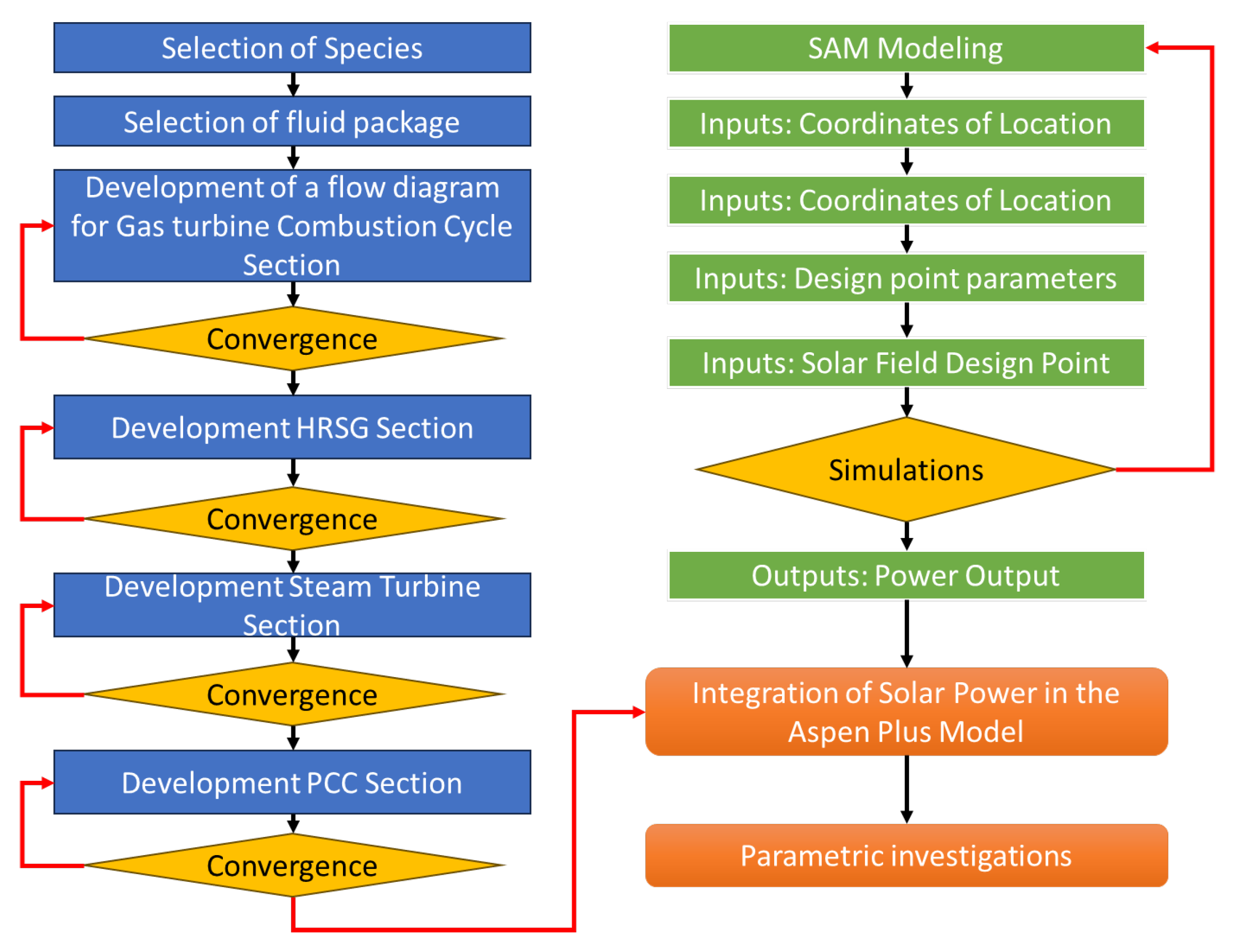
The Besmaya Natural Gas Combined Cycle (NGCC) power plant stands as Iraq’s most significant power generation facility, boasting an impressive installed capacity of 3 GW. Situated just 25 km east of Baghdad, outside the Kurdistan region, this pivotal energy infrastructure plays a crucial role in meeting the nation’s power demands. To gain insights into its operational dynamics, a comprehensive simulation of the Besmaya NGCC was conducted using the widely recognized Aspen Plus modeling tool. The overall methodology of the research is shown in
Figure 1.
For the basis of this study, essential design information was sourced from a detailed report provided by General Electric (GE) on Steam Turbine Operations Mass Global Investment, specifically focusing on the Besmaya Combined Cycle Power Plant (CCPP) located in Baghdad, Iraq [
30]. The Aspen Plus simulation software was used to develop the model of the NGCC plant, adhering to the plant configuration and performance parameters outlined in the GE report.
Dividing the NGCC plant into four primary sections, each of these segments plays a distinctive role in the overall operational efficiency. The Plant Combined Cycle (PCC) configuration, as specified by the GE report, served as the blueprint for constructing the Aspen Plus simulation model. The ensuing sections delve into a comprehensive discussion of each of these constituent parts, shedding light on their functionalities within the overarching NGCC plant framework. This approach allows for a detailed examination of the plant’s inner workings and facilitates a thorough understanding of its complex system dynamics.
The Peng-Robinson equation of state (Equation (1)) was used, as it is the recommended thermodynamic property package for power plants and hydrocarbon systems [
31]. A variety of unit operations available in the software were utilized to develop the model. All the utilized operations are described in
Table 2.
As per usual practice, modeling requires assumptions. For the current studies, the following assumptions were made to develop a comprehensive and representative model:
It was assumed that the physical properties of materials and fluids within Aspen Plus were accurately represented. Moreover, Aspen Plus library components and models that were utilized for simulating NGCC plant components are estimating the real parameters.
Custom models or Aspen Plus extensions were implemented for simulating solar thermal energy integration.
The steady-state operating conditions were maintained for NGCC and solar components.
The climate data specific to the Baghdad region was used for solar resource assessment using SAM.
The model validation is conducted through comparison with available plant data or experimental results.
It was assumed that sensitivity analysis is performed to assess uncertainties and identify key parameters affecting system performance.
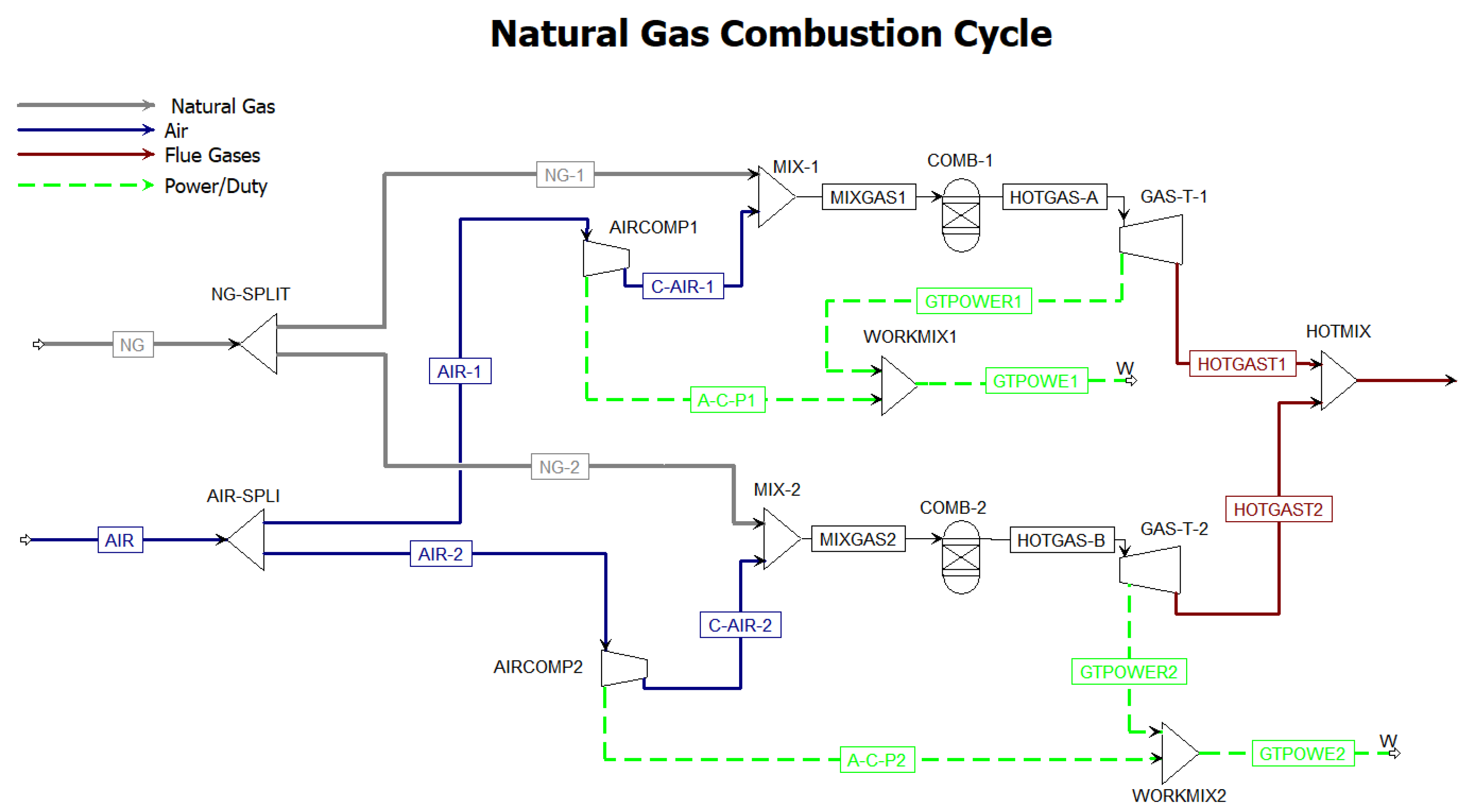
2.1. Gas Turbines Section
The NGCC plant design is based on the natural gas combustion system (
Figure 2). It consists of two gas turbines with a 260 MW capacity, each with 98% mechanical efficiency. Twenty percent of the excess air is compressed to attain 20 bar pressure before feeding into the combustion chamber. For the combustion chamber, the RGibbs reactor model was used in the Aspen Plus simulation software, which is based on the principle of minimizing Gibbs free energy. This involves solving equations that describe the system’s behavior while minimizing the free energy of the system under given constraints, such as temperature, pressure, and composition. The existing plant conditions are tabulated in
Table 3, which was taken from the plant manual [
30].
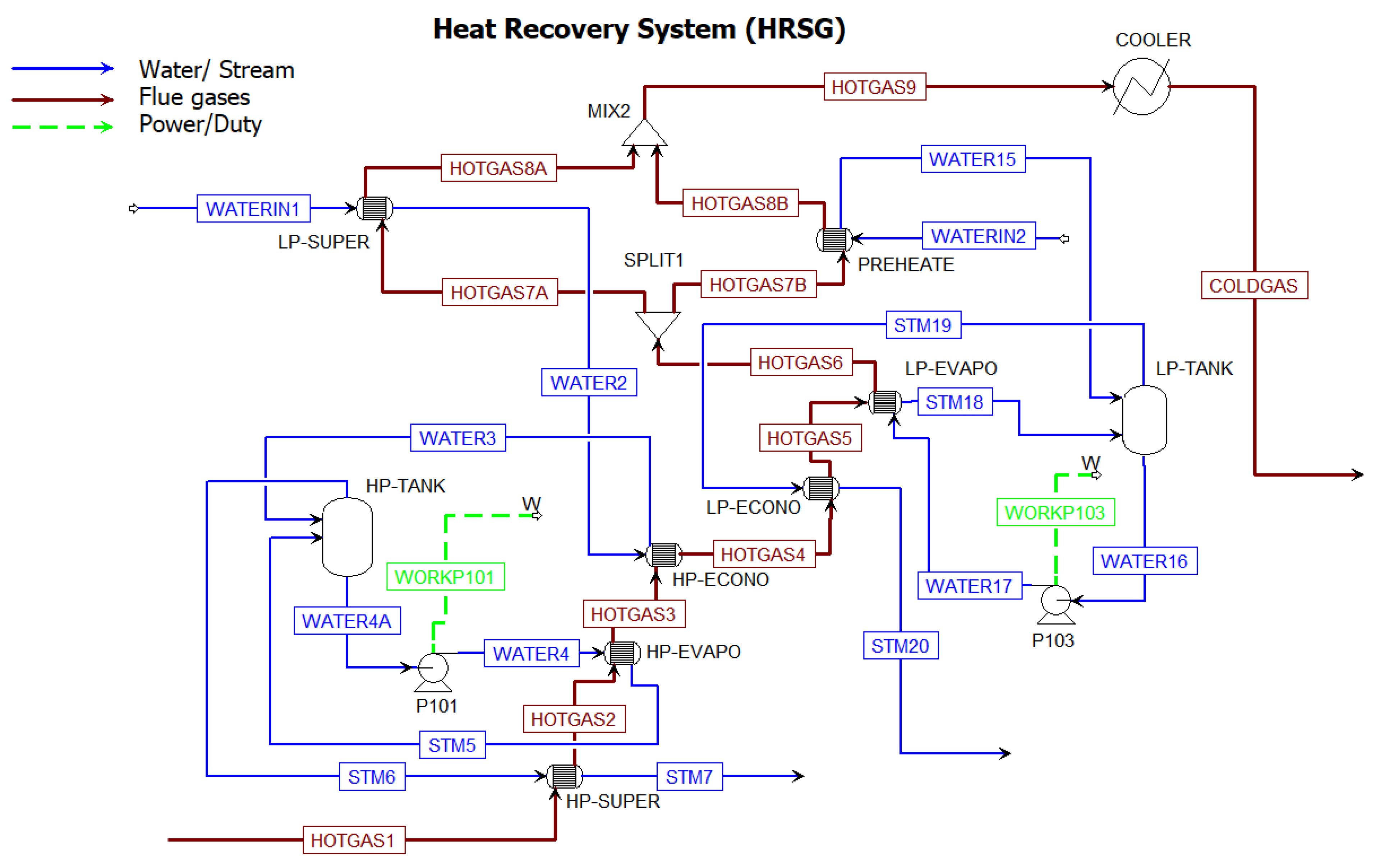
2.2. Waste Heat Recovery and Steam Generation Section
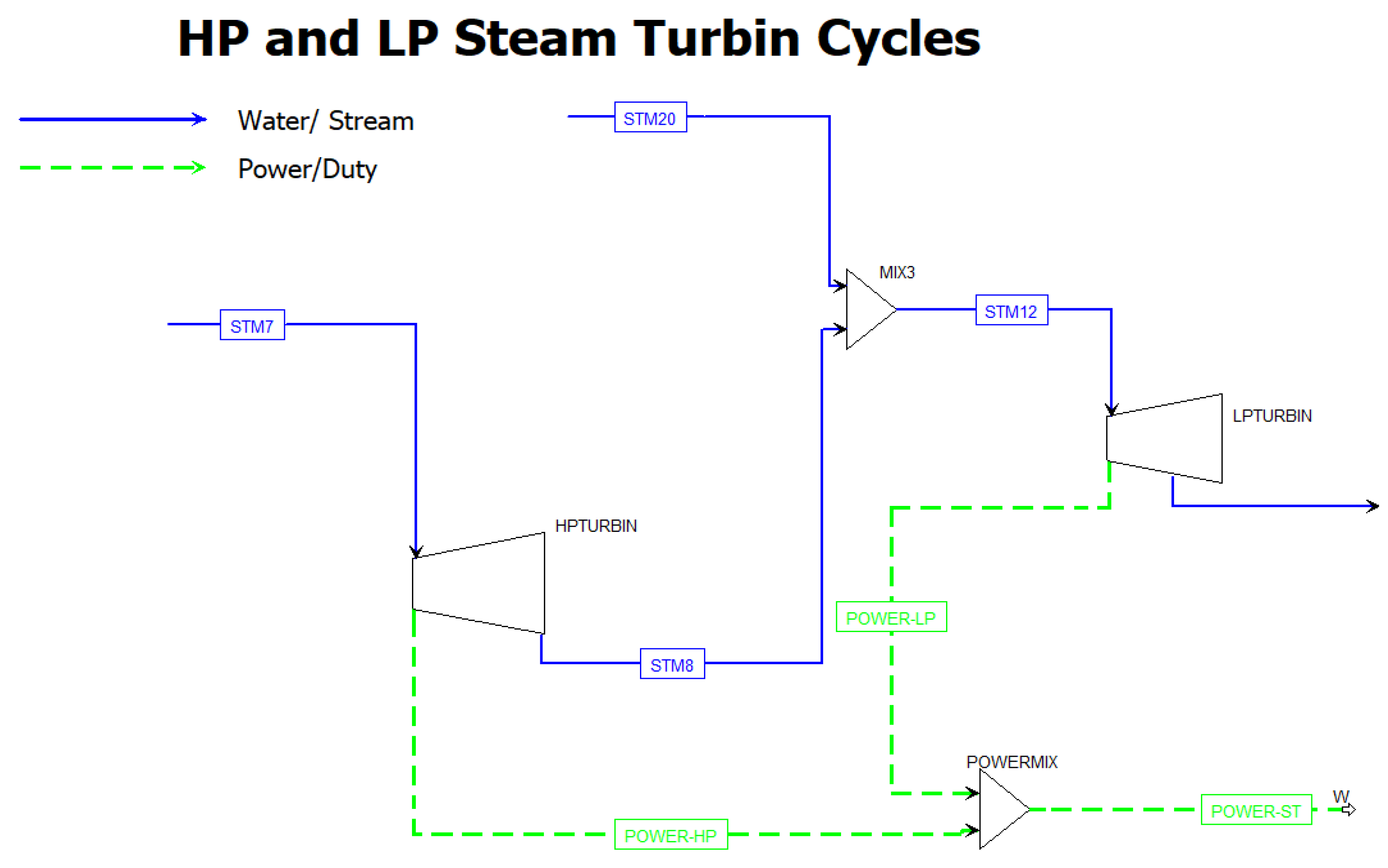
After the natural gas combustion in the gas turbine system, the hot gases produced in the temperature range of 600–650 °C are sent to the heat recovery steam generator (HRSG) system. In actuality, there are two separate HRSGs in the plant. However, for the sake of simplicity, the two separate streams of hot flue gases are merged into a single stream and fed to the HRSG system. The HRSG supplies heat to a single steam turbine generator (STG) cycle, as shown in
Figure 3. The HRSG contains high-pressure (HP) and low-pressure (LP) sections, with independent economizer, evaporator, and superheater heat exchangers for each pressure level. The water is fed into the HRSG system via two water streams. One water stream is passed from the LP-superheater and HP-economizer, converted into saturated steam, and fed into the HP-tank. The circulation of condensate from the HP-evaporator is maintained via a pump with 85% efficiency. The HP steam from the HP tank is finally passed from the HP-super heater to reach a temperature of 530 °C, and a pressure of 73 bar is ready to generate power from the HP-steam turbine (
Figure 4). LP steam is generated from the LP-economizer at a pressure of 6 bar and a temperature of 156 °C, mixed with the LP steam coming from the HP-steam turbine, and fed into the LP-steam turbine. Both turbines cumulatively produce 230 MW of power. In this way, the total power production of the whole plant is in the range of 750 MW.
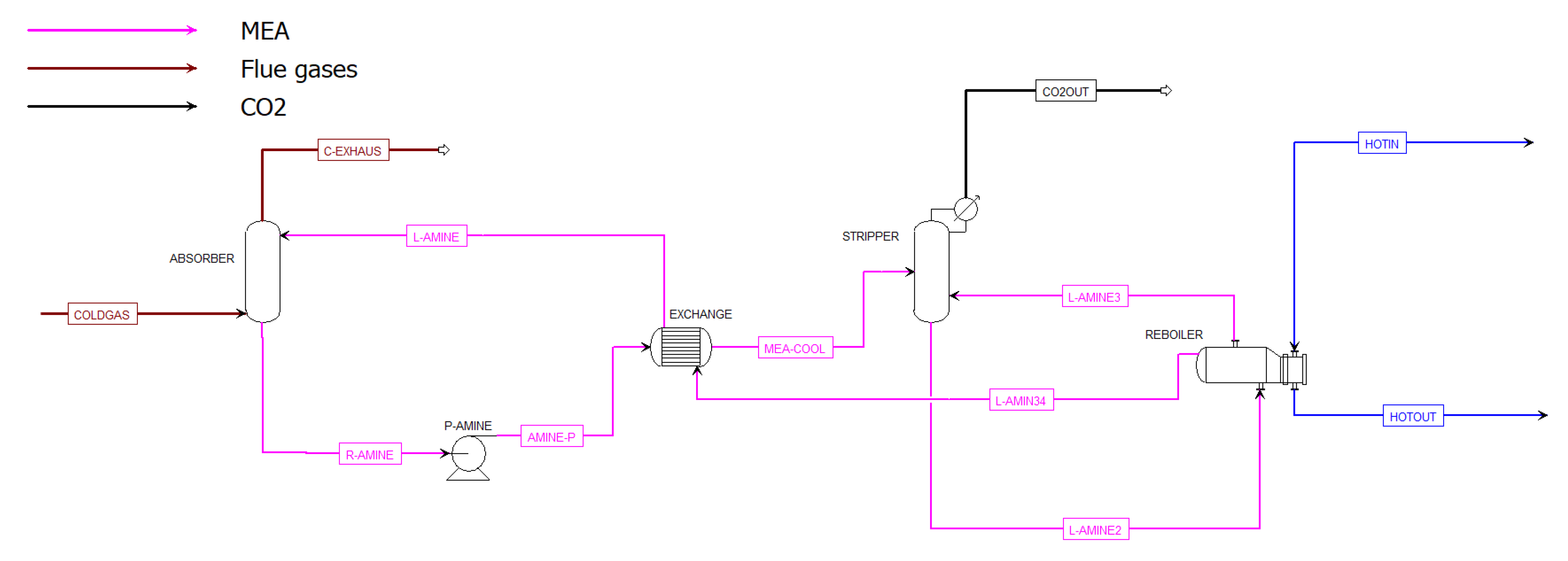
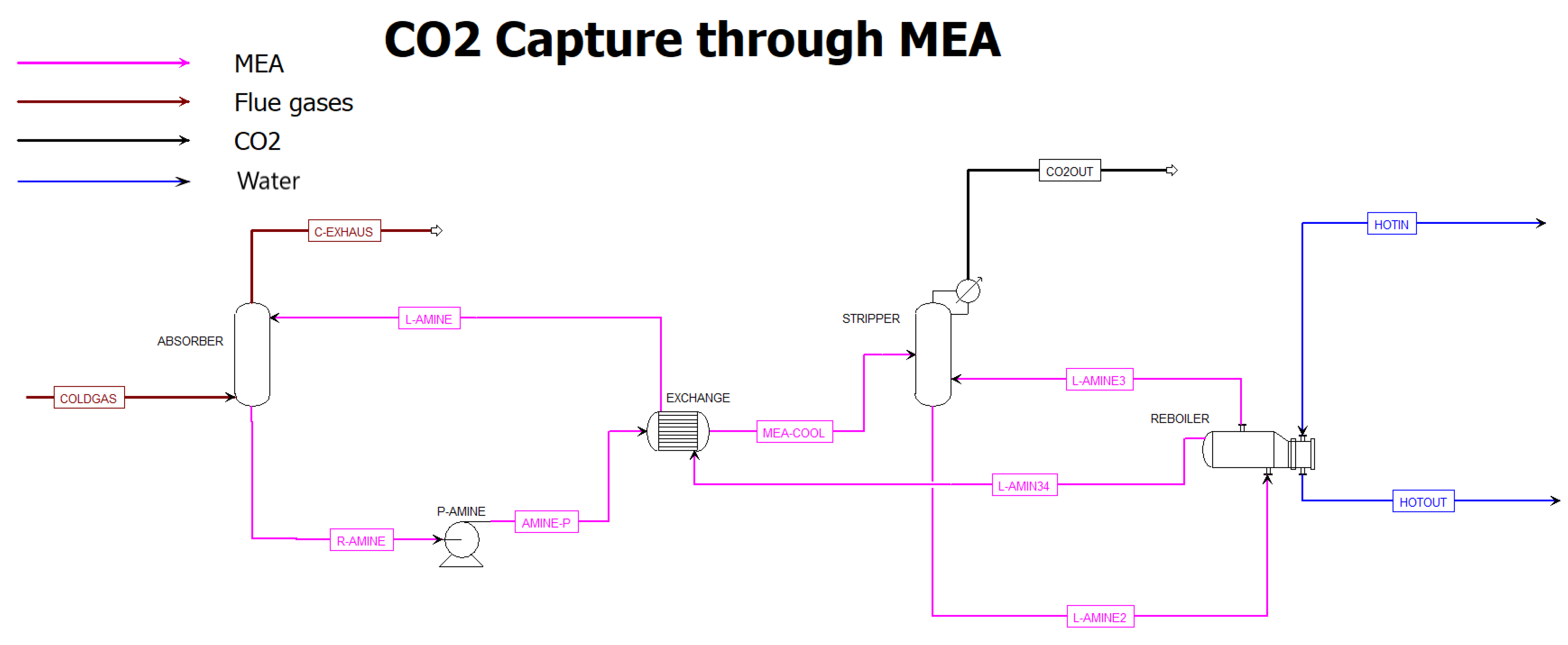
2.3. CO2 Capture Plant
In the subsequent phase, the addition of a post-carbon capture (PCC) process based on monoethanolamine (MEA) absorbent was considered, achieving the capture of CO
2 from the flue gases coming out of the HRSG section. MEA is considered an economic and efficient absorbent for capturing CO
2 from exhaust gases [
32]. The PCC system employing MEA comprises a low-temperature absorber column (refer to
Figure 5), where carbon dioxide is absorbed efficiently and effectively from flue gas through CO
2-lean MEA. Following partial heating in a heat exchanger (crossflow) by the high-temperature CO
2-lean MEA exiting the stripper, the CO
2-rich MEA proceeds to a stripper column, where thermal stripping of carbon dioxide from the amine takes place. The reboiler provides heat to the stripper through LP steam, and the CO
2 separated from the MEA is released at the upper section of the stripper. The generation of the LP steam (Hot In stream) is facilitated by concentrated solar power (CSP).
2.4. Integration of Solar Heat for PCC
PCC requires heat in the reboiler (
Figure 5) for stripping off the CO
2 from the rich amine for its recirculation. This energy requirement for heating purposes can reduce the overall economy of the PCC process. Utilization of solar energy for heating the reboiler through heat transfer fluid (HTF) is an option already discussed by researchers [
8,
26,
33]. For this purpose, an HTF circulation loop for adjusting reboiler heat was integrated into the developed NGCC + PCC model.
Initiating the assessment of the Solar-Assisted Combined Cycle (SACC) involved a meticulous simulation to gauge the implications of incorporating a solar thermal resource into the pre-existing NGCC + PCC models. The primary utilization of solar thermal energy was identified, focusing on its application in heating the PCC stripper reboiler. This specific application proves to be highly suitable for solar thermal energy integration, primarily due to the relatively moderate steam temperatures required for the stripper, hovering around 170 °C.
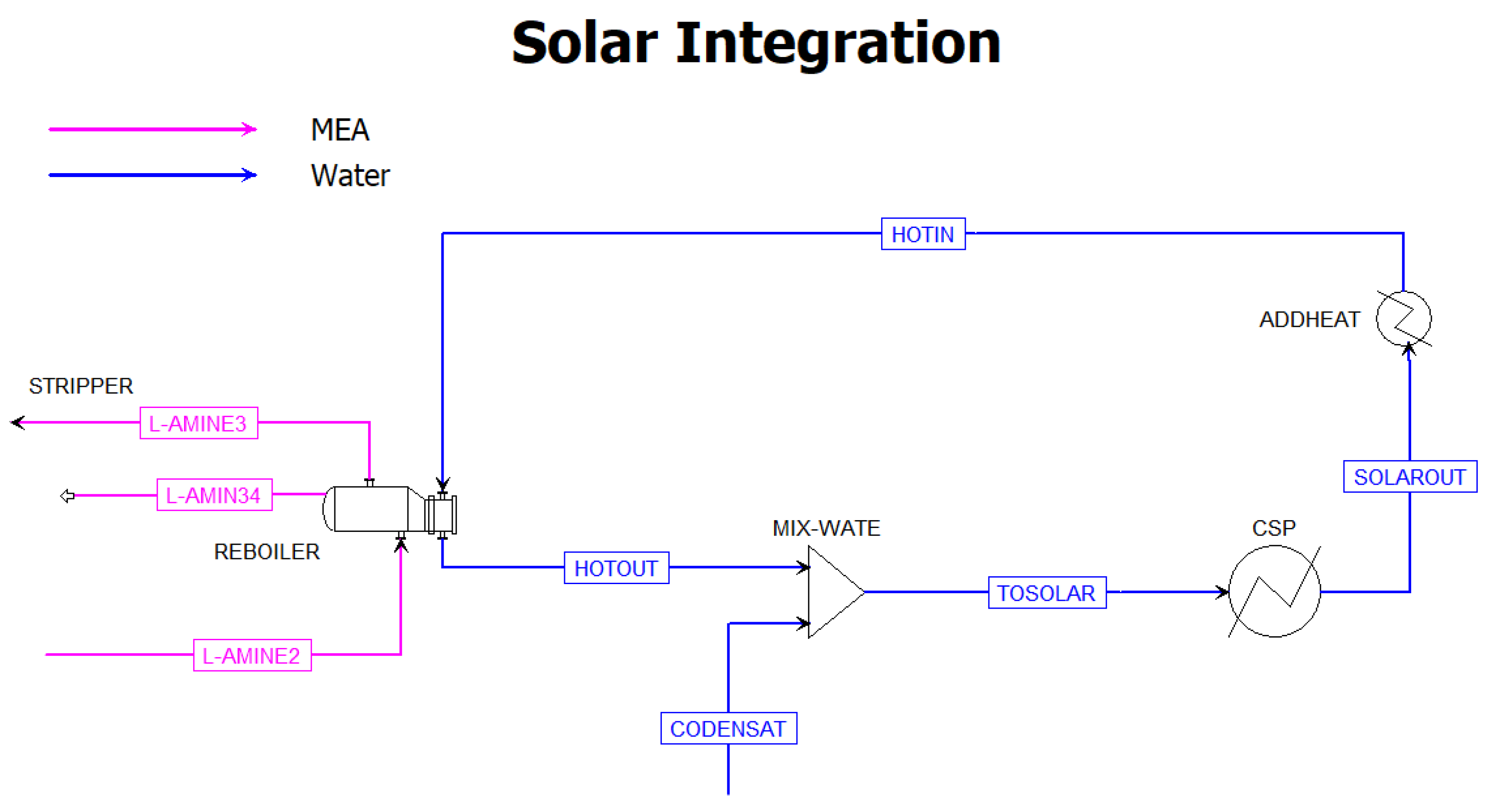
The augmentation of solar energy serves as a direct mechanism for elevating the overall net power output of the plant. This enhancement is achieved by diminishing the reliance on low-pressure (LP) steam extraction for the reboiler. The solar-assisted reboiler heating configuration is elucidated in
Figure 6, offering a visual representation of the innovative setup. Within this framework, a high-temperature Fluid (HTF), in this instance water, with a temperature of 150 °C derived from the solar field, is further heated to 300 °C by an “ADDHEAT” heater (
Figure 6), which then effectively elevates the temperature of LP steam entering the stripper reboiler to 170 °C, strategically positioned at 0.9 °C above the saturation temperature.
Upon imparting thermal energy to the LP steam, the HTF undergoes a controlled heat rejection process, subsequently returning to the solar field at a temperature of 130 °C. The conditioned 170 °C steam enters the reboiler, liberating heat during the crucial phases of condensation and subsequent cooling, ultimately reaching a temperature of 130 °C. This intricate interplay of solar thermal energy integration not only optimizes the efficiency of the NGCC + PCC model but also underscores the potential for harnessing renewable sources to augment conventional power generation processes. The schematic representation in
Figure 5 serves as a valuable visual aid in comprehending the intricate details of this solar-assisted reboiler heating mechanism within the broader context of the power plant’s operation.
2.5. Modeling of the Solar Field with Parabolic trough Collectors
The strategy employed by Bravo et al. (2020) [
8] for harnessing solar energy is being utilized in current research to simulate a parabolic trough collector at a plant in Baghdad, Iraq, using NRELS’s SAM 2022.11.21 r3 Version [
34]. The initial stage of configuring the SAM model involves procuring solar and weather details for the site under consideration. For this study, Baghdad was chosen as the desired location, and corresponding weather data retrieved from a station situated at coordinates 33°18′46.0980″ N and 44°21′41.3568″ E were fed into SAM. SAM calculated that direct normal irradiance (DNI), on average per day for this region, is put up to be about 5 kW h/m
2/day, while July has recorded DNI reaching maximum values around approximating 773 W/m
2, which correlates with peak levels expected during typical days within that month, where DNI peaks are likely nudging roughly around an anticipated value averaging out approximately 770 W/m
2 throughout those specific periods when such figures may occur.
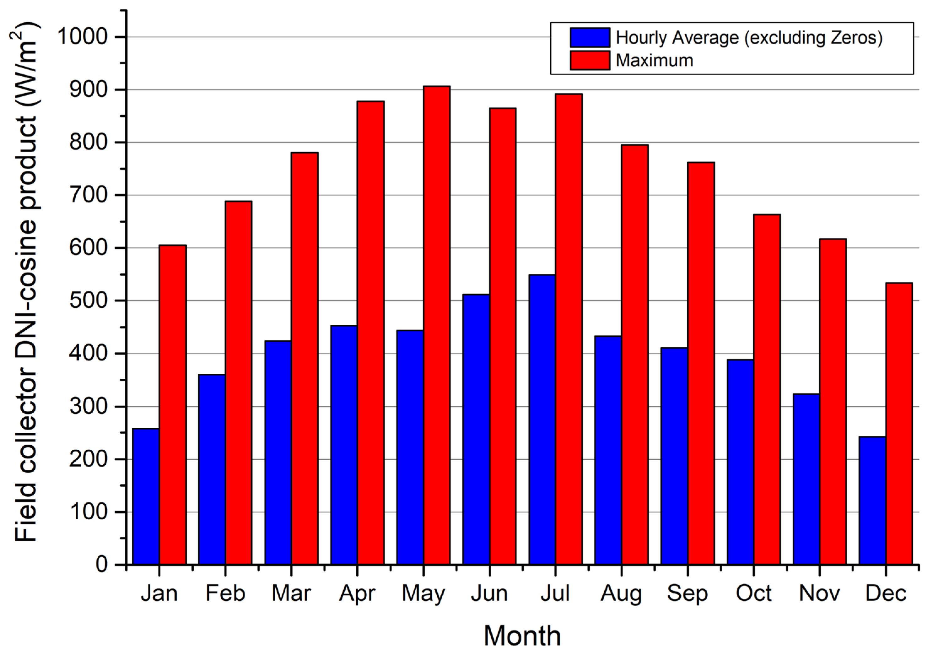
Figure 7 presents the hourly DNI-cosine product irradiance for a parabolic trough collector, which better showcases the actual variability in irradiance. The peak of this product is observed to be just above 900 W/m
2 during hours of intense direct sunlight. Accordingly, SAM was used to design and configure the parabolic trough solar collector field based on this maximum value of irradiance.
Table 4 provides details regarding critical design parameters for constructing and modeling an appropriately configured solar field in Baghdad, Iraq, using available solar-irradiation data.
In formulating the design parameters for the solar thermal power component, a targeted capacity of 350 MW was established. A solar multiple of 1.8 was rigorously defined, with the explicit goal of delivering heat to the thermal heat sink within the solar system through the high-temperature Fluid (HTF). The determination of the thermal duty of this heat sink was rooted in the overall thermal power requirement for the stripper reboiler. Considering the prescribed solar multiple of 1.8, the envisaged power input to the HTF at the receiver stood at 630 MW.
In this solar thermal design, a key aspect is determining the specific temperature at which the high-temperature fluid (HTF) should reach as it exits the system. This temperature is set at 260 °C. This precision is critical to ensuring optimal performance and efficiency of the system. This strategic measure was purposefully instituted to uphold a thermal profile significantly higher than the ultimate thermal sink, as represented by the steam entering the reboiler of the stripper at a temperature of 170 °C. This deliberate choice in temperature control is instrumental in optimizing the overall efficiency and performance of the solar-assisted system within the broader context of the NGCC + PCC power plants.
Furthermore, an additional consideration in the design involved addressing the introduction of cold condensate into the HTF-to-reboiler steam heat exchanger, where the condensate enters at approximately 150 °C. In response to this thermal condition, a judiciously selected return temperature of 160 °C for the HTF as it cycles back to the solar field was meticulously delineated. Choosing the exact temperature for the fluid to return is an important decision. 260 °C is chosen because it helps keep everything working smoothly in the solar-assisted reboiler heating system. This decision ensures that the system stays at the right temperature for efficient operation. The interplay of these temperature controls demonstrates the intricacy and foresightedness embedded in the design of the solar-assisted system, ensuring its efficacy and integration within the overarching NGCC + PCC plant with a keen emphasis on academic rigor.
The final specification for the solar field intricately involved determining the optimal number of parabolic trough assemblies connected in series within each loop. Parallel connections of parabolic trough loops were systematically configured until the designated thermal power at the design point, direct normal irradiance (DNI), was achieved. This meticulous design approach underscores the nuanced considerations and detailed specifications essential for the seamless integration of solar thermal power within the broader framework of the NGCC + PCC plant, exemplifying a comprehensive and forward-thinking approach to sustainable energy solutions.
3. Results and Discussion
The NGCC power plant was simulated based on the real conditions (referred to as the NGCC (Base) case) of the Besmaya NGCC power plant located in Baghdad, Iraq. Aspen Plus software was used to simulate the process. Later, a PCC was also simulated based on MEA absorption and the stripping cycle attached to the base model (referred to as NGCC + PCC). Finally, a solar model was also integrated with PCC and referred to as NGCC + PCC + Solar. Solar thermal energy was utilized to heat the fluid in the reboiler. For estimating the solar thermal energy at the plant location, the SAM model was used to simulate the parabolic trough solar power plant. The results regarding the base case mode and base + PCC model, along with solar energy integration, are discussed in subsequent sub-sections.
3.1. Simulation Results for the Base Case (NGCC Model)—Model Validation
The NGCC plant was simulated as per existing operating and design conditions (
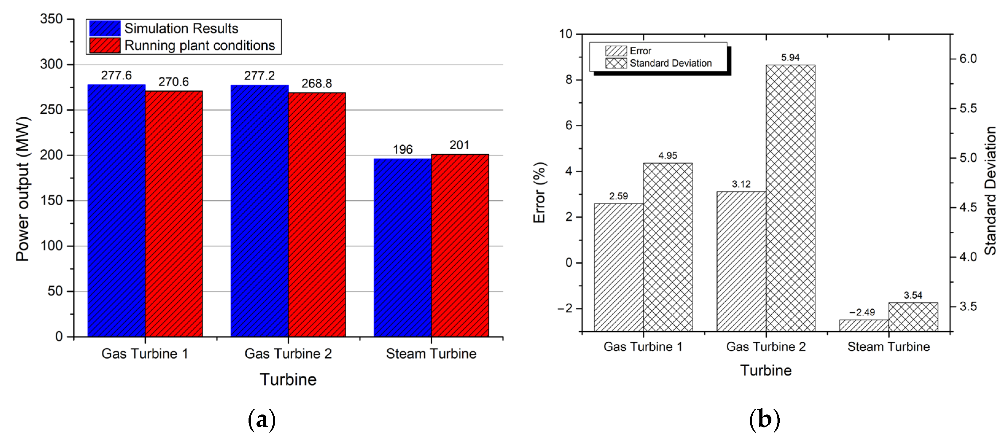
Table 1). The simulation results were validated by the plant’s running conditions based on power outputs from turbines as well as various important process stream conditions. The comparison of power outputs estimated through simulation with plant running conditions is shown in
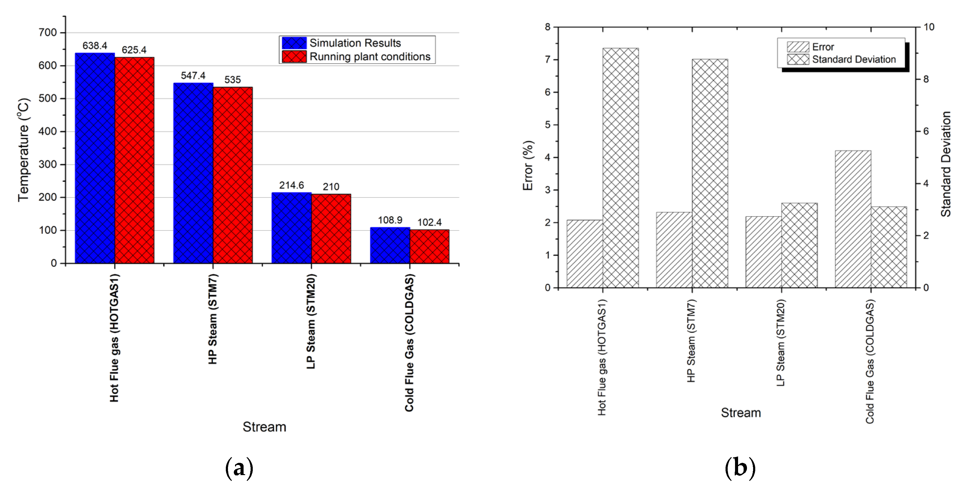
Figure 8. From the figure, it was observed that the simulated model predicted in an acceptable range the power outputs as per plant running conditions. Less than 2% was observed in all the predictions. Similarly, the temperatures of various important operating conditions were compared with simulation results (
Figure 9) and found a close similarity between the simulations and actual plant data. The error lies in the range of 1–5% which shows a good agreement between actual values and simulation estimations. Hence, it can be deduced that the simulated model (NGCC base model) is predicting the results with good confidence.
3.2. Simulation Results for Base Case (NGCC) and Base + PCC + Solar Models
The simulation results regarding the NGCC (base) case and NGCC + PCC with solar (NGCC + PCC + Solar) are tabulated in
Table 5. It was observed that the net NGCC plant capacity was about 750 MW before PCC installation, which was reduced to 6.7% and reached the range of 699 MW. The CO
2 emissions from the existing NGCC plant were estimated at 2,119,318 tons/year by assuming 85% plant efficiency, whereas after the PCC installation, they were reduced to 18,064 tons/year after the installation of PCC using MEA circulation. The removal is estimated to be about 99%, which is the maximum efficiency that could be achieved using any PCC configuration.
3.3. Parametric Investigations
The sensitivity analysis of different important parameters such as natural gas flow and MEA flow rate was conducted to check the stability of the model and its overall performance as per previous research [
13,
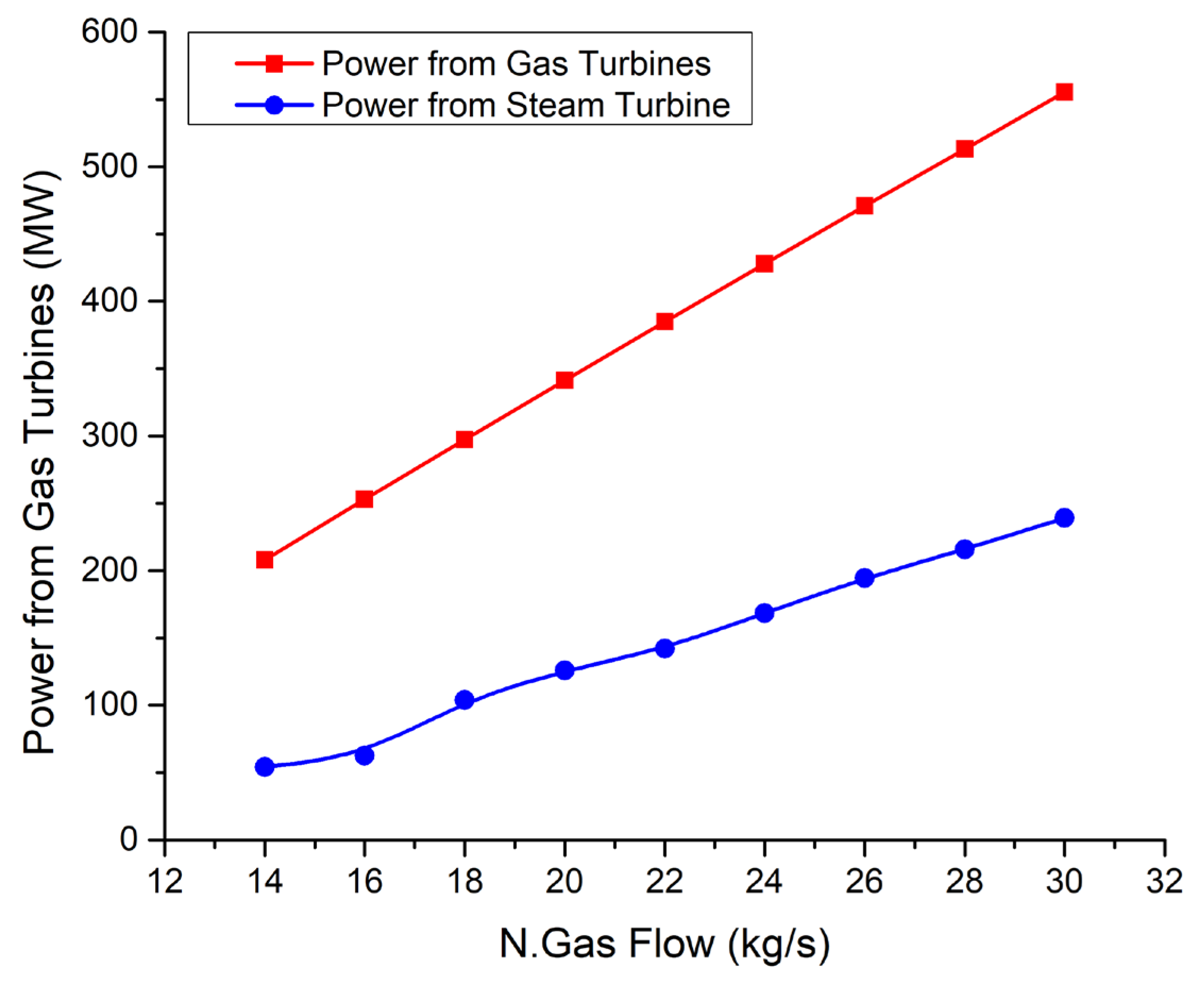
17]. The impact of the natural gas flow rate was observed on total power output from gas turbines, as well as steam turbines along with CO
2 production, as shown in
Figure 10. The natural gas flow rate varied from 14 to 30 kg/s. A linear relationship was observed between the natural gas feed flow rate and power outputs from the turbine. The observed linear relationship between the natural gas feed flow rate and power outputs from the turbine can be attributed to the fundamental principles of thermodynamics and the operation of gas turbines.
As the flow rate of natural gas increases within the specified range (from 14 to 30 kg/s), more fuel is supplied to the combustion chamber of the gas turbine. This leads to a corresponding increase in the rate of combustion and the generation of high-temperature, high-pressure gases. These gases expand rapidly as they pass through the turbine blades, driving the turbine rotor and ultimately producing mechanical work. The linear trend arises because, within this range, the increase in fuel flow rate directly corresponds to a proportional increase in the mass flow rate of the hot gases through the turbine. This consistent increase in the mass flow rate results in a linear increase in the power output of the turbine. It’s important to note that this linear relationship holds within the specified operating conditions and range of natural gas flow rates. Beyond this range, nonlinear effects such as turbine efficiency variations or limitations in combustion dynamics may influence the relationship between fuel flow rate and power output.
At 14 kg/s, the gas turbine produced 209 MW of total power, whereas the maximum power of 556 MW produced from the turbine was received at a flow rate of 30 kg/s flow natural gas. However, steam turbines produced power in the range of 54 to 240 MW. It was noticed that the slope of the increase in power for the gas turbine was a little higher as compared to the power generation from steam turbines. The higher slope of power increase for the gas turbine compared to the steam turbine can be attributed to the inherent differences in their thermodynamic processes. Gas turbines typically exhibit a more rapid response to changes in fuel flow rate due to their faster startup times and simpler operation compared to steam turbines. Additionally, gas turbines operate at higher temperatures and pressures, resulting in a more immediate and pronounced response to variations in fuel input. Conversely, steam turbines, while efficient and reliable, often have slower response times due to the time required to heat water to generate steam and reach optimal operating conditions. Thus, the gas turbine’s ability to quickly adjust to changes in fuel flow rate contributes to its slightly higher slope of power increase compared to steam turbines within the observed range.
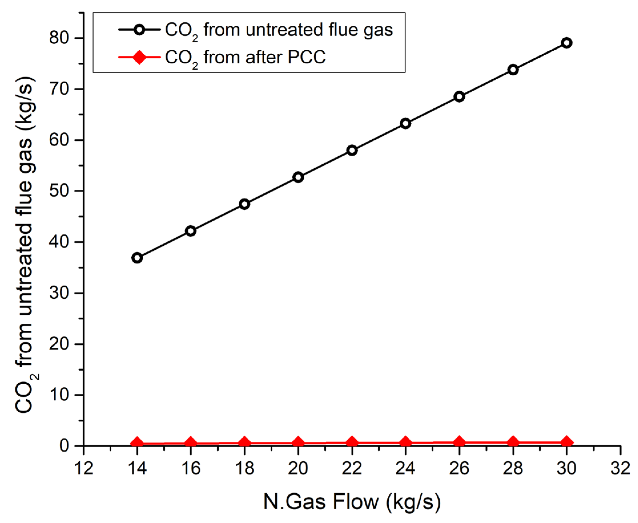
The CO
2 generation is also linearly increased from 36 kg/s to 79 kg/s (1,135,296 to 2,491,344 tonnes/year) with the increasing natural gas flow without PCC (
Figure 11). However, one can observe that after the installation of PCC, CO
2 is much more controlled, and the upper limit is just 0.672 kg/s (21,192 tonnes/year). This is almost 98% removal of CO
2 from the flue gases.
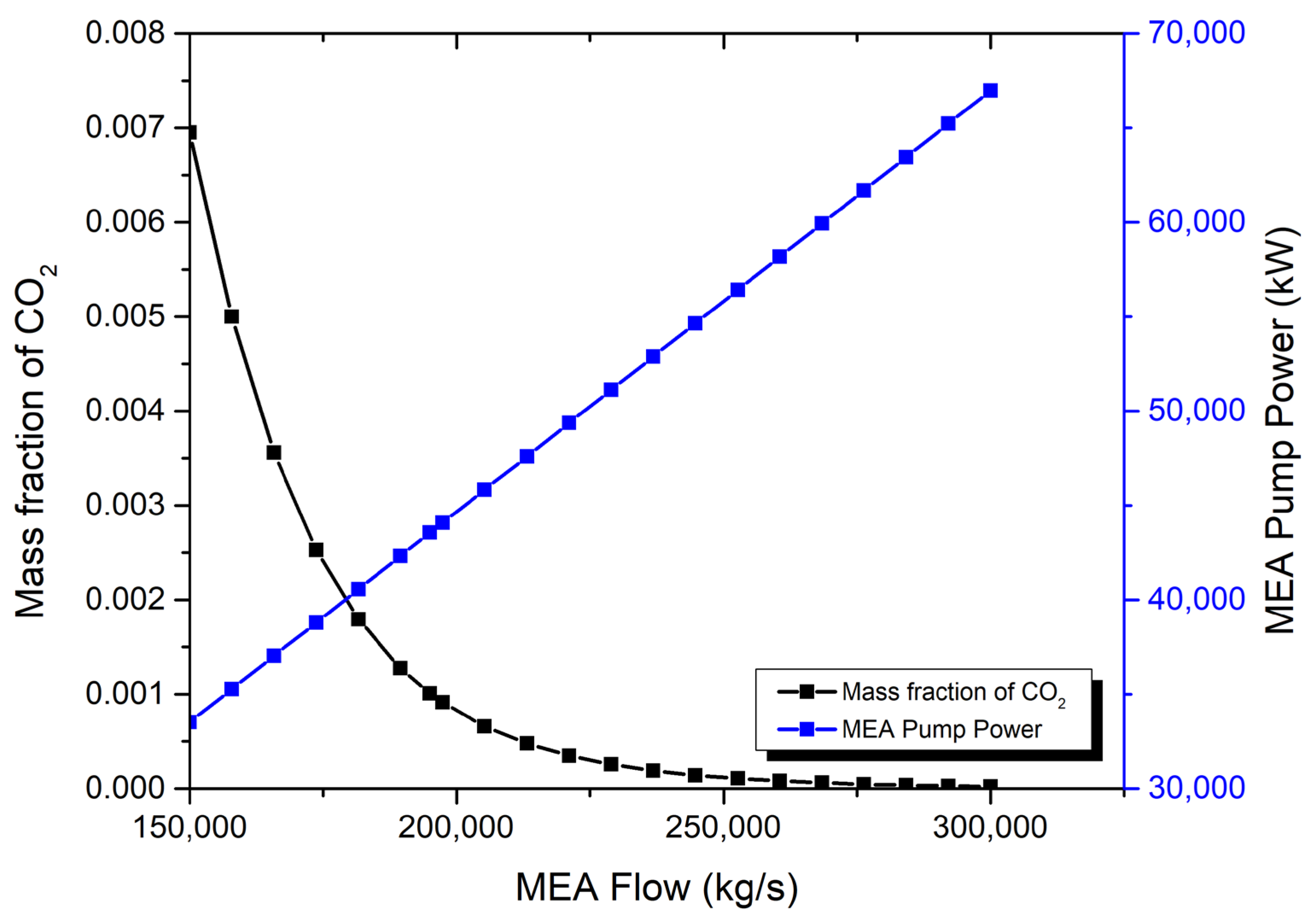
The effect of MEA flowrate in the PCC section on the CO
2 fraction in flue gas and MEA pump duty is shown in
Figure 12. The MEA flowrate was increased from 150,000 kg/s to 300,000 kg/s in the absorption tower. At 150,000 kg/s, the CO
2 mass fraction in stack gas was reduced to less than 1% (0.7%). With the further increase in MEA flow up to 300,000 kg/s, the CO
2 fraction was reached in an almost negligible range. On the other hand, due to the high flow rate, the pumping duty for MEA recirculation has been linearly increased from 33 MW to 67 MW. From this, it has been realized that the 150,000 kg/s MEA flow rate is the most optimized feeding rate in terms of getting less than 1% CO
2 in the stack gas.
The observation that a MEA flow rate for achieving less than 1% CO2 in the stack gas can be explained by considering the absorption kinetics and equilibrium behavior in the absorption tower. At lower flow rates, the MEA solution has sufficient contact time with the flue gas to effectively capture CO2 molecules, resulting in a reduction of the CO2 mass fraction in the stack gas to less than 1%. However, as the flow rate of MEA is increased beyond this optimized point, the additional volume of solvent may not significantly improve CO2 capture efficiency due to limitations in mass transfer and absorption kinetics. Moreover, increasing the MEA flow rate beyond the optimized point requires higher pumping duties for MEA recirculation. This increase in pumping duty indicates that the system is expending more energy to circulate the solvent, without achieving significant improvements in CO2 capture efficiency. Therefore, the observed trend highlights the importance of balancing absorption efficiency with energy consumption in optimizing CO2 capture processes.
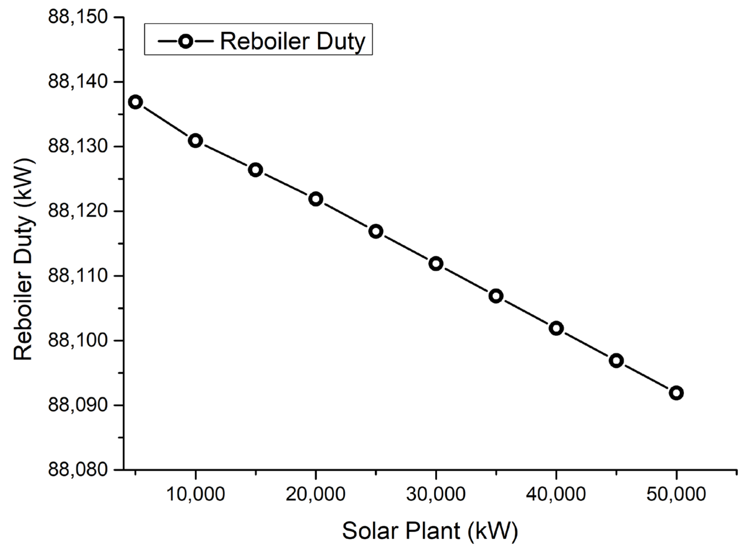
The impact of solar power on the overall duty of the reboiler is investigated, and a linearly decreasing trend is shown in
Figure 13. With 5000 kW of solar power, the additional reboiler duty is estimated at about 88,137 kW to heat the rich MEA in the stripping column. At maximum solar power, i.e., 50,000 kW, the reboiler duty was reduced to 88,092 kW.
3.4. Analysis of Solar Power Plants
The parabolic trough solar collector field was modeled using NREL’s SAM for the NGCC power plant located in Baghdad, Iraq.
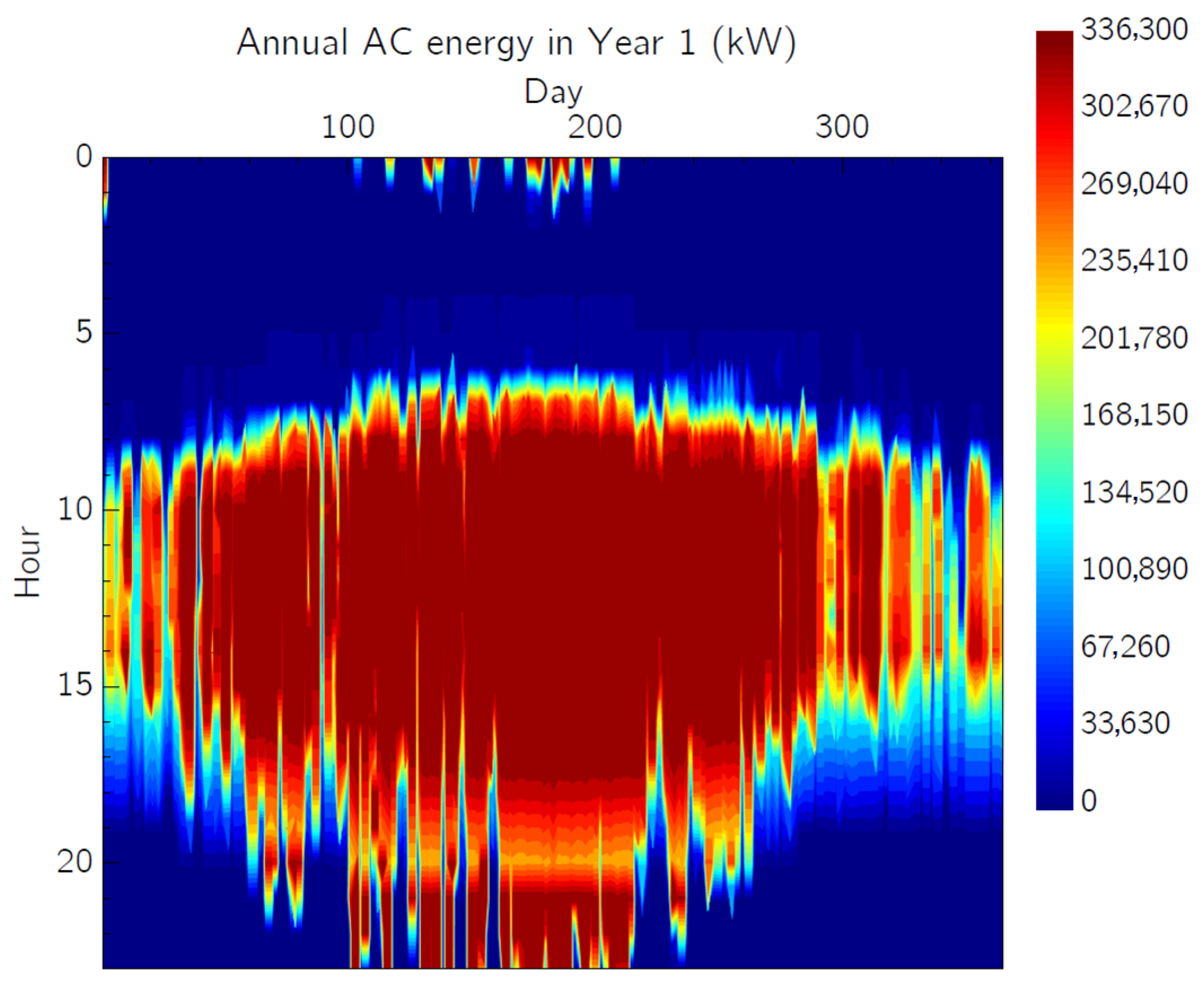
Table 6 describes the overall statistics regarding the annual energy production. According to this, about 984,018,688 kWh
th annual energy potential is lying at the selected coordinates (Baghdad, Iraq), following the strategy of previous research [
33]. The potential of solar energy can also be visualized in
Figure 14, in which annual AC energy in a year is shown. The maximum 336,300 kW of solar energy can be harnessed at the selected coordinates of Baghdad, Iraq.
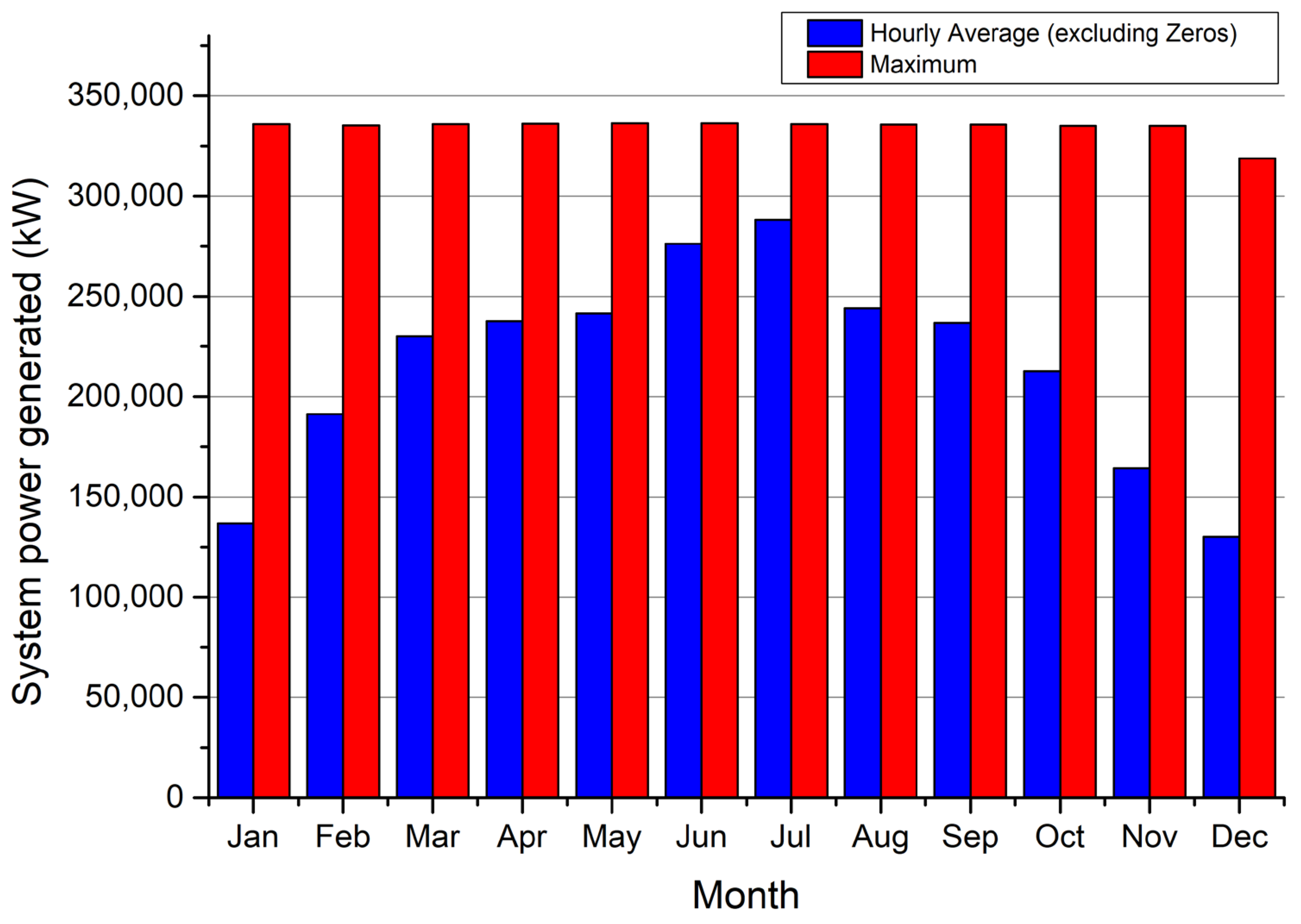
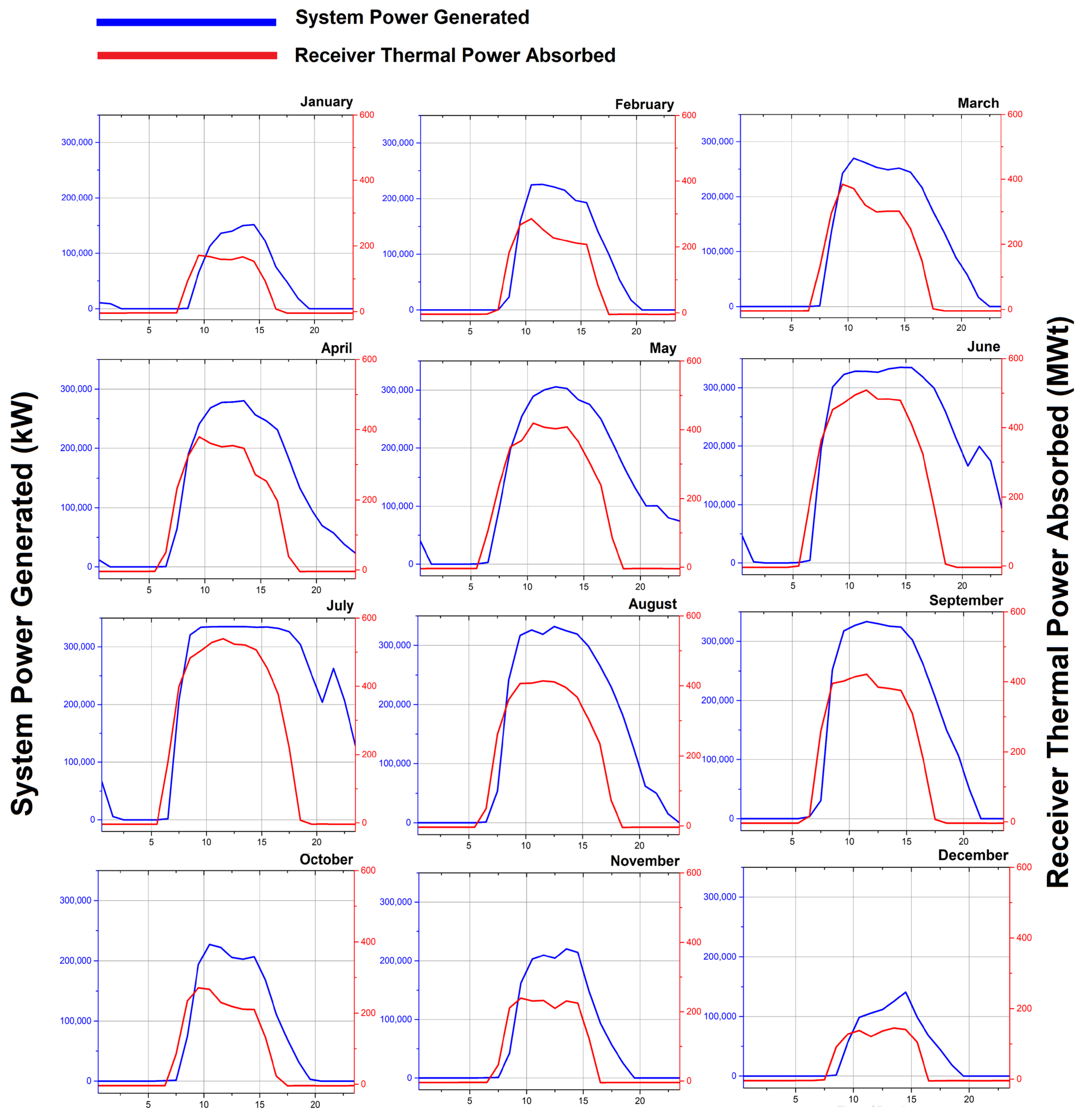
The SAM has also estimated the monthly system power generated, which is shown in
Figure 15. It has been observed that maximum power touches the range of 350,000 kW in most of the months, particularly the months of the summer season (April to September). This can be further verified from
Figure 16, which shows the day-wise system power generation and receiver thermal absorption. The higher curves in the summer months for most of the days are visualized, which proves that enough solar potential can drive the reboiler to capture CO
2 from the flue gases.
Table 7 describes a brief comparison of the results of the current study with those of some other similar studies. From the comparison, it has been observed that mostly MEA solvents are used to efficiently remove CO
2 from the combustion exhaust gases. Solar energy is often used to reduce the PCC energy cost and improve the overall economy of the process. The removal efficiency of current research was observed at 99%, which is almost in the highest range. Hence, the current study showed a significant contribution for the huge capacity of power plants with efficient CO
2 capture.
Overall, the proposed system has numerous advantages, as this proposed solar-assisted system can reduce CO2 from flue gases by utilizing maximum solar energy. Integration of solar thermal energy with PCC technology can significantly reduce CO2 emissions from fossil fuel-based power generation, contributing to climate change mitigation efforts. Solar thermal energy can supplement the heat input required for PCC capture processes, improving overall energy efficiency and reducing fuel consumption. By harnessing solar energy, the proposed system promotes the integration of renewable energy sources into conventional power plants, diversifying the energy mix and enhancing energy security. Moreover, depending on local solar resource availability and energy market dynamics, the use of solar thermal energy may lead to cost savings by offsetting fuel consumption and reducing operational expenses. The adoption of solar-assisted PCC technology aligns with sustainable development goals by promoting the transition to cleaner energy sources and reducing environmental impacts associated with power generation.
Apart from the above advantages, some disadvantages or challenges could also be faced. Among these, the biggest issue is the cost of the system. The upfront capital costs associated with implementing solar thermal collectors and integrating them with PCC systems can be substantial, potentially posing financial challenges for project developers. Moreover, integrating solar thermal energy with PCC processes introduces additional technical complexities, including system design, control optimization, and equipment compatibility, which may require specialized expertise and resources.
3.5. Challenges and Barriers to Implementing and Scaling Up the Solar-Assisted PCC System in Iraq and the Middle East Region
Implementing and scaling up a solar-assisted post-combustion capture (PCC) system in the context of Iraq and the wider Middle East region presents a range of challenges and barriers that must be carefully considered [
36]. One significant challenge is the existing energy infrastructure, which predominantly relies on conventional fossil fuel-based power generation. Integrating a solar-assisted PCC system requires substantial modifications and investments in these established systems, including retrofitting existing plants or constructing new facilities. Additionally, the intermittent use of solar energy resources poses challenges for ensuring reliable and consistent power generation, particularly in regions with variable weather patterns.
Another barrier to implementation is the availability of suitable land for deploying solar collectors at the scale required to meet the energy demands of large power plants [
37]. In densely populated or urbanized areas, finding sufficient space for solar installations may be challenging, necessitating innovative solutions such as rooftops or floating solar arrays. Furthermore, land ownership issues and regulatory complexities may further hinder the acquisition and development of suitable sites for solar power generation.
Moreover, the technical complexity of integrating solar thermal energy with PCC systems introduces operational challenges that must be addressed [
8]. This includes optimizing the coordination between solar collectors [
38], PCC equipment [
39], and other components of the power plant to ensure seamless operation and maximum efficiency. Additionally, ensuring the reliability and durability of solar components in harsh desert environments, common in the Middle East, requires robust engineering solutions and ongoing maintenance protocols.
Regulatory and policy frameworks also play a crucial role in facilitating or impeding the deployment of solar-assisted PCC systems [
40]. Uncertainty surrounding energy policies, including carbon pricing mechanisms and renewable energy targets, can create investment risks and deter stakeholders from committing to long-term projects. Clear and consistent regulatory frameworks that incentivize renewable energy deployment and provide market certainty are essential for overcoming these barriers.
Addressing these challenges will require a multi-faceted approach involving collaboration between governments, industry stakeholders, research institutions, and international organizations. By proactively addressing technical, economic, regulatory, and social barriers, the implementation and scaling up of solar-assisted PCC systems can contribute to the transition towards a more sustainable and resilient energy future in Iraq and the Middle East region.
4. Conclusions
In conclusion, this research illuminates the transformative potential of integrating solar thermal energy and post-combustion carbon capture into the Besmaya Natural Gas Combined Cycle (NGCC) power plant in Baghdad, Iraq. The baseline simulation without carbon capture revealed a robust total power generation capacity of 751 MW, achieving a net plant efficiency of 49.8%. However, with the integration of post-combustion capture (PCC), the total power capacity experienced a modest reduction to 698 MW, accompanied by a slight decline in efficiency to 48%.
Crucially, the environmental impact assessment showcased a remarkable achievement in CO2 emissions reduction. Without solar-assisted PCC, the NGCC plant emitted 2,119,318 tonnes of CO2 annually. Through integration with solar assistance, emissions were slashed by an impressive 99%, reaching a minimal 18,064 tonnes/year. The solar potential analysis for Baghdad indicated an annual solar energy availability of approximately 984,018,688 kWhth. The designed solar power system demonstrated its efficacy by generating 350,000 kW during the summer months, highlighting the feasibility and seasonal adaptability of solar integration. Furthermore, the simulation results delineated the energy distribution within the solar-assisted system, revealing a flue gas cooling duty of 63,926 kWhth and a reboiler duty of 43,217 MWth.
This research not only provides valuable insights into the technical aspects of integrating solar thermal energy into NGCC plants but also underscores its pivotal role in achieving substantial reductions in carbon emissions. As nations worldwide grapple with the imperative of transitioning to cleaner energy systems, the findings presented here contribute to the growing body of knowledge aimed at fostering sustainable and environmentally conscious energy solutions. The outcomes of this study have significant implications for policymakers, energy analysts, and industry stakeholders, guiding future endeavors toward a more sustainable and efficient energy landscape.


