Article

Expansion Characteristics and Creep Test of New Curing Expansion Material for Gas Extraction Boreholes

1
School of Safety and Emergency Management Engineering, Taiyuan University of Technology, Taiyuan 030024, China
2
Faculty of Business and Economics, University of Pécs, 7622 Pécs, Hungary
3
Information Research Institute of the Ministry of Emergency Management, Beijing 100029, China
*
Authors to whom correspondence should be addressed.
Processes 2024, 12(2), 293; https://doi.org/10.3390/pr12020293
Submission received: 23 November 2023 / Revised: 14 January 2024 / Accepted: 23 January 2024 / Published: 29 January 2024

Abstract

:
In order to find the optimal expansion effect of a new curing expansion material so that it can better meet the requirements of the efficient sealing of drilled holes, the expansion and creep characteristics of the new curing expansion material were studied. Based on the creep results of graded loading, the Kelvin–Volgt model was selected to analyze its mechanical parameters, and a new “concentric ring” reinforcement sealing method was proposed. Numerical simulation was employed to analyze and discuss the reinforcement radius and depth of the “protective wall rock hole ring” in the “concentric ring” model, and on-site application experiments were carried out in a soft coal seam. The results show that the “concentric ring” reinforcement sealing method can effectively solve the problems of easy collapse and stress concentration instability in the sealing section of soft coal seams, ensuring long-term and efficient sealing of gas extraction boreholes in soft coal seams. When the diameter of the extraction drilling hole is 100 mm, the optimal reinforcement radius for the “protective wall rock hole ring” is 0.16–0.18 m. A reasonable reinforcement depth of the “protective wall rock hole ring” for drilling in soft coal seams is about 0.8–1 times the width of the roadway. In the on-site application process, experimental boreholes using “concentric ring” reinforcement sealing technology did not show any collapse phenomena, and the volume fraction of extracted gas remained above 30% for the first 30 days. Moreover, the gas volume fraction on the 30th and 60th days was 2.5 times and more than 3 times that of bag sealing boreholes using expanded cement, further proving that the sealing quality of boreholes using “concentric ring” reinforcement sealing is higher.

1. Introduction

Gas extraction plays a crucial role in improving the efficiency of underground mining and solving safety issues in mine production. Numerous facts have proven that gas extraction from coal seams can effectively improve mining efficiency and reduce gas disasters at the source. The effectiveness of gas control indicates that gas pre-extraction can effectively eliminate the problem of gas concentration exceeding the limit in high-gas mine tunnels, and reduce and eliminate the risk of gas outbursts in the mining face from the source [1,2,3]. After years of research and practice, technologies such as hydraulic fracturing, hydraulic cutting, deep hole blasting, and liquid CO2 fracturing have achieved certain results in transforming formation stress, expanding the pressure relief range and increasing coal seam permeability [4,5,6,7,8]. However, there are still many problems with the technology and process of gas extraction in Chinese mines at present. The average gas extraction rate in mines is still less than 30% and the level of gas extraction and utilization is still relatively low [9,10,11,12]. One important reason is that there are many and widely distributed soft coal seam mines in China, and the low strength and poor stability of soft coal seams have led to the problem of difficult sealing of gas extraction boreholes in soft coal seams, which has directly led to the current situation of poor gas extraction efficiency in soft coal seams.
The prerequisite for coal seam gas extraction is to conduct drilling. Due to their own characteristics, soft coal seams are prone to instability, deformation, and even collapse in the borehole opening area under complex environmental disturbances such as gas fields, stress fields, and mining disturbances, as shown in Figure 1. On-site investigation in a soft coal seam mine found that hole collapse often occurs at the hole mouth after drilling and retreating from the soft coal seam, which leads to problems such as the inability to lower the pipe and seal the hole soon enough after drilling is completed, and further dredging and digging the hole will cause great waste from both economic and time perspectives. The large number of gas leakage channels generated by the collapsed hole section also pose great risks to the safety of mines.
In recent years, a large amount of domestic and international research has focused on the stability of extraction drilling and reinforcement and sealing technology. Albooyeh et al. [13] pointed out its impact on drilling stability by studying the rheological properties of drilling fluids. Zhang et al. [14] studied the relationship between borehole collapse pressure and influencing factors. Zheng et al. [15] studied the mechanical parameters of borehole collapse under the action of different types of drilling fluids. Kurlenya et al. [16] proposed a method of blocking coal seam gas drainage holes using barrier shielding. Zhai et al. [17] analyzed the deformation and instability mechanisms of soft coal seams with high gas content and easy outburst during drilling. They believed that the soft structure at the borehole wall was prone to instability and damage, and pointed out that the essential reasons for these phenomena were the stress in the surrounding rock layers of the tunnel and the stress distribution in the borehole. Hashemi et al. [18] studied the effects of different factors on the displacement of pore wall particles. Qi et al. [19] studied the role of stress contour lines in predicting the location, range, depth, and contours of cracks or collapsed wellbore walls. Zhai et al. [20] studied the relationship between coal stress and borehole diameter. Zhang et al. [21] studied the deformation of drilling holes during the process of drilling reinforcement through numerical simulation. They believed that drilling reinforcement would reduce the displacement around the drilling holes and improve the stability of the drilling holes. Zhou et al. [22] established a drilling mathematical model considering gas leakage and used this model to calculate the relationship between extraction concentration and crack width. Papanastasiou et al. [23] discussed a borehole failure model based on fracture mechanics and layer buckling theory, and studied the relationship with experimental data. Wang et al. [24] studied the mechanism of coal seam air leakage and the effects of time, active support pressure, and drainage pressure on air leakage. They proposed an active support sealing method using double expansion materials as sealing materials. Xiang et al. [25] proposed “integrated sealing and isolation” sealing technology, which solved the technical problem of forming gas leakage channels after sealing cracks. On the basis of the traditional “bag-type pressure grouting method” one-time sealing process, Sun et al. [26] proposed an integrated technology concept of sealing and gas leakage disposal.
However, the above studies are all based on stability and reinforcement sealing technology after drilling holes. These technologies and theories make it difficult to solve the problem of easily collapsing holes during drilling, which makes it impossible to seal them. This also leads to unclear and reasonable solutions for hole collapse in the position of drilling holes in soft coal seams, resulting in unsatisfactory sealing effects for gas extraction drilling holes in soft coal seams. We propose a new type of “concentric ring” reinforcement sealing method based on the stability research results of an existing extraction drilling sealing section combined with existing reinforcement sealing technology research. Meanwhile, key parameters such as reinforcement range and depth are studied through numerical simulations. On this basis, on-site industrial application experiments are carried out in a soft coal seam. These studies have significant theoretical value and practical significance for efficient gas extraction and utilization in soft coal seam mines.

2. Methodology

After drilling in soft coal seams, the sealing section of the hole collapses, causing the sealing to fail and the stress concentration to become unstable, resulting in the rapid failure of the sealing drilling extraction effect. This not only blocks the passage of gas emissions and flow, seriously affecting the efficiency of gas extraction, but also increases the difficulty of sealing engineering [27,28]. From this, it can be seen that a reinforcement sealing technology that can stabilize the position of the borehole sealing section to prevent hole collapse and effectively support the stress concentration area of the sealing section to resist deformation is of great significance for improving the effectiveness of gas extraction in soft coal seam mines.

2.1. Physical Model of “Concentric Ring” Strengthening Sealing

The sealing of gas extraction boreholes in soft coal seams in China mainly adopts organic material sealing and “two plugs and one injection” sealing. According to previous research results, the existing sealing methods for gas extraction boreholes in soft coal seams cannot achieve efficient sealing of boreholes; it is neither possible to ensure the complete stability of the soft coal seam orifice section nor possible prevent instability and deformation of the stress concentration area in the sealing section.
Solutions to the instability of underground drilling in coal mines mainly include two aspects. On the one hand, from the perspective of drilling, they include improving drilling tools, such as using high-power drilling rigs that are triangular, spiral, etc., or improving pressure air chip removal and dry–wet mixed drilling to improve slag removal efficiency and ultimately ensure the hole formation rate. On the other hand, casing is used to protect the hole, but this method has high material and transportation costs, and it is difficult to recover the casing in soft coal seams. The above methods cannot fundamentally prevent the collapse of the sealing section of soft coal seam drilling holes and the instability and deformation of the stress concentration area. Considering the shortcomings of current sealing technologies in China and the experience of foreign sealing technologies, based on technical ideas such as roadway spray support and drilling reinforcement technology, we propose a new type of “concentric ring” reinforcement sealing method, as shown in Figure 2. This shows, with the center point of the coal seam drilling hole as the center, a “grouting sealing ring” and a “protective wall rock hole ring” outwards in sequence. The “grouting sealing ring” is made through a “two plugs and one injection” grouting process, located in the stress concentration area of the drilling sealing section. The “protective wall rock hole ring” is achieved by pre-grouting the protective wall holes, located in the damaged area of the sealing section of the drilling hole.
The basic technical principle is as follows: (1) The main idea is to transform the fragmented and unstable “coal hole” in the borehole area of soft coal seams into a denser and more stable “rock hole” and to use conventional drilling machines to drill 5–10 m. (2) Using large-diameter drilling to expand the reinforcement section, it was found through on-site testing that the diameter of the expansion hole should generally be increased by 10–20 cm on the basis of the pre-drilled diameter. (3) The grouting system is used to reinforce the fractured area (pre-reinforced section) of the initial drilling area. After the reinforced section is completely solidified, conventional extraction drilling is carried out, ultimately forming a “protective wall rock hole“. The “protective wall rock hole” can effectively enhance the stability of the initial drilling area and prevent borehole collapse.
On the basis of completing the “protective wall rock hole” mentioned above, a grouting system is used to reinforce and seal the stress concentration area with “two plugs and one injection” grouting. Through double pressure grouting before and after, not only can the early sealing of air leakage cracks at the hole opening be achieved, but also the cracks generated in the stress concentration area can be effectively sealed.
Overall, the “concentric ring” reinforcement sealing process not only shortens the sealing length and saves materials such as bag seals, but also technically ensures reasonable and orderly drilling and sealing processes.

2.2. Mechanical Model of “Concentric Ring” Strengthening Sealing

As shown in Figure 3, after drilling in the coal seam of the mine, the direction along the drilling hole diameter is sequentially divided into a crushing zone, plastic zone, elastic zone, and original rock stress zone. The reinforcement area of the “protective wall rock hole” can effectively prevent deformation of the coal body around the hole and avoid blockage, collapse, and shrinkage of the borehole. In order to facilitate the analysis of the “concentric ring” reinforcement sealing model, the following basic assumptions are made:
(1)
The coal body around the drilling hole is homogeneous and continuous, and is an isotropic ideal elastic–plastic body with a plasticity condition of Mohr–Coulomb guidelines.
(2)
The self-weight of the coal body around the borehole is not considered, and the horizontal stress of the original rock is uniformly distributed.
(3)
Drilling is considered to be horizontally arranged and sufficiently long, with a circular cross-section and a lateral pressure coefficient of 1 around the borehole. The stress in the coal and rock mass is isotropic and isobaric.
(4)
Regardless of the damage caused by the drilling of the “protective wall rock hole ring” section, drilling and grouting reinforcement are carried out simultaneously.
As shown in Figure 3, the boundary conditions of the plastic zone of the coal body around the reinforced borehole for the sealing section “protective wall rock hole ring” are
σ r p = P j
The radius of the plastic zone at the mouth of the reinforced drilling sealing section can be obtained by
R p = r 0 ( σ 0 + C cot φ ) ( 1 sin φ ) P j + C cot φ 1 sin φ 2 sin φ
where σ r p is radial stress in the crushing zone around the borehole, MPa; Pj is the pre-reinforcement stress, MPa; Rp is the radius of the plastic zone, m; r0 is the drilling radius, m; σ 0 is the original stress, MPa; C is the cohesive stress, Mpa; and φ is internal friction angle, °.
Displacement of the elastic–plastic zone at the orifice of the reinforced drilling sealing section
u 0 = sin φ 2 G r 0 ( σ 0 + C cot φ ) ( σ 0 + C cot φ ) ( 1 sin φ ) P j + C cot φ 2 sin φ 1 sin φ
where u 0 is the displacement of the elastic–plastic zone at the orifice and G is the coal shear modulus, MPa.
Stress in the damaged area of the borehole sealing section after reinforcement is
σ r s = ( P j ) ( r r 0 ) 2 sin φ 1 sin φ σ θ s = ( P j ) ( r r 0 ) 2 sin φ 1 sin φ × 1 + sin φ 1 sin φ
where σ r s is radial stress in the failure zone of the orifice, MPa; σ θ s is tangential stress in the failure zone of the orifice, MPa; and r is the distance from the center point of the borehole, m.
Similarly, for the stress concentration location of the sealing section, as shown in Figure 4, after completing bag-type “two plugs and one injection” sealing grouting, the grouting sealing support stress acts on the crushing area; the boundary conditions of the “grouting sealing ring” of the sealing section are
σ r p = P i
The radius of the plastic zone in the grouting sealing area is
R p = r 0 ( σ 0 + C cot φ ) ( 1 sin φ ) P i + C cot φ 1 sin φ 2 sin φ
where Pi is the grouting sealing support stress, MPa.
Displacement of the elastoplastic zone in the grouting sealing area
u 0 = sin φ 2 G r 0 ( σ 0 + C cot φ ) ( σ 0 + C cot φ ) ( 1 sin φ ) P i + C cot φ 2 sin φ 1 sin φ
Stress in the failure zone of the grouting sealing area is
σ r s = ( P i ) ( r r 0 ) 2 sin φ 1 sin φ σ θ s = ( P i ) ( r r 0 ) 2 sin φ 1 sin φ × 1 + sin φ 1 sin φ
Equations of equilibrium:
σ x x + τ y x y + f x = 0 σ x y + τ x y x + f y = 0
Plane strain equation:
ε x = u x ε y = v y γ x y = v x + u y
Strain equation around the borehole:
ε x = 1 μ 2 E σ x μ 1 μ σ y ε y = 1 μ 2 E σ y μ 1 μ σ x γ x y = 2 1 + μ E τ x y
Compatible equations:
4 ϕ x 4 + 2 4 ϕ x 2 y 2 + 4 ϕ y 4 = 0
where σx is the plane stress component of the x-axis, MPa; σy is the plane stress component of the y-axis, MPa; τxy is the shear stress, MPa; εx is the plane strain component of the x-axis; εy is the plane strain component of the y-axis; γxy is the shear strain; u is the displacement along the x-axis, m; v is the displacement along the y-axis, m; μ is the Poisson’s ratio of the surrounding rock of the tunnel; and ϕ is the stress function.
With the above analysis, it can be found that for a coal body in the “protective wall rock hole ring” area of the sealing section, due to the pre-reinforcement and sealing of the surrounding area of the drilling hole before drilling, the hole opening reinforcement stress Pj of the drilling hole and changes in its physical characteristics are given in advance at the hole opening position. From Equations (2) and (3), it can be observed that, due to the reduction in displacement u0 in the elastic–plastic zone around the drilled hole after reinforcement, the relative displacement of the drilling surrounding rock is also reduced to a certain extent. In particular, the stress concentration in the pressure relief zone around the sealing section orifice is improved, and gas extraction drilling is more stable in the reinforcement area, which can effectively ensure the stability of the sealing section orifice position after drilling.
At the same time, it can be observed that for the stress concentration area of the sealing section, due to the existence of the support stress Pi of the high-strength sealing material in the bag-type “two plugs and one injection”, as shown in Equation (4), radius Rp of the plastic zone is reduced, which allows the drilling surrounding rock to be in a relatively stable elastic deformation state within a larger range. Therefore, the stress concentration area of the drilling sealing section after reinforcement can be obtained. High-strength sealing materials can effectively resist the deformation and instability of drilling holes under a load.

3. Results and Discussion

3.1. Numerical Simulation Study of the “Concentric Ring” Strengthening Sealing Model

Numerical simulation is an indispensable tool in research and exploration. The previous section analyzed the “concentric ring” reinforcement sealing model of the drilling sealing section. However, in actual gas extraction and sealing engineering, key technical parameters such as the radius and depth of the “protective wall rock hole ring” at the sealing section hole position directly affect the effectiveness of drilling reinforcement sealing. Therefore, this section focuses on research and analysis of the main parameter indicators of the reinforced sealing model. Due to limitations of the size of the testing machine and indoor testing, it is not easy to conduct in-depth quantitative analysis and research. Therefore, the numerical simulation method is used to study the relationship between the radius of the “retaining wall rock hole ring” and the deformation under load under ideal conditions. At the same time, a reasonable reinforcement radius of the “protective wall rock hole ring” is obtained by studying the law between the size of the broken zone in the sealing section and the stress concentration radius.

3.1.1. Study of the Radius of the “Protective Wall Rock Hole Ring”

(1)
Model Building
Taking the gas extraction boreholes in this coal seam as the modeling object, the extraction boreholes are arranged on one side of the tunnel and the pre-reinforcement radius of the “protective wall rock hole ring” for reinforcement and sealing are studied. A geometric model diagram is shown in Figure 5. COMSOL Multiphysics 5.6 numerical simulation software is employed to deduce the deformation of surrounding rock under stress during drilling, establish a three-dimensional coal seam model, and analyze the stress and displacement around the hole. The selected model is 70 m × 3 m × 18 m; the cross-section of the roadway is horseshoe-shaped, with a spacing of 6 m between the arches on both sides. The drilling hole diameter for extraction is 0.1 m, with a depth of 50 m. The range of the pre-reinforced sealing radius is 0.12 m–0.2 m, and the pre-reinforced sealing length is 5 m.
The numerical simulation adopts free tetrahedral mesh partitioning, as shown in Figure 6 and Table 1. The entire geometric area is customized with mesh vertices of 133,574, tetrahedral elements of 725,626, edge elements of 4208, and vertex elements of 24. The minimum unit mass is 0.2503, the average unit mass is 0.6964, and the mesh volume is 3670 m3.
The radius of the tunnel in the geometric model is much larger than the diameter of the extraction drilling hole. The coal body is subjected to the stress of the original rock, and the tunnel excavation will cause stress concentration around the tunnel, resulting in displacement around the drilling hole in the grouting reinforcement section. Due to the fact that the length of the tunnel is much greater than the radial size of the tunnel, all stress and deformation components on the tunnel cross-section are functions of plane coordinates, which are approximately assumed not to change with the length of the tunnel. Considering the surrounding support of the tunnel, based on ideal elastic–plastic theory, a model is established for the loading of the reinforcement section after tunnel excavation. The calculation model is shown in Figure 7, and combined with on-site practice and experimental testing, the boundary conditions and initial parameters are shown in Table 2.
In the substitution of boundary conditions, displacement boundary conditions are ( u ) s = 0 and ( v ) s = 0 . The stress boundary condition is the top load equation: FA = ρh. And the overburden stress is set at 20 MPa.
(2)
Discussion
According to the calculated distribution of displacement D around the borehole, as shown in Figure 8 and Figure 9, it was found that due to stress concentration, displacement occurred at the borehole opening, with a displacement range of 62–68 mm. Due to the first pre-reinforcement of the borehole in the reinforced section after reinforcement and sealing, the bearing capacity of the borehole’s main stress direction increased, and displacement D around the borehole decreased with the increase in reinforcement radius. Moreover, due to the effect of principal stress, the upper displacement around the hole is more severe.
Due to the reinforcement of the “protective wall rock hole” section of the borehole, the reinforcement section around the borehole bears the maximum principal stress direction and resists the deformation effect of the maximum principal stress on the borehole. The displacement u at the top of the borehole shows a decreasing trend from the borehole opening to the interior of the borehole, as shown in Figure 10. It can be observed that displacement u generated by the borehole at the borehole opening is the largest, and when the reinforcement radius r is at least 0.12 m, the displacement at the top of the borehole is 12.8 mm. This also reflects, on the one hand, that the position of the borehole opening is prone to deformation and collapse. Due to the setting of the drilling reinforcement depth at 5m in the simulation test model, displacement u of the drilling hole at 5 m inside the hole is the smallest, only about 5 mm. The drilling stability is good, which has an important impact on solving the deformation and instability of the drilling hole in the sealing section.
As shown in Figure 11, different reinforcement radii r also have a significant impact on the variation in displacement u at the top of the borehole. It can be seen that as the reinforcement radius r increases from 0.12 m to 0.2 m, displacement u at the top of the borehole at different positions within the borehole shows a decreasing trend. Therefore, a larger reinforcement radius can make the borehole more stable, which is of great significance for solving the problem of poor gas extraction caused by the instability of the sealing section. In order to further determine the effect of the reinforcement radius, the variation pattern of different reinforcement radii r and displacement u at the top of the borehole is plotted in Figure 12. It can be seen that as the reinforcement radius increases, displacement u at the top of the borehole gradually decreases from fast to slow. When the reinforcement radius r decreases from 0.2 m to 0.12 m, displacement u at the top of the borehole increases from 0.538 mm to 0.236 mm. From the variation pattern, it is found that when the reinforcement radius r is greater than 0.16 m, the displacement at the top of the borehole decreases slowly. Based on the actual situation on-site and a comparison of the displacement changes, it can be concluded that the optimal reinforcement radius r for the “protective wall rock hole ring” should be between 0.16 m and 0.18 m when the extraction borehole diameter is 100 mm.

3.1.2. Study of the Depth of the “Protective Wall Rock Hole Ring”

(1)
Model Building
In order to explore a reasonable value for the pre-reinforcement depth for the “protective wall rock hole ring”, a simulation experiment was conducted using FLAC3D 7.00 numerical simulation software. The experimental physical model arranges coal seam drilling holes parallel to one side of the tunnel, and the length of the tunnel is much larger than the diameter of the extraction drilling hole. The coal body is subjected to the stress of the original rock, and the tunnel is excavated in the coal seam. The extraction and drilling holes are arranged horizontally on one side of the tunnel. The physical model is shown in Figure 13, and the stress situation of the model tunnel and drilling holes is analyzed using the FLAC3D 7.00 numerical simulation method.
Establishing a model in FLAC3D software, and based on the on-site soft coal seam situation, the model adopts parameters as shown in Table 3. Combined with the actual engineering situation, the model load is 15 MPa, the borehole diameter is 100 mm, the length is 7500 mm, and the tunnel diameter H is 5–9 m (divided into five groups as shown in Table 4). The circular tunnel is located in the center of the model, and the extraction borehole is located on the right side of the circular tunnel. The borehole is arranged perpendicular to the tunnel. The vertical displacement of the bottom surface of the model is fixed, and the horizontal displacement on both sides is fixed, as shown in Figure 14. The model uses the Mohr–Coulomb yield criterion to determine failure:
f = σ 1 σ 3 1 + sin φ 1 sin φ 2 C 1 + sin φ 1 sin φ
where σ1 and σ3 are the maximum and minimum principal stresses, MPa. When f > 0, the material undergoes shear failure; when σ3σT, the material undergoes tensile failure.
(2)
Discussion
Using the null model to set up the tunnel, the displacement of the left, right, bottom, front, and rear surfaces of the fixed model is 0, and the overburden stress is 15 MPa. The stress distribution around the tunnel can be calculated, as shown in Figure 14. According to relevant research on the division of stress in tunnel drilling, the redistribution of stress generated after tunnel excavation does not change much for σx and σy, but changes significantly for σz. Therefore, the distribution of σz is mainly calculated.
Figure 15 shows the distribution changes of vertical stress σz at different depths of the borehole. It can be seen from the figure that the vertical stress σz of the borehole rapidly increases to its maximum at around twice the diameter of the tunnel, which is the stress concentration area of the borehole. Due to the fact that the stress concentration area is located at the critical elastic–plastic position of the coal body around the drilling hole, it is determined that the stress concentration area inside the on-site drilling hole generally appears in an area about twice the width of the tunnel. For gas extraction drilling in soft coal seams, the coal body in the pressure relief zone where the stress decreases is severely broken, and the coal wall often deforms and collapses inside the drilling hole. At the same time, a large number of gas leakage channels are also generated, seriously affecting the gas extraction effect. Therefore, in order to effectively prevent the collapse and instability of the sealing section in the soft coal seam, the depth of the “protective wall rock hole ring” should exceed the range of the damaged area inside the borehole.
Due to the numerous factors that affect the size of the fractured zone in the borehole, such as the depth of coal seam burial, coal properties, mining disturbance, and support methods, the formation and development of fracture plasticity are all affected. This article focuses on the influence of tunnel radius. On this basis, this article summarizes the relevant literature on the relationship between the size of the pressure relief failure zone and the stress concentration plastic zone in soft coal seam boreholes using methods such as theoretical calculation, drilling debris quantity, and drilling observation, as shown in Table 5. Based on the analysis of existing research and the numerical simulation results of FLAC3D for the location of stress concentration in boreholes, it is proposed that a reasonable pre-reinforcement depth of the “protective wall rock hole ring” for soft coal seam boreholes should be around 0.8 to 1 times the tunnel width.

3.2. Field Application of the “Concentric Ring” Strengthening Sealing Method

An on-site test was conducted in the N2106 transportation roadway of a mining area in Shanxi Province, China. The coal body of the working face has a firmness coefficient fc < 0.5, which makes it a soft coal seam. The N2106 transportation roadway has no special geological structure, and the on-site measured coal seam gas content is 7.82 m3/t, with a total gas emission of 2.16 m
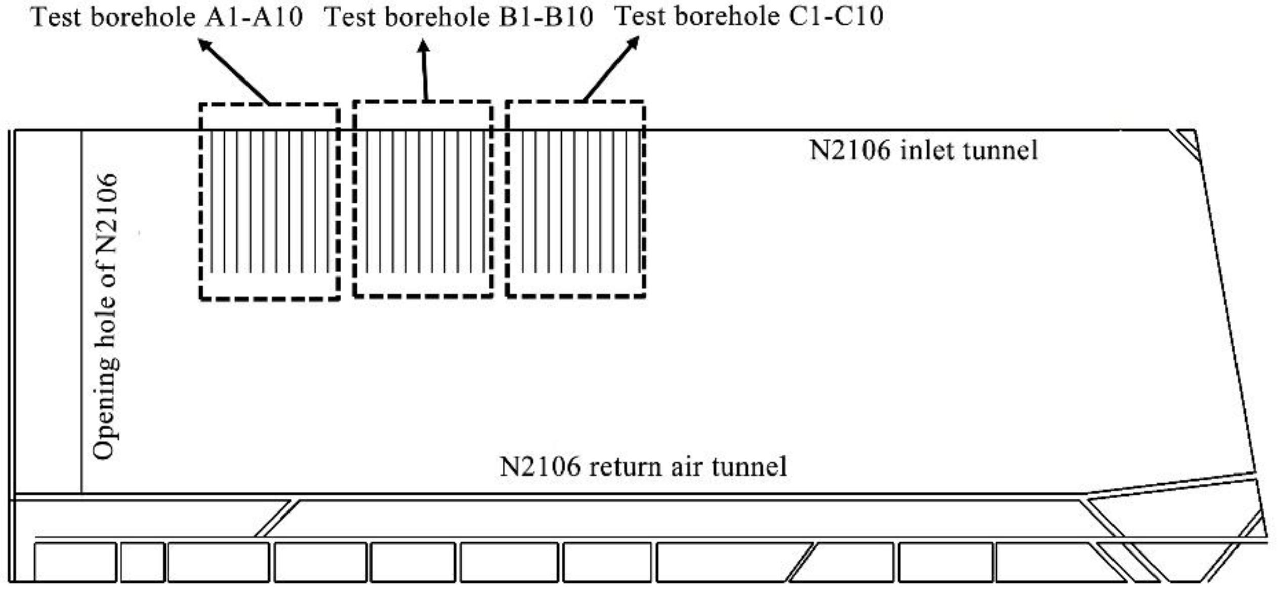
3/min. On-site drilling is gas extraction drilling along the coal seam, which is drilled from the N2106 transport roadway towards the coal body of the working face. The hole is opened from the upper side of the tunnel, perpendicular to the tunnel, and continuously extends into the coal body. Each drilling hole should be sealed and integrated into the gas extraction network in a timely manner after construction. The coal body in the experimental area has not been disturbed by mining, and its strength is relatively weak, belonging to a soft coal seam. The layout of the experimental boreholes is shown in Figure 16.
This on-site test was divided into three groups, each consisting of ten boreholes. The first group used ordinary cloth-bag-type “two plugs and one injection” sealing technology, and the sealing material used was an ordinary expanded cement sealing material. The second group adopted a new reinforcement sealing technology, and its sealing material was an ordinary expansion cement sealing material. On the basis of adopting new reinforcement sealing technology, the third group used new sealing materials for grout sealing. The three sets of test boreholes were recorded as A1–A10, B1–B10, and C1–C10, respectively.
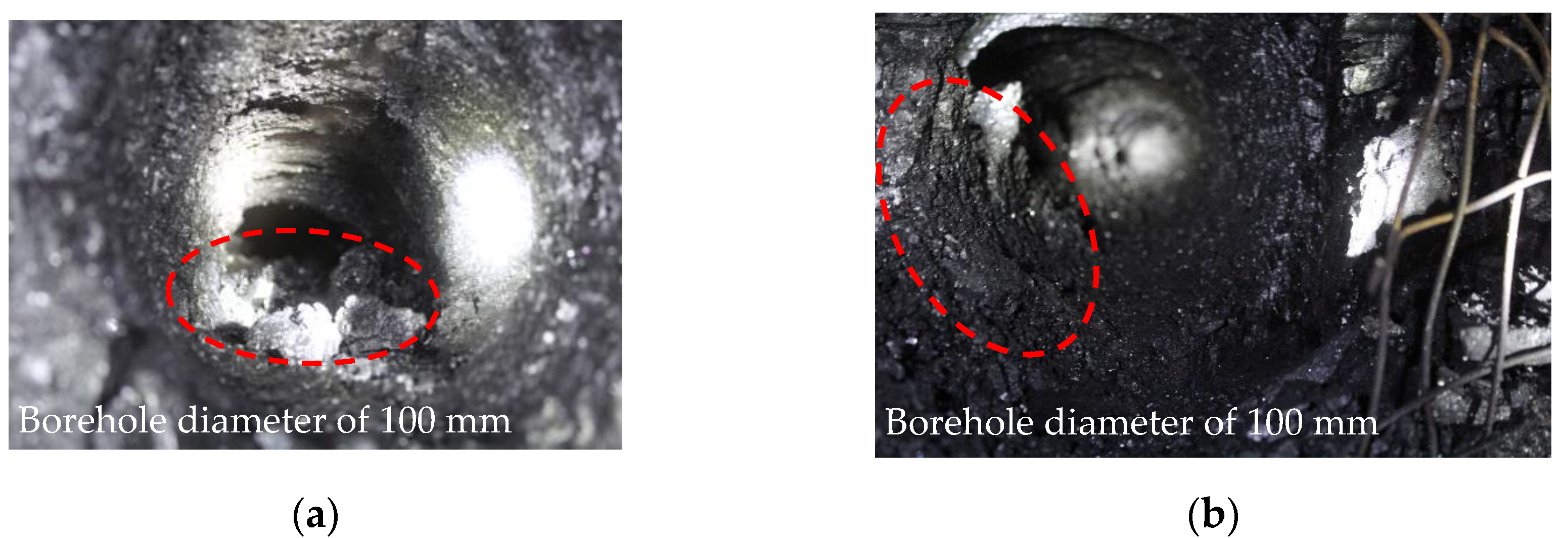
In this on-site test, a total of 13 boreholes were sealed using the ordinary bag-type “two plugs and one injection” sealing technology, and 10 boreholes were effectively drilled. Among those, 7 boreholes experienced collapse at the hole mouth after drilling back and were later cleared through secondary drilling. Using new reinforcement and sealing technology to seal 16 boreholes, we effectively drilled 10 boreholes without any occurrence of hole collapse at the borehole opening position. There were 12 boreholes sealed with new reinforcement sealing technology and materials, and 10 effective boreholes were drilled without any collapse at the borehole opening.
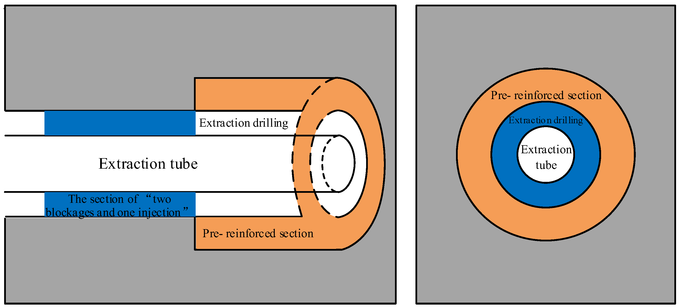
In order to investigate the on-site application effect of new reinforcement sealing technology and new sealing materials, more than 30 coal seam extraction boreholes were constructed in the N2106 working face with an inclination angle of −1–2° and an angle of 90 ° with the centerline of the tunnel. The designed depth of the boreholes was 130 m, and the average depth of the completed boreholes was 127 m. According to the research results of the new sealing technology, drill bits with a diameter of 140 mm were selected for drilling the new reinforced sealing holes in Groups B and C, with a pre-reinforcement depth of 6 m, and the hole opening was sealed with expansion capsules for reinforcement grouting. The sealing depth of drilling holes in Group A was 16 m, and the sealing depth area of bag sealing in Groups B and C was 6–16 m. Under the same conditions, three sets of test boreholes were monitored on-site for a period of three months.
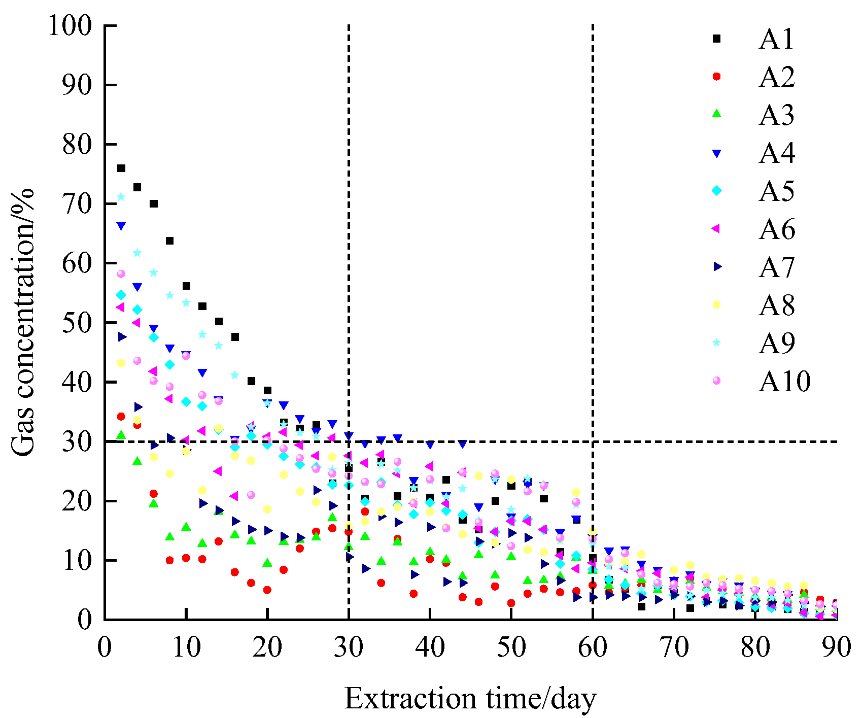
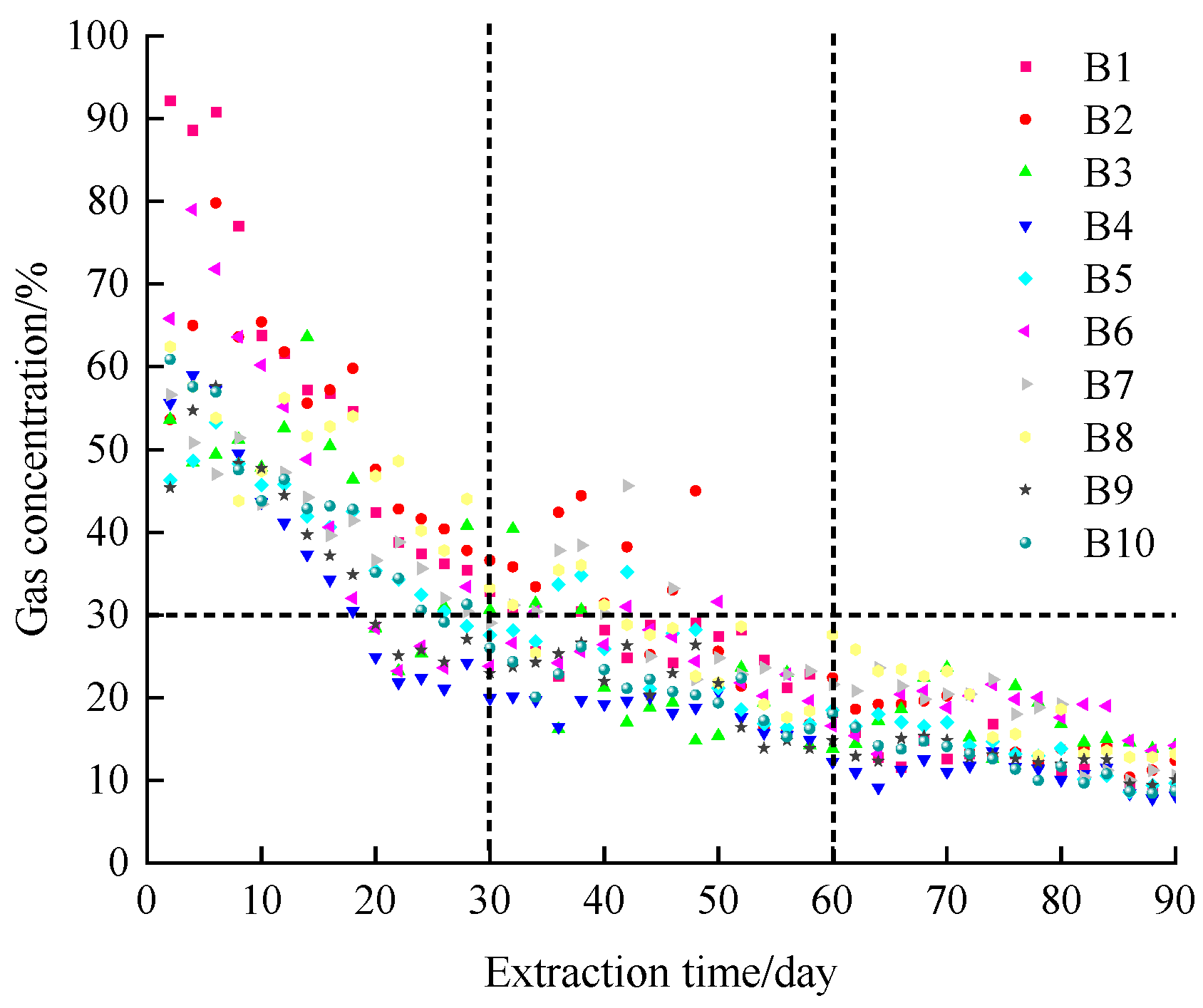
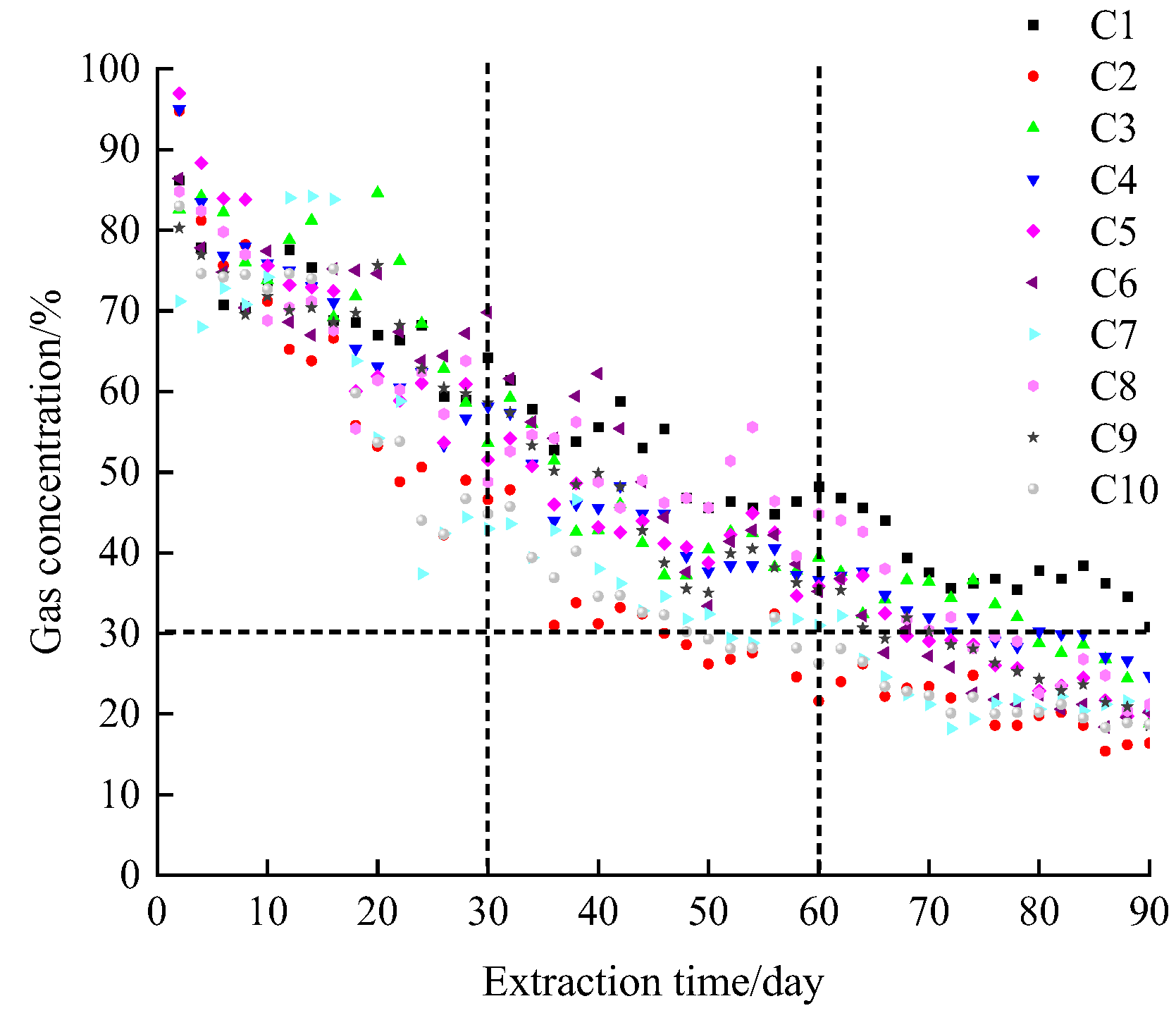
According to the three-month gas concentration detection results of three sets of testing boreholes at the underground site, as shown in Figure 17, Figure 18 and Figure 19, the interval between testing boreholes was one day, and the final average value was taken for each shift on the same day of testing.
By comparing and analyzing Figure 17, Figure 18 and 
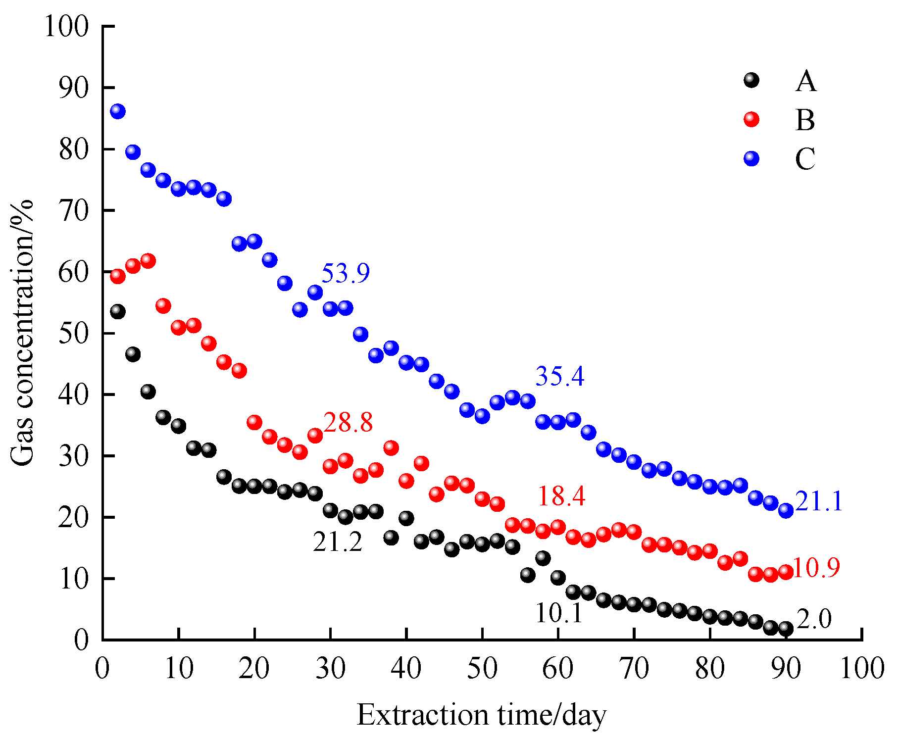
Figure 19, it can be found that after 30 days of extraction, the concentration of test boreholes in Group A decreased to within 30%. The average concentration of boreholes in Group A at 30 days of extraction was 21.2%, and the gas concentration in boreholes decreased significantly from 30 to 60 days of extraction. The average concentration of extraction at 60 and 90 days of extraction was only 10.1% and 2.0%, respectively. The gas concentration in the test boreholes of Group B was basically above 30% within 30 days before extraction, but after 30 days of extraction, most boreholes began to decline and decrease to within 30%. The average gas concentration on the 60th day of extraction was 18.4%. After 60 days of extraction, the gas concentration in Group B boreholes was relatively low, with an average concentration of only 10.9% at 90 days. The test boreholes in Group C ensured a gas extraction concentration of over 30% at 60 days before extraction, with high stability and sustainability of gas concentration. The gas concentration at 30 days of extraction was 53.9%, and the average gas concentration at 60 days of extraction was still greater than 30%.
In order to improve and compare the sealing effect of three test boreholes, four representative boreholes were selected from each group after 30 days of extraction. The negative pressure at the orifice and the pure gas flow rate that characterized the sealing quality were selected for comparative analysis. The comparison results are shown in Figure 20. It was found that under the same extraction time conditions, the gas concentration extracted from Group C was significantly higher than the other two groups, fully demonstrating that the use of new reinforcement sealing technology and new sealing materials greatly improved the gas extraction effect.
According to comprehensive comparison of the sealing effect parameters of the three test boreholes according to Table 6, it can be found that the negative pressure at the orifice of the Group C boreholes was significantly higher than that of the other two test boreholes. Based on the concentration and mixed flow rate, the final gas pure flow rate was calculated, and the gas pure flow rate of Group C was also significantly higher than that of the other two groups. In addition, the suction negative pressure of the N2106 working face was 15 kPa, and the negative pressure at the orifice of the Group C test boreholes still maintained a high level after 30 days of extraction. This indicates that the sealing quality of the Group C test boreholes was stable for a long time and there would be no collapse or leakage.
Based on the above analysis, it can be concluded that the testing drilling hole of Group C using new reinforcement sealing technology and materials ensured a good gas extraction effect for a long time. Compared to Group A, which used a conventional bag-type with two plugs and one injection to test the sealing effect of the drilling hole, Group B used a new reinforcement sealing technology to avoid collapse before sealing the drilling hole, and the drilling hole also had a better sealing effect compared to the testing drilling hole of Group A due to the double grouting and pre-reinforcement of the broken coal body. However, due to the inherent defects of the sealing material, it could not resist the instability of the drilling sealing section, so the test drilling hole of Group B could not guarantee a high extraction level for a long time.

4. Conclusions

(1)
The physical and mechanical model of “concentric ring” reinforcement sealing can improve the stress concentration in the pressure relief area around a sealing section hole, and gas extraction drilling after drilling is more stable in the reinforcement area. This can effectively ensure the stability of the sealing section hole position after drilling, and high-strength sealing materials can effectively resist the deformation and instability of drilling after being loaded. This technology can be further promoted and applied to drilling, sealing, and material development in other fields.
(2)
The relationship between the radius of the borehole tunnel and the radius of the peak point of borehole stress was mastered through numerical simulation experiments. It was found that a reasonable reinforcement depth of the “protective wall rock hole ring” in soft coal seam boreholes should be about 0.8–1 times the width of the tunnel. When the diameter of the extraction drilling hole is 100 mm, the optimal reinforcement radius for the “protective wall rock hole ring” should be between 0.16 m and 0.18 m.
(3)
“Concentric ring” reinforcement sealing technology can effectively prevent hole collapse at the sealing section of the drilling hole. When combined with highly compressive and deformation-resistant material, the gas concentration in an experimental drilling hole on the 30th and 60th days is 2.5 and more than 3 times that of a cloth-bag–sealing drilling hole with expanded cement, respectively. The negative pressure and pure gas flow rate results of the hole also prove that the “concentric ring” reinforcement sealing effect is better.

Author Contributions

Conceptualization, R.B. and C.L.; methodology, L.J. and R.B.; software, R.B.; validation, L.J., R.B. and C.L.; formal analysis, L.J. and R.B; investigation, R.B. and C.L.; resources, R.B.; data curation, L.J. and R.B.; writing—original draft preparation, L.J. and R.B.; writing—review and editing, L.J., R.B. and C.L.; visualization, L.J. and R.B.; supervision, C.L.; project administration, R.B. and C.L.; funding acquisition, C.L. All authors have read and agreed to the published version of the manuscript.

Funding

This research was funded by the National Natural Science Foundation of China, grant numbers 52104225 and 52204229.

Data Availability Statement

The data are available from the corresponding author upon reasonable request.

Acknowledgments

We would like to thank the anonymous reviewers for their valuable comments and suggestions that led to a substantially improved manuscript.

Conflicts of Interest

The authors declare no conflicts of interest.

References

  1. Xu, C.; Wang, K.; Li, X.; Yuan, L.; Zhao, C.; Guo, H. Collaborative gas drainage technology of high and low level roadways in highly-gassy coal seam mining. Fuel 2022, 323, 124325. [Google Scholar] [CrossRef]
  2. Liu, Y.; Zhang, C.; Song, Z. Numerical simulation of surface gas venthole extraction and the effect of ventilation mode in pressure-relief mining. Processes 2022, 10, 750. [Google Scholar] [CrossRef]
  3. Zhou, A.; Xu, Z.; Wang, K.; Wang, Y.; An, J.; Shi, Z. Coal mine gas migration model establishment and gas extraction technology field application research. Fuel 2023, 349, 128650. [Google Scholar] [CrossRef]
  4. Malozyomov, B.V.; Martyushev, N.V.; Kukartsev, V.V.; Tynchenko, V.S.; Bukhtoyarov, V.V.; Wu, X.; Tyncheko, Y.A.; Kukartsev, V.A. Overview of methods for enhanced oil recovery from conventional and unconventional reservoirs. Energies 2023, 16, 4907. [Google Scholar] [CrossRef]
  5. Song, Y.; Cheng, H. Opening-dependent phase field model of hydraulic fracture evolution in porous medium under seepage-stress coupling. Theor. Appl. Fract. Mech. 2024, 129, 104205. [Google Scholar] [CrossRef]
  6. Wei, G.; Wen, H.; Deng, J.; Li, Z.; Fan, S.; Lei, C.; Liu, M.; Ren, L. Enhanced coalbed permeability and methane recovery via hydraulic slotting combined with liquid CO2 injection. Process Saf. Environ. 2021, 147, 234–244. [Google Scholar] [CrossRef]
  7. Li, Z.; Sun, X.; Zhao, K.; Lei, C.; Wen, H.; Ma, L.; Shu, C. Deformation mechanism and displacement ability during CO2 displacing CH4 in coal seam under different temperatures. J. Nat. Gas Sci. Eng. 2022, 108, 104838. [Google Scholar] [CrossRef]
  8. Kurlenya, M.V.; Serdyukov, S.V.; Patutin, A.V.; Shilova, T.V. Stimulation of underground degassing in coal seams by hydraulic fracturing method. J. Min. Sci 2017, 53, 975–980. [Google Scholar] [CrossRef]
  9. Linghu, J.; Chen, H.; Wang, L.; An, F. New technology of mechanical cavitation in a coal seam to promote gas extraction. ACS Omega 2022, 7, 21163–21171. [Google Scholar] [CrossRef]
  10. Li, C.; Sun, Y.; Wu, S.; Sun, X. Investigation on the gas drainage effectiveness from coal seams by parallel boreholes. Sustainability 2023, 15, 942. [Google Scholar] [CrossRef]
  11. Zhang, Q.; Wang, E.; Li, Z.; Wang, H.; Xue, Z. Control of directional long borehole on gas drainage and optimal design: Case study. J. Nat. Gas Sci. Eng. 2022, 107, 104766. [Google Scholar] [CrossRef]
  12. Karacan, C.Ö. Integration of vertical and in-seam horizontal well production analyses with stochastic geostatistical algorithms to estimate pre-mining methane drainage efficiency from coal seams: Blue Creek seam, Alabama. Int. J. Coal Geol. 2013, 114, 96–113. [Google Scholar] [CrossRef] [PubMed]
  13. Albooyeh, M.; Kivi, I.R.; Ameri, M. Promoting wellbore stability in active shale formations by water-based muds: A case study in Pabdeh shale, Southwestern Iran. J. Nat. Gas Sci. Eng. 2018, 56, 166–174. [Google Scholar] [CrossRef]
  14. Zhang, L.; Yan, X.; Yang, X.; Tian, Z.; Yang, H. An elastoplastic model of collapse pressure for deep coal seam drilling based on Hoek–Brown criterion related to drilling fluid loss to reservoir. J. Petrol. Sci. Eng. 2015, 134, 205–213. [Google Scholar] [CrossRef]
  15. Zheng, L.; Su, G.; Li, Z.; Peng, R.; Wang, L.; Wei, P.; Han, S. The wellbore instability control mechanism of fuzzy ball drilling fluids for coal bed methane wells via bonding formation. J. Nat. Gas Sci. Eng. 2018, 56, 107–120. [Google Scholar] [CrossRef]
  16. Kurlenya, M.V.; Serdyukov, S.V.; Shilova, T.V.; Patutin, A.V. Procedure and equipment for sealing coal bed methane drainage holes by barrier shielding. J. Min. Sci 2014, 50, 994–1000. [Google Scholar] [CrossRef]
  17. Zhai, C.; Li, Q.G.; Sun, C.; Ni, G.H.; Yang, W. Analysis on borehole instability and control method of pore-forming of hydraulic fracturing in soft coal seam. J. China Coal Soc. 2012, 37, 1431–1436. [Google Scholar]
  18. Hashemi, S.S.; Melkoumian, N. A strain energy criterion based on grain dislodgment at borehole wall in poorly cemented sands. Int. J. Rock Mech. Min. 2016, 87, 90–103. [Google Scholar] [CrossRef]
  19. Qi, D.; Li, L.; Jiao, Y. The stress state around an elliptical borehole in anisotropy medium. J. Petrol. Sci. Eng. 2018, 166, 313–323. [Google Scholar] [CrossRef]
  20. Zhai, C.; Xu, J.; Liu, S.; Qin, L. Investigation of the discharge law for drill cuttings used for coal outburst prediction based on different borehole diameters under various side stresses. Powder Technol. 2018, 325, 396–404. [Google Scholar] [CrossRef]
  21. Zhang, C.; Li, S.; Lin, H.; Zhang, J.; Yang, H. Numerical simulation on reinforcement technique of instability borehole in gas extraction. J. Saf. Sci. Technol. 2016, 12, 73–77. [Google Scholar]
  22. Zhou, F.; Sun, Y.; Li, H.; Yu, G. Research on the theoretical model and engineering technology of the coal seam gas drainage hole sealing. J. China Uni. Min. Technol. 2016, 45, 433–439. [Google Scholar]
  23. Papanastasiou, P.; Thiercelin, M. Modeling borehole and perforation collapse with the capability of predicting the scale effect. Int. J. Geomech 2011, 11, 286–293. [Google Scholar] [CrossRef]
  24. Wang, Z.; Sun, Y.; Wang, Y.; Zhang, J.; Sun, Z. A coupled model of air leakage in gas drainage and an active support sealing method for improving drainage performance. Fuel 2019, 237, 1217–1227. [Google Scholar] [CrossRef]
  25. Xiang, X.; Zhai, C.; Xu, Y.; Yu, X.; Wu, S. Hole sealing method of sealing and partitioning integration for gas extraction holes. Saf. Coal Mines 2015, 46, 74–77. [Google Scholar]
  26. Sun, Y.; Wang, Z. New sealing technology of cross drilling holes under mining influence. Saf. Coal Mines 2009, 40, 21–23. [Google Scholar]
  27. Wang, K.; Wang, L.; Ju, Y.; Dong, H.; Zhao, W.; Du, C.; Guo, Y.; Lou, Z.; Gao, H. Numerical study on the mechanism of air leakage in drainage boreholes: A fully coupled gas-air flow model considering elastic-plastic deformation of coal and its validation. Process Saf. Environ. 2022, 158, 134–145. [Google Scholar] [CrossRef]
  28. Wang, K.; Dong, H.; Guo, Y.; Zhao, W.; Shao, B.; Yan, Z.; Wu, J.; Guan, L. Gas drainage performance evaluation in coal under non-uniform stress with different moisture content: Analysis, simulation and field verification. Fuel 2021, 305, 121489. [Google Scholar] [CrossRef]
  29. Tian, X. Based on drilling cuttings method gas drainage drilling hole sealing length study. Coal Chem. Ind. 2014, 37, 66–69. [Google Scholar]
  30. Zhang, H.; Wan, Z.; Zhang, Y.; Ma, Z.; Zhang, J.; Liu, S.; Ge, L. Deformation mechanism of narrow coal pillar in the fully-mechanized gob-side entry with incompletely stable overlying strata. J. Min. Saf. Eng. 2016, 33, 692–698. [Google Scholar]
  31. Xu, M.; Liu, W.J.; Huang, K.J.; Li, L. Soft rock roadway reinforcing support calculation and numerical simulation based on rheological model. Saf. Coal Mines 2014, 45, 34–36. [Google Scholar]
  32. Yuan, Y.; Wang, W.; Yuan, C.; Yu, W.; Wu, H.; Peng, W. Large deformation failure mechanism of surrounding rock for gateroad under dynamic pressure in deep coal mine. J. China Coal Soc. 2016, 41, 2940–2950. [Google Scholar]
  33. Song, W.; Shi, M.; Zhao, C.; Di, C. Study on fracture zone of cross fault group in large section rectangular roadway under mining conditions. Coal Sci. Technol. 2018, 46, 117–124. [Google Scholar]
  34. Zhang, C. Research on Instability Mechanism for Sealing Segment of Boreholes and Reinforcing Dynamic Sealing Techniques. Doctoral Dissertation, China University of Mining and Technology, Xuzhou, China, 2014. [Google Scholar]
Figure 1. Instability of the sealing section of the drilling hole in soft coal seam extraction: (a) borehole collapse; (b) drilling deformation.
Processes 12 00293 g001
Figure 2. Physical model of “concentric ring” reinforced sealing.
Processes 12 00293 g002
Figure 3. Mechanical model of the “protective wall rock pore ring” at the sealing section orifice position.
Processes 12 00293 g003
Figure 4. Mechanical model of the “grouting sealing ring” at the stress concentration position of the sealing section.
Processes 12 00293 g004
Figure 5. Geometric model of numerical simulation.
Processes 12 00293 g005
Figure 6. Grid partitioning of numerical simulation.
Processes 12 00293 g006
Figure 7. Mechanical model of tunnel drilling.
Processes 12 00293 g007
Figure 8. Displacement distribution diagram of the pre-reinforced drilling calculation model.
Processes 12 00293 g008
Figure 9. Distribution of displacement of pre-reinforced sealed drilling holes: (a) pre-reinforcement radius r = 120 mm; (b) pre-reinforcement radius r = 140 mm; (c) pre-reinforcement radius r = 160 mm; (d) pre-reinforcement radius r = 180 mm; (e) pre-reinforcement radius r = 200 mm.
Processes 12 00293 g009aProcesses 12 00293 g009b
Figure 10. Variation of top displacement of drilling holes with different reinforcement radii as a function of drilling depth.
Processes 12 00293 g010
Figure 11. Influence of reinforcement radii at different hole depths on the displacement at the top of the drilling hole.
Processes 12 00293 g011
Figure 12. Variation in displacement at the top of the orifice with reinforcement radius.
Processes 12 00293 g012
Figure 13. FLAC3D physical model of tunnel and borehole.
Processes 12 00293 g013
Figure 14. FLAC3D calculation model for tunnels and boreholes.
Processes 12 00293 g014
Figure 15. Distribution of σz stress at different depths of drilling holes.
Processes 12 00293 g015
Figure 16. Layout of the N2106 working face at the testing site.
Processes 12 00293 g016
Figure 17. Test results of drilling holes in Group A.
Processes 12 00293 g017
Figure 18. Test results of drilling holes in Group B.
Processes 12 00293 g018
Figure 19. Test results of drilling holes in Group C.
Processes 12 00293 g019
Figure 20. Average gas extraction concentration of three test boreholes.
Processes 12 00293 g020
Table 1. Grid unit properties.
Maximum Unit SizeMinimum Unit SizeMaximum Unit Growth RateCurvature FactorNarrow Area Resolution
0.5 m0.01 m1.50.60.5
Table 2. Model calculation parameters.
ModelElastic Modulus/PaPoisson’s RatioDensity/kg·m−3
Coal2.713 × 1090.31350
Reinforcement section of “protective wall rock hole”2.5 × 10100.152250
Table 3. Coal body mechanical parameters.
Density/kg·m−3Bulk Modulus/MPaShear Modulus/MPaInternal Friction Angle/°Tensile Strength/MPaCohesion/MPa
15205400233029.60.40.6
Table 4. Model tunnel parameters.
Model GroupingModel AModel BModel CModel DModel E
Tunnel diameter/mm50006000700080009000
Table 5. Field data statistics of pressure relief failure zone and stress concentration zone [29,30,31,32,33,34].
Location of On-Site ResearchRadius of Plastic Zone Rp/mRadius of Pressure Relief Failure Zone Rs/mRs/Rp
Working face 53,103 of the Changcun Coal Mine1460.43
Return air lane 603 of the Qujiang Coal Mine93.90.43
Roadway 530 of the Xujiagou Coal Mine9.55.30.56
Fully mechanized mining face 4310 of the Changping Mine20100.50
Fully mechanized caving face 6302 of the Baodian Coal Mine156.50.43
Fully mechanized mining face 4101 of the Nanling Mountain Coal Mine1260.50
Table 6. Test results of drilling parameters and sealing effect.
Drill Hole NumberDrilling TypeDrilling Depth/mSealing MaterialSealing Section Length/mNegative Pressure at the Orifice/kPaPure Gas Flow Rate/m3·min−1
A2Coal seam drilling126Expansive cement167.40.027
A4Coal seam drilling128Expansive cement165.90.024
A7Coal seam drilling124Expansive cement168.70.031
A8Coal seam drilling130Expansive cement166.10.026
B1Coal seam drilling127Expansive cement6–168.50.038
B3Coal seam drilling129Expansive cement6–1610.10.053
B4Coal seam drilling129Expansive cement6–169.40.043
B6Coal seam drilling126Expansive cement6–169.00.041
C2Coal seam drilling125New sealing materials6–1612.50.068
C3Coal seam drilling127New sealing materials6–1613.10.076
C6Coal seam drilling128New sealing materials6–1613.20.077
C7Coal seam drilling125New sealing materials6–1611.80.067
Disclaimer/Publisher’s Note: The statements, opinions and data contained in all publications are solely those of the individual author(s) and contributor(s) and not of MDPI and/or the editor(s). MDPI and/or the editor(s) disclaim responsibility for any injury to people or property resulting from any ideas, methods, instructions or products referred to in the content.

