Article

Oscillatory Rheology of Three-Phase Coal Froths: Effects of Ionic Strength

1
School of Civil and Resource Engineering, University of Science and Technology Beijing, Beijing 100083, China
2
BGRIMM Technology Group, State Key Laboratory of Mineral Processing, Beijing 100160, China
*
Authors to whom correspondence should be addressed.
Processes 2023, 11(9), 2569; https://doi.org/10.3390/pr11092569
Submission received: 2 August 2023 / Revised: 16 August 2023 / Accepted: 24 August 2023 / Published: 27 August 2023
(This article belongs to the Special Issue Process Analysis and Carbon Emission of Mineral Separation Processes)

Abstract

:
The rheologic properties of a three-phase coal froth are critical to understanding the interfacial properties that are associated with its stability. Due to the fragile nature of froth, oscillatory rheology was used to make sure that the froths were not damaged during measurement. To reveal the relationship between a coal froth’s rheology and its stability, oscillatory rheology was used in this study. The viscoelastic behaviors of coal froths were analyzed, which illustrated that the storage modulus (G′) of a coal froth is larger than its loss modulus (G″), showing that coal froth is solid-like. The complex viscosity of the coal froths decreased with an increase in angular frequency, meaning that coal froth is shear-thinning. The dependence of froth rheology on ionic strength was investigated, which showed that an increase in ionic strength led to an enhancement of the storage modulus G′, as well as a decrease in tanδ (G″/G′). The coal froths tended to be more rigid and viscous with an increase in ionic strength. The mechanism of the effect of ionic strength on froth rheology was explored using electrical double layers, cryo-SEM, and particle fractions. As the ionic strength increased, the thickness of the electrical double layer decreased, which strengthened the interaction between the particles in the froth; in addition, the solid fraction in the froth increased with an increase in the ionic strength, so the value of G′ and the froth’s stability both increased.

1. Introduction

Flotation is widely used in particle purification and separation processes for mineral processing [1]. During flotation, particles collide with bubbles, and hydrophobic particles stay on the bubbles to be separated as froth [1,2,3]. Coal froth is a type of three-phase viscoelastic material comprising water, gas, and coal particles. Its rheological behavior is critical in flotation as well as dewatering processes [4,5]. Froth mobility and stability are two characteristics of froth in flotation which are influenced by froth rheology. The stability and viscosity of coal froth are also critical to dewatering efficiency. The stability of coal froth is affected by particle size and hydrophobicity [6]. The degree of oxidation of coal is related to its hydrophobicity since hydrophilic sites are generated on the surface of the oxidated coal [7]. Froths generated with fine coal particles with moderate hydrophobicity have the best stability [6,8]. A high level of froth stability has a negative impact on the filtration and dewatering of flotation concentrates [9,10,11]. An investigation of froth rheology is beneficial to understanding the mechanism of froth stability, which is critical to improving the situation of the flotation process caused by stable froths.
Rheology reveals information about the flow behaviors of liquids as well as the deformation behaviors of solids [12]. As viscoelastic materials, coal froths have viscous and elastic behaviors simultaneously. A flow rheology test measures the shear stress when the shear rate is controlled, when the apparent viscosity can be determined [13,14,15,16]; however, coal froths would collapse during this test [12]. Oscillatory rheology, which is also called a dynamic test, is performed by applying a small sinusoidal strain (or stress) and measuring the resulting stress (or strain) [17]. The storage/elastic modulus (G′) and loss/viscous modulus (G″) are two parameters to quantify the viscoelastic response, which are measurements of the energy stored and the energy dissipated per cycle of deformation, respectively [18]. Compared with the flow rheology test, the main advantage of the oscillatory test is that it is a non-destructive technique when the experiment is carried out in the linear viscoelastic (LVE) region [17]. In addition, it can provide interfacial information on samples [19].
Due to the advantages of oscillatory rheology, it has been used on froth [20,21,22]. The rheological properties of the coal froth were compared with those of coal slurry, which illustrated that the particle interaction in froth is greater than in slurry [23]. The rheology of coal froth with the entrainment of kaolinite was also investigated, and the kaolinite affected the rheological properties of the coal froth by modifying the Plateau border [24]. In some mineral-processing plants, seawater is used in the flotation process owing to the shortage of fresh water, so its ionic strength would affect the properties of the froth. A previous study compared the effect of ionic strength on the stability of coal froth and coal slurry and associated the froth’s rheological properties with its settling performance [25]; however, the effect of ionic strength on the rheological and interfacial properties of coal froth needs further investigation.
In this study, oscillatory rheology was used to investigate the viscoelastic properties of ultra-stable coal froths generated via flotation, including amplitude sweeps, frequency sweeps, and time-dependent sweeps in the LVE region. In addition, the effect of ionic strength on the rheology of the froths, especially the storage modulus G′, was studied systematically to investigate the effect of ionic strength on the interfacial properties of the froths. Electrical double layers and particle fractions in the froth were calculated to interpretate the influence of ionic strength on the froth’s rheology and stability. Cryo-SEM was used to observe the particle state in froths generated in water with different ionic strengths.

2. Materials and Methods

2.1. Materials

The coal sample was obtained from New South Wales, Australia. Crushed coal particles were ground in a laboratory in a stainless-steel rod mill, after which they were sieved to obtain −38 μm particles. After combustion in a Muffle at 1000 °C for 6 h, the ash content of the raw coal particles was determined to be 13.6%. The contact angle of the coal particles was 82° ± 0.2°, which was measured using a Sigma 700/701 force tensiometer (Biolin Scientific, Gothenburg, Sweden). The particle size distribution of the coal particles (Figure 1) was measured using a Malvern Mastersizer 3000 with a Hydro EV (Malvern Instrument Ltd., Malvern, UK). Around 80% of the coal particles were smaller than 40.1 µm, and particles with a size of around 27 µm comprised the largest proportion. DF-250 and industry-grade diesel were used as the frother and the collector in the coal flotation, respectively.
Deionized water and three different kinds of saline water were utilized in the experiments. All information about the four solutions is presented in Table 1. The ionic strengths were calculated as follows via Equation (1) [26]:
I = 1 2 i = 1 n c i z i 2
where ci is the concentration of ions in the solution, and zi is the charge number of the ions. The pH values of the different solutions were all adjusted to 7.0 using a 0.1 mol/L HCl solution.
Hydrogen chloride (HCl) was purchased from Chem-Supply Pty Ltd., Shanghai, China. Calcium chloride dihydrate (CaCl2·2H2O), calcium sulfate dihydrate (CaSO4·2H2O), potassium chloride (KCl), sodium bicarbonate (NaHCO3), magnesium sulfate heptahydrate (MgSO4·7H2O), magnesium carbonate hydroxide pentahydrate (4MgCO3·Mg(OH)2·5H2O), sodium sulfate (Na2SO4), and sodium chloride (NaCl) were purchased from Chem-Supply Pty Ltd.; these were the reagents used to make the saline water.

2.2. Oscillatory Rheology Measurement

To obtain rheology measurements, coal froth was generated in a cup on a rheometer to avoid any modification during a transfer process. First, 5.0 g of coal particles and 100 mL of water were added to a rheometer cup with an outer diameter of 6.00 cm diameter, an inner diameter of 5.85 cm, and a height of 10.00 cm. After the coal particles were stirred well in the water, 0.005 mL of diesel and 0.5 mL of DF-250 (10% v/v) were added and stirred using the vane for 30 s at a speed of 100 rad/s. The froth was then generated at an air flow rate of 1.0 L/min. The air flow and stirrer were stopped when the coal froth measured 4 cm in height. The vane was moved into the froth to perform the rheology measurement. The gap between the vane and the bottom of cup was set at 100 mm.
Rheology measurements were carried out using a TA Discovery HR-1 Rheometer (TA Instruments Ltd., New Castle, DE, USA). All the rheology measurements were performed at 25 °C. The rheometer was used to conduct oscillatory tests, including an amplitude sweep, frequency sweep, and time-dependent sweep. The amplitude sweep was carried on at an angular frequency of 2 rad/s, and the strain range was from 0.01% to 1%. The frequency sweep was performed at a strain of 0.03%, with an angular frequency ranging from 0.4 rad/s to 10 rad/s. The time-dependent sweep was carried out at a strain of 0.03% and an angular frequency of 2 rad/s. To maintain quality control, each rheology measurement was repeated three times to ensure its repeatability and that the G′ error was less than 10%.

2.3. Zeta Potential Measurements

The zeta potential of the coal particles was measured using a Zeta-Probe Analyser developed by Colloidal Dynamics (Ponte Vedra Beach, FL, USA). This technique was based on the measurement of ultrasonic waves generated by the moving charged particles. An MHz voltage was applied to a pair of electrodes that were in contact with the suspension. The electrically charged particles moved back and forth between the electrodes, and an ultrasonic wave was generated. The zeta potential of the coal particles was obtained by measuring the ultrasonic wave. For each measurement, 5 g of coal particles was added into 250 mL of water. The slurry was stirred at 300 rpm for 5 min before the measurement. The pH of each coal suspension was adjusted to 7 by adding a 1 wt% HCl or NaOH solution. Each measurement was repeated 5 times, and the average value was reported.

2.4. Solid Fraction Measurement

Froth products were obtained via batch flotation. Flotation was performed in a 1.5 L batch flotation cell with 30.0 g of coal particles and 1.5 L of saline water at an agitation speed of 1000 rpm. After the slurry was stirred for 10 min, 0.01 mL of diesel was added. After being stirred for 1 min, 2.0 mL of DF-250 (10% v/v) was added to the slurry. The coal froth was prepared using an air flow rate of 3.0 L/min and was collected every 10 s for 30 s.
The mass of each coal froth (m1) was measured right after it was collected from flotation, and then the froth was filtrated and placed in an oven for 4 h at 90 °C. The mass of the dried coal particles (m2) was measured, and the solid fraction was the ratio between m2 and m1.

2.5. Cryo-SEM

Cryo-SEM was performed on a JSM-7100F Scanning Electron Microscope (JEOL Ltd., Peabody, MA, USA) with a CRYO ALTO 2500 (JEOL Ltd., Akishima, Japan). At first, the coal froths were stuck to the holder, which was a conical holder with a diameter of 5.0 mm and a depth of 2.0 mm; then, the coal froth was rapidly plunged into a liquid nitrogen slush. The frozen coal froth was transferred under a vacuum, and the sample was placed in a prep chamber and transferred onto a cold stage. After it was fractured and sublimated, the sample was coated as required in the prep chamber. At last, the holder was transferred to an SEM cold stage, and then the sample was imaged, and the data were recorded. The temperatures in the prep chamber and SEM stage were both −145 °C, and the temperature in the anti-contaminator was −195 °C. The use of liquid-N2-cooled anti-contaminators in the chamber ensured that the experimental vacuum pressure achieved was most probably considerably lower pressure than this value [27]. The coal froths were coated with platinum. The coating time was 120 s, and the sample was coated twice. A charging-free mode was used during imaging. The acceleration voltage was 2.00 kV, and the spot size was 1.00 mm. The working distance was 6.00 mm.

3. Results

3.1. Oscillatory Rheological Properties of Coal Froths

To test the stability of the coal froths, the time-dependent behavior of each coal froth was investigated. As shown in Figure 2, in the first 20 min, the storage (G′) and loss (G″) moduli increased with time, but the rates decreased gradually. After 20 min, the changes in G′ and G″ were small. The value of G′ was larger than that of G″, and the difference between the values of G′ and G″ became larger with time, which illustrated that with the drainage of the water, the rigidity of the froth increased and the froths became increasingly solid-like. When the coal froths were generated, drainage, bubble collapse, and bubble coalescence occurred, and the structures of the coal froths were modified during this process [28]. The drainage of water compacted bubbles. Additionally, the air volume fraction and solid fraction were enhanced during the process. After 20 min, the drainage, bubble collapse, and bubble coalescence were in a steady state. The rheological properties of the coal froths were also in a steady state after 20 min. Amplitude sweeps and frequency sweeps were both conducted after 20 min since the coal froths were generated.
In the amplitude sweeps, the storage modulus G′ showed a constant plateau value at a low level of shear strain in the linear viscoelastic (LVE) region. When the amplitude was over a yield point, the storage G′ and loss G″ moduli changed along with the shear strain as a power law in the nonlinear (NL) region [12,22]. When shear strain was applied, the coal froths deformed, and elastic stress was generated to balance the applied strain. When the external shear strain was smaller than the yield point, the deformation of the sample was reversible, and the froth could restore to its original state after the external force was removed. However, when the shear strain was larger than the yield point, the froths slid along each other, leading to the dissipation of energy. In this way, the deformation was irreversible, and the froth could not restore to its original state even when the external force was removed. The rheological behavior of the coal froths can be explained by the generalized Maxwell model [12]. A single Maxwell model was composed of a spring that represented the elastic part and a dashpot that represented the viscous part. When a force was applied in the model, the spring part displayed an immediate deformation, and when the deformation was greater than certain value, the dashpot part deformed. If the force was removed, the spring would restore immediately and completely; however, the dashpot would remain unchanged. A generalized Maxwell model was composed of several single Maxwell elements which were connected in parallel. Since the coal froths were polydispersed, an individual Maxwell element represented a froth with a specific bubble size and solid fraction.
Figure 3 presented the typical results of an amplitude sweep of the coal froths. It displays the qualitative dependence of the viscoelastic moduli (storage and loss moduli) on the shear strain. As shown in Figure 3, in the LVE region, the storage modulus G′ was much larger than the loss modulus G″, meaning that the elastic behavior dominated the viscous behavior, and the sample exhibited a certain rigidity. For the storage and loss moduli, plateaus were observed in the LVE region. However, in the NL region, all of them decreased as a power law. When reversing the oscillation strain from 1% to 0.01%, the values of G′ and G″ were both smaller than when the oscillation strain ranged from 0.01% to 1%. When we created strain ranging from 0.01% to 1%, the coal froths demonstrated reversible deformation in the LVE region; however, when the strain was greater than the yield stain (0.06%), the coal froths were irreversibly deformed, so the froth rheology would not restore even when the strain occurred in the LVE region.
The interactions between the coal particles in froth included electrostatic interactions, van der Waals interactions, and other interactions such as hydration and hydrophobic interactions [29]. These forces could connect particles together but could be broken when the external force was strong enough. The coal particles and bubbles could move and glide along each other even under a low shear force when friction and energy dissipation were generated. Figure 4 shows the results of frequency sweeps of the coal froths. With an increase in the angular frequency ω, the storage modulus G′ became larger; otherwise, the loss modulus G″ became smaller, namely, tanδ (tanδ = G″/G′) decreased. The complex viscosity η* also decreased as the angular frequency increased, which illustrates that the coal froth is a shear-thinning material. With an increase in the angular frequency, more energy was required deform the froths, and less energy was dissipated, illustrating that the froths became more inflexible and rigid. As a result, the storage modulus G′ became dominant [12].

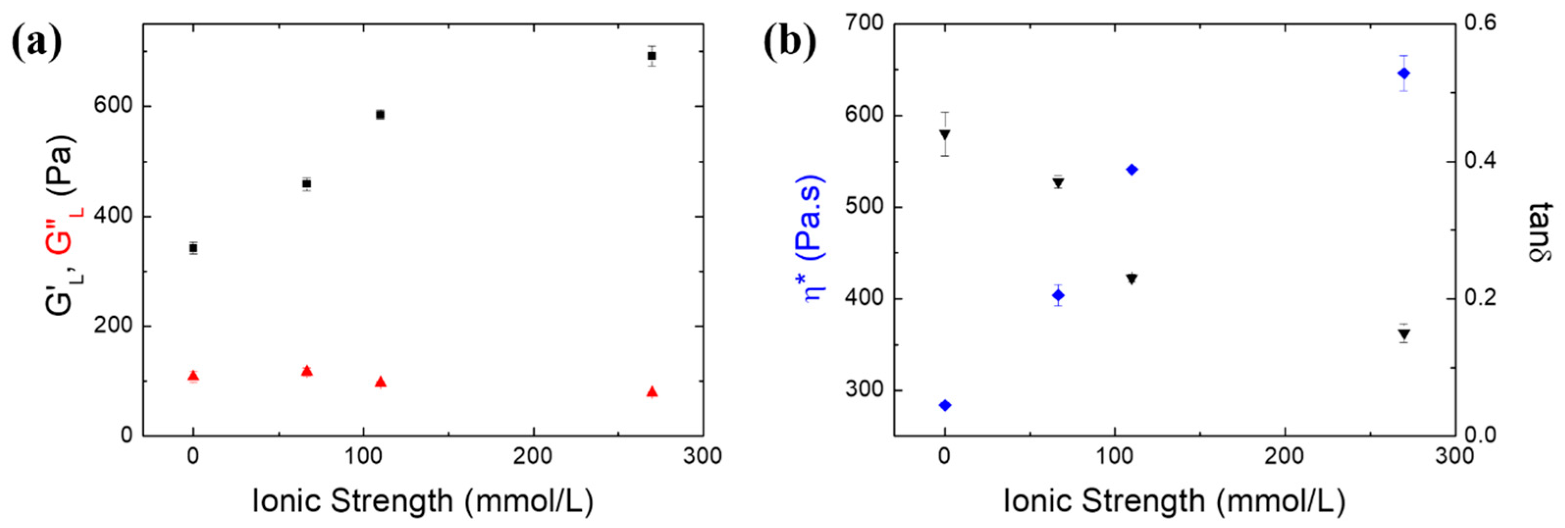
3.2. Effect of Ionic Strength on Froth Rheology

Coal particles have negatively charged surfaces which must be balanced locally by counterions in the adjacent solution to maintain overall electroneutrality [30]. The region adjacent to a charged surface is classically treated as a double layer [31]. When charged coal particles approach each other, their surface-induced electric potential fields and associated diffuse layers interact, creating a repulsive force that can overcome the attractive van der Waals force and keep the particles separated [32]. The ionic strength can affect the force between the particles by modifying the electrical double layer [33].
The rheological properties of the coal froths were investigated in samples of water with different ionic strengths. Figure 5a presents the dependence of the storage modulus G′, measured in the linear region, on the ionic strength. With an increase in the ionic strength, G′L enhanced but G″L decreased, which meant that the force needed to deform the froth increased and the energy loss during the restoration of the froth decreased. In addition, the complex viscosity η* and tanδ of the coal froths in water samples of different ionic strengths at an angular frequency of 1 rad/s were compared (Figure 5b). Obviously, the higher the ionic strength was, the more viscous the froth was. In addition, tanδ decreased with an increase in the ionic strength, meaning that the froths became more elastic and more solid-like with an increase in the ionic strength.
The effect of ionic strength on the electrical double layer can be explained via the Debye length (κ−1), which is the distance at which a charged particle shows an electrostatic effect, as shown in Equation (2) [34]:
k 1 = ε ε 0 k B T 2 N A e 2 I
where ε is the permittivity of the water, ε0 is the permittivity of free space, kB is the Boltzmann constant, T is the absolute temperature, e is the Coulomb electronic charge, and NA is Avogadro’s number; the electrical double layer k−1 decreases inversely as the square root of the ionic strength I−1/2 [35].
The thickness of the diffuse double layer reduced with an increase in the ionic strength. With an increase in the ionic strength, the ions screened charges on the surfaces of the coal particles. As shown in Figure 6a, the Zeta potential of the coal particles increased with an increase in the ionic strength, which illustrates that the negative charges on the coal particles decreased. The coal surface was negatively charged, and the counter ions in the diffusive layer were cations. With an increase in the salinity of the water, an increasing number of cations in the diffusive layer entered the Stern layer, reducing the thickness of the electrical double layer and neutralizing the surface charge [36]. The electrostatic repulsion between coal particles whose surface charges were neutralized would be reduced. Additionally, the hydrophobic attraction increased with the increasing ionic strength [31]. Thereby, the increase in particle attraction led to particle aggregation. The consequence of particle aggregation was an increase in viscosity (Figure 5b); as a result, the drainage of the froths became slow [37]. Froth stability would be improved by retarding drainage [38]. The storage modulus G′ qualitatively indicated the froth stability, so an increase in the froth stability caused by the ionic strength would explain the increase in G′ in Figure 5a.
To verify the aggregation of the particles, a cryo-SEM analysis of the coal froths was performed. Cryo-scanning electron microscopy (cryo-SEM) involves the rapid freezing and maintaining of the sample at an ultra-low temperature so that detailed surface imaging can be conducted with a scanning electron beam. Cryo-SEM provides information on air and water spaces, which remedies the shortage that a water sample cannot perform in a traditional SEM [27,39]. Cryo-SEM can provide information on the aggregation of coal particles in the froth. Figure 7 shows the cryo-SEM results for coal froths made from water samples with different ionic strengths. It displays the different states of particle aggregation. The single particles in coal froths made from deionized water and type I saline water can be observed clearly. A large electrostatic repulsion between the coal particles was needed to separate them when they were in deionized water and type I saline water. Along with an increase in ionic strength, the boundaries between the particles became increasingly blurred, which was caused by the compression of the electrical double layers and the neutralization of the negative charges on the surfaces of the coal particles. The hydrophobic attractive force between the particles became dominant when the coal particles were in type II and III water, which led to the aggregation of the particles [40,41].

4. Discussion

As the main character of the froth’s structure, solid loading was critical to the froth’s stability [42]. In this study, the solid fraction Φ was employed to evaluate the number of particles loaded in the froth, which was defined as the ratio of the mass of the solid coal particles to the total mass of the coal froths. The solid fractions of coal froths made from water samples with different ionic strengths were measured. As shown in Figure 6b, the solid fraction in the froth increased with the ionic strength. Coal particles coated on the air–water interface acted as armor for the froth, which increased the froth’s stability. With an increase in the ionic strength, more particles were attached on the bubbles’ surfaces, and the particle interaction increased, so the armoring effect of the particles on the froth became stronger.
The effect of ionic strength on the structure of the coal froth is illustrated in Figure 8. With an increase in the ionic strength, the surface charges on the surfaces of the coal particles were neutralized, so the dominate force between the coal particles in the froth changed from an electrostatic repulsive force to a hydrophobic attractive force. The decrease in the electrical double layer promoted the interaction of particles on lamellae, which resulted in an increase in the armor thickness of the froth. As a result, the energy needed to deform the froth (value of G′), as well as the froth’s stability, increased with the ionic strength.

5. Conclusions

The oscillatory rheological properties of three-phase coal froths were investigated in this study, showing that the coal froths were shear-thinning viscoelastic materials whose elastic modulus (G′) dominated their viscous modulus (G″). The particle interactions in the froths were strong, and the energy needed to deform the froths was high. The rheological properties of the coal froths generated from samples of water with different ionic strengths were compared. The elastic modulus G′L and complex viscosity η* increased, and the viscous modulus G″L and tanδ decreased with the ionic strength. The value of G′ represented the froth’s stability, and the froth’s stability also increased with the ionic strength. An increased ionic strength neutralized the negative charges on the surfaces of the coal particles, and the dominant particle interaction changed from an electrostatic repulsive force to a hydrophobic attractive force, which led to the aggregation of coal particles on the surfaces of bubbles, which was verified via Cryo-SEM, so the particle fraction in the coal froth also increased with the ionic strength. As the result, the number of particles attached to the lamellae in the froth increased with a stronger attraction, which explains the increase in the froth’s G′ value and froth stability with the ionic strength well.

Author Contributions

Conceptualization, N.Z.; methodology, N.Z.; validation, J.K., C.S. and Y.Z.; formal analysis, N.Z.; investigation, N.Z.; resources, N.Z.; data curation, N.Z.; writing—original draft preparation, N.Z.; writing—review and editing, Y.Z.; visualization, N.Z.; supervision, J.K. and C.S.; project administration, Y.Z.; funding acquisition, N.Z. All authors have read and agreed to the published version of the manuscript.

Funding

This research was funded by the China Postdoctoral Science Foundation (2022M710357) and the Open Foundation of State Key Laboratory of Mineral Processing (BGRIMM-KJSKL-2022-15).

Data Availability Statement

The data presented in this study are available upon request from the corresponding author.

Conflicts of Interest

The authors declare no conflict of interest.

References

  1. Tao, D. Recent advances in fundamentals and applications of nanobubble enhanced froth flotation: A review. Miner. Eng. 2022, 183, 107554. [Google Scholar] [CrossRef]
  2. Chen, J.; Ge, M.; Li, L.; Zheng, G. Material Transport and Flow Pattern Characteristics of Gas–Liquid–Solid Mixed Flows. Processes 2023, 11, 2254. [Google Scholar] [CrossRef]
  3. Li, L.; Gu, Z.; Xu, W.; Tan, Y.; Fan, X.; Tan, D. Mixing mass transfer mechanism and dynamic control of gas-liquid-solid multiphase flow based on VOF-DEM coupling. Energy 2023, 272, 127015. [Google Scholar] [CrossRef]
  4. Farrokhpay, S. The importance of rheology in mineral flotation: A review. Miner. Eng. 2012, 36–38, 272–278. [Google Scholar] [CrossRef]
  5. Zhang, N.; Chen, X.; Peng, Y. Effects of froth properties on dewatering of flotation products–A critical review. Miner. Eng. 2020, 155, 106477. [Google Scholar] [CrossRef]
  6. Liang, L.; Li, Z.; Peng, Y.; Tan, J.; Xie, G. Influence of coal particles on froth stability and flotation performance. Miner. Eng. 2015, 81, 96–102. [Google Scholar] [CrossRef]
  7. Xing, Y.; Gui, X.; Cao, Y.; Wang, Y.; Xu, M.; Wang, D.; Li, C. Effect of compound collector and blending frother on froth stability and flotation performance of oxidized coal. Powder Technol. 2017, 305, 166–173. [Google Scholar] [CrossRef]
  8. Xu, M.; Xing, Y.; Jin, W.; Li, M.; Cao, Y.; Gui, X. Effect of diesel on the froth stability and its antifoam mechanism in fine coal flotation used MIBC as the frother. Powder Technol. 2020, 364, 183–188. [Google Scholar] [CrossRef]
  9. Wei, Y.; Peng, Y. Effect of froth stability on dewatering of coal flotation concentrates. Miner. Process. Extr. Metall. 2015, 124, 167–174. [Google Scholar] [CrossRef]
  10. Liu, S.; Chen, X.; Peng, Y. Deaeration of stable coal froth by surfactants to modify the interfacial properties. Fuel 2021, 298, 120839. [Google Scholar] [CrossRef]
  11. Liu, S.; Chen, X.; Peng, Y. Destabilising persistent coal froth using silicone oil. Int. J. Min. Sci. Technol. 2021, 31, 1023–1031. [Google Scholar] [CrossRef]
  12. Mezger, T.G. The Rheology Handbook: For Users of Rotational and Oscillatory Rheometers; Vincentz Network GmbH & Co KG: Vincentz Verlag Hannover/Germany, 2006. [Google Scholar]
  13. Li, C.; Runge, K.; Shi, F.; Farrokhpay, S. Effect of flotation froth properties on froth rheology. Powder Technol. 2016, 294, 55–65. [Google Scholar] [CrossRef]
  14. Li, C.; Farrokhpay, S.; Shi, F.; Runge, K. A novel approach to measure froth rheology in flotation. Miner. Eng. 2015, 71, 89–96. [Google Scholar] [CrossRef]
  15. Wang, L.; Li, C. A Brief Review of Pulp and Froth Rheology in Mineral Flotation. J. Chem. 2020, 2020, 3894542. [Google Scholar] [CrossRef]
  16. Li, C.; Runge, K.; Shi, F.; Farrokhpay, S. Effect of froth rheology on froth and flotation performance. Miner. Eng. 2018, 115, 4–12. [Google Scholar] [CrossRef]
  17. Gunasekaran, S.; Ak, M.M. Dynamic oscillatory shear testing of foods—Selected applications. Trends Food Sci. Technol. 2000, 11, 115–127. [Google Scholar] [CrossRef]
  18. Hyun, K.; Wilhelm, M.; Klein, C.O.; Cho, K.S.; Nam, J.G.; Ahn, K.H.; Lee, S.J.; Ewoldt, R.H.; McKinley, G.H. A review of nonlinear oscillatory shear tests: Analysis and application of large amplitude oscillatory shear (LAOS). Prog. Polym. Sci. 2011, 36, 1697–1753. [Google Scholar] [CrossRef]
  19. Cruz, N.; Peng, Y. Rheology measurements for flotation slurries with high clay contents—A critical review. Miner. Eng. 2016, 98, 137–150. [Google Scholar] [CrossRef]
  20. Cohen-Addad, S.; Krzan, M.; Hohler, R.; Herzhaft, B. Rigidity percolation in particle-laden foams. Phys. Rev. Lett. 2007, 99, 168001. [Google Scholar] [CrossRef]
  21. Dollet, B.; Raufaste, C. Rheology of aqueous foams. Comptes Rendus Phys. 2014, 15, 731–747. [Google Scholar] [CrossRef]
  22. Nikolai, D.; Denkov, S.S.T. Reinhard Höhler, Sylvie Cohen-Addad, Foam Rheology. In Foam Engineering: Fundamentals and Applications; Stevenson, P., Ed.; John Wiley & Sons, Ltd.: Hoboken, NJ, USA, 2012. [Google Scholar]
  23. Zhang, N.; Chen, X.; Nicholson, T.; Peng, Y. The effect of froth on the dewatering of coals—An oscillatory rheology study. Fuel 2018, 222, 362–369. [Google Scholar] [CrossRef]
  24. Zhang, N.; Chen, X.; Peng, Y. The interaction between kaolinite and saline water in affecting the microstructure, rheology and settling of coal flotation products. Powder Technol. 2020, 372, 76–83. [Google Scholar] [CrossRef]
  25. Zhang, N.; Chen, X.; Nicholson, T.; Peng, Y. The effect of saline water on the settling of coal slurry and coal froth. Powder Technol. 2019, 344, 161–168. [Google Scholar] [CrossRef]
  26. Solomon, T. The Definition and Unit of Ionic Strength. J. Chem. Educ. 2001, 78, 1691. [Google Scholar] [CrossRef]
  27. Aston, R.; Sewell, K.; Klein, T.; Lawrie, G.; Grøndahl, L. Evaluation of the impact of freezing preparation techniques on the characterisation of alginate hydrogels by cryo-SEM. Eur. Polym. J. 2016, 82, 1–15. [Google Scholar] [CrossRef]
  28. Farrokhpay, S. The significance of froth stability in mineral flotation—A review. Adv. Colloid. Interface Sci. 2011, 166, 1–7. [Google Scholar] [CrossRef]
  29. Yu, Y.; Ma, L.; Cao, M.; Liu, Q. Slime coatings in froth flotation: A review. Miner. Eng. 2017, 114, 26–36. [Google Scholar] [CrossRef]
  30. He, X.; Liu, X.; Song, D.; Nie, B. Effect of microstructure on electrical property of coal surface. Appl. Surf. Sci. 2019, 483, 713–720. [Google Scholar] [CrossRef]
  31. Hu, Y.; Guo, T.; Ye, X.; Li, Q.; Guo, M.; Liu, H.; Wu, Z. Dye adsorption by resins: Effect of ionic strength on hydrophobic and electrostatic interactions. Chem. Eng. J. 2013, 228, 392–397. [Google Scholar] [CrossRef]
  32. Mercer, K.L.; Tobiason, J.E. Removal of Arsenic from High Ionic Strength Solutions: Effects of Ionic Strength, pH, and preformed versus in situ formed HFO. Environ. Sci. Technol. 2008, 42, 3797–3802. [Google Scholar] [CrossRef]
  33. Piret, F.; Su, B.L. Effects of pH and ionic strength on the self-assembly of silica colloids to opaline photonic structures. Chem. Phys. Lett. 2008, 457, 376–380. [Google Scholar] [CrossRef]
  34. Tadmor, R.; Hernández-Zapata, E.; Chen, N.; Pincus, P.; Israelachvili, J.N. Debye Length and Double-Layer Forces in Polyelectrolyte Solutions. Macromolecules 2002, 35, 2380–2388. [Google Scholar] [CrossRef]
  35. Cho, J.; Heuzey, M.-C.; Bégin, A.; Carreau, P.J. Viscoelastic properties of chitosan solutions: Effect of concentration and ionic strength. J. Food Eng. 2006, 74, 500–515. [Google Scholar] [CrossRef]
  36. Chang, Z.; Chen, X.; Peng, Y. The effect of saline water on the critical degree of coal surface oxidation for coal flotation. Miner. Eng. 2018, 119, 222–227. [Google Scholar] [CrossRef]
  37. Binks, B.P.; Horozov, T.S. Aqueous foams stabilized solely by silica nanoparticles. Angew. Chem. 2005, 117, 3788–3791. [Google Scholar] [CrossRef]
  38. Wang, J.; Nguyen, A.V.; Farrokhpay, S. A critical review of the growth, drainage and collapse of foams. Adv. Colloid Interface Sci. 2016, 228, 55–70. [Google Scholar] [CrossRef]
  39. Wightman, R. An Overview of Cryo-Scanning Electron Microscopy Techniques for Plant Imaging. Plants 2022, 11, 1113. [Google Scholar] [CrossRef]
  40. Manono, M.S.; Corin, K.C.; Wiese, J.G. The effect of ionic strength of plant water on foam stability: A 2-phase flotation study. Miner. Eng. 2013, 40, 42–47. [Google Scholar] [CrossRef]
  41. Wang, B.; Peng, Y. The effect of saline water on mineral flotation—A critical review. Miner. Eng. 2014, 66–68, 13–24. [Google Scholar] [CrossRef]
  42. Barbian, N.; Hadler, K.; Ventura-Medina, E.; Cilliers, J.J. The froth stability column: Linking froth stability and flotation performance. Miner. Eng. 2005, 18, 317–324. [Google Scholar] [CrossRef]
Figure 1. The size distribution of the coal particles. The cumulative volume and volume density are shown as black solid and red dashed curves, respectively. The size of 80% particles was indicted by the black dash line.
Processes 11 02569 g001
Figure 2. The results of time-dependent sweeps of the coal froths made from type I water. Storage G′ (■) and loss G″ () moduli were plotted as functions of time. The angular frequency was 2 rad/s, and the oscillatory strain was 0.3%. The dotted line indicates the time at which subsequent amplitude and frequency sweeps were performed.
Processes 11 02569 g002
Figure 3. The results of the amplitude sweeps of the coal froths made from type I saline water. G′ (■, □) and G″ (, ) were plotted as functions of the oscillation strain amplitude. The curves comprising solid symbols (■, ) are the results measured from 0.01% to 1%, and the curves comprising hollow symbols (□, ) are the results measured from 1% to 0.01%. The vertical dash line separates the linear and nonlinear regions. The angular frequency was 2 rad/s.
Processes 11 02569 g003
Figure 4. The results of frequency sweeps of the coal froths made from type I saline water. The storage modulus G′ (■), loss modulus G″ (), and complex viscosity η* () were plotted as functions of the angular frequency. The oscillatory strain was 0.3%.
Processes 11 02569 g004
Figure 5. (a) The dependence of the storage modulus G′L (■) and loss modulus G″L () on the ionic strength. The values of G′L and G″L were the average of the G′ and G″ values in the linear region of the amplitude sweeps, respectively. The angular frequency was 2 rad/s. (b) The distribution of tanδ (tanδ = G″/G′) (▼) and complex viscosity η* () measured at angular frequency ω = 1 rad/s for the four different types of water. The shear strain was 0.03%.
Processes 11 02569 g005
Figure 6. (a) The Zeta potential for coal particles in different water samples at a pH of 7; (b) the distribution of the solid fraction for the four different types of water.
Processes 11 02569 g006
Figure 7. Cryo-SEM of coal froths made from deionized (a), type I saline (b), type II saline (c), and type III saline (d) water. The scale bar is 5 µm.
Processes 11 02569 g007
Figure 8. The effect of ionic strength on the structure of the coal froth.
Processes 11 02569 g008
Table 1. The compositions of the four kinds of water used in this study. The units of concentration of the ions and the ionic strength are both mmol/L.
Type Ca2+Mg2+Na+K+HCO3−SO42−ClIonic Strength
DI water0.000.000.000.000.000.000.000.00
Saline water I2.254.9033.170.379.5811.7214.8166.70
Saline water II4.509.7966.340.7419.1623.4429.62109.95
Saline water III9.0019.58132.691.4938.3346.8859.24269.80
Disclaimer/Publisher’s Note: The statements, opinions and data contained in all publications are solely those of the individual author(s) and contributor(s) and not of MDPI and/or the editor(s). MDPI and/or the editor(s) disclaim responsibility for any injury to people or property resulting from any ideas, methods, instructions or products referred to in the content.

