1. Introduction
With the development of industrial technology, achieving comprehensive performance in metal materials is increasingly demanding. A large number of methods have been proposed for the production of superior metal materials. Among them, the preparation of ultra-fine-grained (UFG) metallic materials is of particular interest [
1]. Compared with conventional materials, UFG metallic materials have excellent properties, such as high strength [
2], high toughness, high corrosion resistance [
3], high machinability, excellent strong plasticity matching, high fracture impedance [
4], etc. Moreover, some of the UFG materials have shown good super-plasticity at low temperatures and high strain rates [
5]. Due to the excellent comprehensive performance of UFG materials, the mechanism of and preparation method for UFG materials have become a research hotspot in the field of metal materials.
In the preparation of UFG materials, there are two main methods, which are the synthesis method and the grain refinement method. The synthesis method is the densification of ultra-fine powders containing atoms, molecules, ions, or nanoparticles to obtain ultra-fine microstructures, such as inert gas coalescence in situ pressurization, high-energy ball milling, amorphous crystallization, and melt solidification. Although these synthetic methods are relatively straightforward for the preparation of UFG materials, the materials prepared by these methods suffer from defects, such as poor densification and susceptibility to contamination [
6]. The grain refinement method directly converts the original coarse grains into ultra-fine grains, effectively avoiding the shortcomings of the synthetic method. Severe plastic deformation (SPD) is one of the grain refinement methods and involves directly refining large grains within the material to the nanometer or sub-micron size by means of huge plastic deformation. Compared with other UFG material preparation methods, SPD can be used to prepare large-size UFG materials and achieve a more uniform microstructure. In addition, SPD is well connected with the existing material preparation and processing technology and equipment [
7]. Since Segel [
8] proposed the equal channel angular pressing (ECAP) method in the 1980s, SPD has received a great deal of attention from material researchers all over the world.
The mechanism of grain refinement is an important field of SPD research. Several grain refinement mechanisms have been proposed, such as the dislocation deformation mechanism [
9], twinning deformation mechanism [
10], and grain boundary slip and torsion deformation mechanism [
11]. Although the dislocation deformation mechanism is accepted by most scholars, its applicability is still controversial. Another important area of research on SPD is the development of techniques to realize the intense plastic deformation of metals. Since SPD was first introduced as an effective approach to produce UFG metals in the 1980s [
8,
12], tremendous efforts have been exerted to develop SPD techniques, such as equal channel angle pressing (ECAP) [
13,
14], high-pressure torsion (HPT) [
15,
16], accumulated roll bonding (ARB) [
17,
18], multi-directional forging (MDF) [
19,
20], cyclic extrusion compression (CEC) [
21,
22], repetitive corrugation and straightening (RCS) [
23,
24], twist extrusion (TE) [
25,
26], constrained groove pressing (CGP) [
27,
28], and so on.
Although a large number of SPD techniques have been proposed, the quality of the UFG materials prepared with these methods is not yet stable. In addition, these methods have high requirements for extrusion equipment and molds, which limits their large-scale industrial application. The development of novel SPD methods remains an important direction of research in the field of UFG material preparation. Paydar [
29] developed a composite SPD method named equal channel angular pressing—forward extrusion (ECAP-FE). The results showed that, compared to the conventional extrusion process, the ECAP-FE method not only prevents surface cracking in the workpiece but also improves the microstructure and mechanical properties of the material. Shamsborhan [
30] proposed the planar twist channel angular extrusion (ECAP-SSE) method and successfully produced pure copper samples with a nano-sized microstructure. The results showed that the yield strength, ultimate tensile strength, and hardness values of the pure copper after extrusion increased by 71%, 69%, and 113%, respectively. Sepahi-Boroujeni [
31] proposed the expansion equal channel angular extrusion (E-ECAP) technology. The results of extrusion tests on pure aluminum samples showed that, after the first pass of the E-ECAE process, the yield stress and hardness of aluminum increased by about 300% and 50%, respectively. Additionally, double change channel angular pressing (DCCAP) [
32] and unequal channel angular pressing (UCAP) [
33] have been proposed and successfully applied in the preparation of ultra-fine grains with magnesium alloys.
Direct extrusion is capable of producing enormous strain in a workpiece, making it a potential method for preparing UFG materials. The possibility of using direct extrusion to produce UFG materials has been previously investigated [
34,
35]. It has been demonstrated that, under the conditions of high-ratio extrusion (HRE) [
36] or hydrostatic extrusion [
37], favorable results in grain refinement can be obtained. Additionally, Zaharia proposed the new method of multiple direct extrusion (MDE) [
34]. Compared to other SPD methods, the strain gradient in the cross-section of the MDE specimen was large, which is very favorable for grain refinement. However, most of the proposed extrusion techniques showed difficulties in extruding repeatedly with the same die. In addition, the uniformity of strain distribution inside the workpieces after extrusion was poor [
7,
38,
39].
Based on conventional direct extrusion, this paper proposes a new SPD method called asymmetric gradient extrusion (AGE) to produce UFG bulk materials. Compared with the conventional extrusion process, this new SPD technique can realize a much more uniform strain distribution. The deformation characteristics of the workpiece with AGE were theoretically analyzed using the slip line field. In addition, finite element analysis was used to verify the theoretical results. Moreover, the effects of AGE on the microstructure of annealed pure copper samples were experimentally investigated. Finally, the advantages and mechanism of this SPD technique in producing UFG materials are highlighted and discussed.
2. Principle of Asymmetric Gradient Extrusion
The geometry of the die channel is symmetrical in most extrusion cases. Accordingly, the deformed zones are formed symmetrically in the workpiece and the desired reduction in the workpiece cross-section can be achieved. However, the variation in the workpiece cross-section makes it very difficult to re-extrude the workpiece with the same die, which is basically required in SPD of bulk workpieces. Some changes were made in AGE to solve this problem. First, the cross-section of the die channel and the initial billet are both designed with a rectangular profile, as shown in
Figure 1a. As a result, the deformation of the workpiece in the channel can be approximated as a case of plane strain. An illustration of the AGE process is shown schematically in
Figure 1b. The thickness of the initial billet is constrained to be equal to the width of the channel outlet to ensure that the shape of the workpiece remains unchanged after extrusion. As shown in
Figure 1b, the extruded part has the same shape and dimensions as its initial counterpart. In this way, repeated extrusion of the part can be achieved and a targeted strain in the part can be achieved with multiple extrusion passes.
The asymmetrical distribution of two extrusion bevels in the channel, which are generally symmetrical by design in conventional extrusion, is another modification introduced in AGE. A vertical distance h, which has great influence on the deformation behavior of the workpiece during extrusion, is arranged between the two extrusion bevels. Accordingly, two deformation zones (DZs) can be formed in AGE, and the parameter h defines the independence or interaction of these two DZs. In addition to h, the angles α and β of the two extrusion bevels can also be assigned independently. The characteristics of the deformation fields around the two extrusion bevels are strongly related to these two parameters. All of the above parameters should be carefully assigned with the aim of realizing a high and uniform strain field in the workpiece during the extrusion process.
3. Mechanism of Grain Fragmentation in AGE
According to the characteristics of metal flow in the die channel, the workpiece can be divided into five parts, which are schematically illustrated in
Figure 2. In region I, the material, which is assumed to be rigid, moves downward with a constant velocity
VI, which is equal to the punch velocity. The material undergoes plastic deformation in region II and region IV. Depending on the value assigned to parameter
h, the two deformation regions II and IV can interact in region III or be totally independent. However, to realize our goal, the parameter
h should be large enough to separate the two plastic deformation regions. Therefore, the material in region III has a rigid flow. In region
V, the material moves to the exit of the die with constant velocity
VV without any further deformation. The volume of the material does not change before and after extrusion, so the speed relationship of the material in region V and region
I can be expressed as
VV = (b/a)
VI. Region II is the first deformation zone, which is separated from region I and region III by the entry and existing surfaces Γ
1 and Γ
2. They belong to the slip line field of the first deformation zone (DZ-1) and correspond to the beginning and end of deformation. Similarly, Γ
3 and Γ
4 are the entry and existing surfaces of the second deformation zone (DZ-2), which belong to the slip line field of DZ-2.
Slip line field (SLF) analysis is a traditional theoretical method for analyzing metal-forming characteristics. With the SLF solution, the extrusion mechanism through a wedge-shaped die has been well studied by many scholars [
19,
25]. Due to the similarity of die apertures, the SLF of AGE can be deduced, as is shown in
Figure 3. As discussed above, two independent deformation zones (DZs) should be formed in AGE and, correspondingly, there are two isolated SLFs distributed along the vertical direction of the die channel.
As shown in
Figure 3, the vertical distribution of these two SLFs reveals that the parameter
h largely defines the behavior between these two DZs. In order to form two independent DZs, a large value should be used for
h. Due to the SLFs of these two DZs having very similar characteristics, only the SLF of DZ-1 is discussed in detail below. The geometry of the DZ-1 slip line configuration is defined by the field angles
λ1,
φ1, and
θ1 and the die angle
α. The value of
λ1 is dependent on the friction condition at the interface between the die and the work material. For a frictionless condition, the value of
λ1 equals π/4. The parameter
φ1 reflects the range of reductions for which the field is valid. When the extrusion ratio tends to its maximum value (for which
θ1 = 0), the SLF tends to its limit. When
θ1→0, the point E
1→D
1 and the point C
1→F
1 so that the slip line field A
1E
1C
1F
1B
1 can be approximated with a triangular one A
1B
1C
1. The kinematically admissible velocity field associated with the SLF from DZ-1 becomes a triangular velocity field, as shown in
Figure 4a. In this field, the material moves parallel to the inclined wall with velocity
Va. At each point on the surfaces Γ
1 and Γ
2, the velocities
VI and
Va suddenly change the direction.
For an arbitrary point P on AC, its corresponding point on BC is Q. As shown in
Figure 2, the velocity at point P is affected by both the region I velocity
VI and the region II velocity
Va. The velocity decomposition of
VI and
Va along the AC tangential and normal directions is shown in
Figure 4a. Due to the continuity of metal flow,
VI and
Va on the AC normal direction must be equal; that is,
Van_AC =
VIn. However, as illustrated in
Figure 4a, the velocities of
VI and
Va on the AC tangential direction have different values,
Vat_AC >
VIt. The differences between
Vat_AC and
VIt define the velocity discontinuities, giving rise to tangential stress
τAC. Similarly, the velocity decomposition of the region II velocity
Va and region III velocity
VIII in the BC normal and tangential directions at point Q on BC is also displayed in
Figure 4a. In addition, the velocity
Vat_BC and
VIIIt in the BC tangential direction are also different. Therefore, a stress
τBC along the BC tangential direction is formed at point Q.
The tangential stress distribution on the boundary of the two deformation zones in AGE is schematically illustrated in
Figure 4b. When an elongated and thin-enough grain (obtained from a previous AGE pass) crosses one velocity discontinuity surface along which the tangential stress exceeds the strength in pure shear (τ > k), the grain strength is overcome and the fragmentation process starts. Accordingly, the speed-discontinuous surface plays an important role in grain fragmentation. The larger the number of discontinuous surfaces, the more effective the fragmentation is. Compared with traditional extrusion, AGE forms two independent DZs, increasing the number of discontinuous surfaces. Moreover, the shear stresses on the discontinuous surfaces of the two DZs are complementary. The uniformity of the shear stress formed by AGE is greatly enhanced.
4. Finite Element Analysis
In order to validate the analysis results discussed in
Section 3, the finite element method was used to study the deformation characteristics in AGE. The simulation models were set up according to the geometry parameters shown in
Figure 1, the values of which are listed in
Table 1. Here, the influence of the parameters
h and
β was emphasized because they greatly affect the deformation zone formed in the die channel. Conventionally, model one was direct extrusion, as the value of parameter
h was set to 0. Two AGE simulation models, models two and three, were established to emphasize the different deformation mechanisms compared with model one and the influence of parameter
h.
All simulations were performed using the commercial finite element software DEFORM-3D. The dies and punches were set as rigid. In addition, an elastic-plastic material model was assigned to the pure copper bulk workpieces. The frictional behavior between the workpiece and the die channel was considered with a shear friction model and assigned a coefficient of 0.12. The same extrusion speed of 1 mm/s was used for the punch in all simulation models. During the simulation, the workpieces were pushed down by the punch along the die channel. In all the simulation models, the workpieces were discretely divided by the tetrahedral meshes. The initial maximum mesh size was 0.26 mm and the automatic re-meshing technique was used during the simulation process.
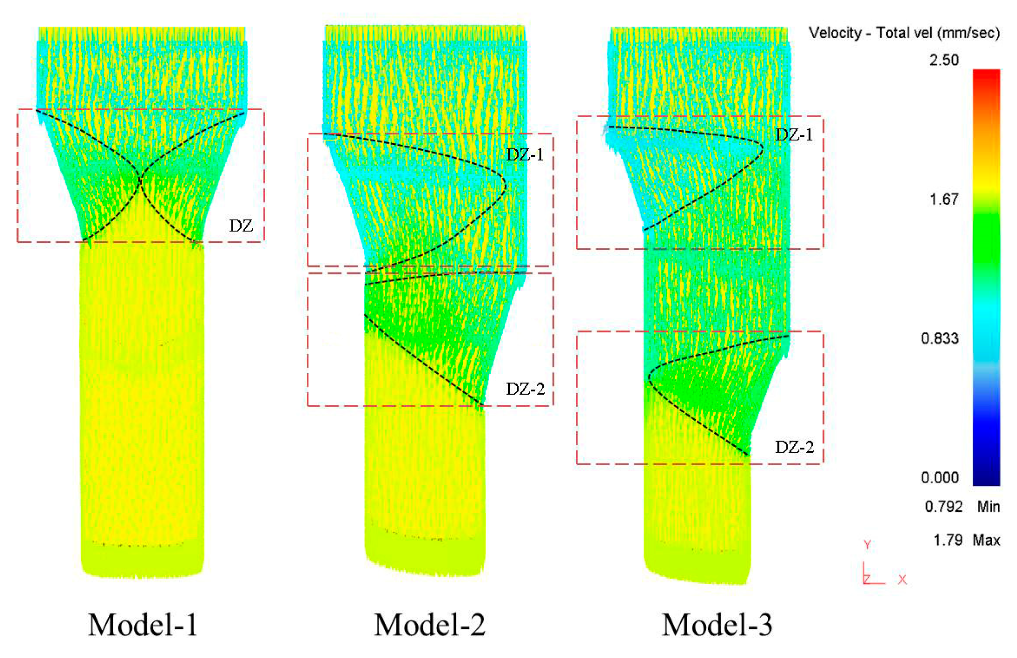
The velocity field results for the workpieces in the three simulation models are shown in
Figure 5. Compared with model one, which was a traditional direct extrusion method, more deformation-zone areas were formed in the AGE method, as is clearly shown in models two and three. The larger
h was, the more deformation-zone areas were generated. This indicates that the extreme deformation in direct extrusion can be largely smoothed in AGE. In addition, along the punch-moving direction, one deformation zone in direct extrusion was transformed into two deformation zones. Moreover, when a higher value was assigned to
h, such as in model three, two independent deformation zones could be generated in the die channel. This provides an amazing strategy to obtain a more even strain field in a bulk workpiece through compensation by the two independent deformation zones.
The slip line field in the workpiece can be reflected by the equivalent strain rate, which is schematically illustrated in
Figure 6. According to the results, high strain rates were generated at the entrance and exit of each deformation zone. In addition, two independent strain rate zones were formed in model three, which was the result of the velocity field, as shown in
Figure 5. The simulation results for the strain rate were very similar to the slip line field discussed in
Section 2, which supports the theoretical analysis results. Correspondingly, coarse grains can be more effectively refined to a smaller size in AGE, especially under the condition where two independent deformation zones are formed, as shown in model three.
For model three, the results for the workpiece geometry variation during extrusion were extracted by tracking the mesh morphology, as schematically illustrated in
Figure 7. It was found that, in the first deformation zone, the bulk workpiece was mainly subjected to shear strain by the tangential forces. As the workpiece was extruded into the second deformation zone, the meshes gradually elongated. Numerically, the maximum shear strains of the mesh were 0.82 and 1.13 in the first and second deformation zones, respectively. This indicates that the workpiece was shaped by the combined effect of shear and tensile forces. The shear effect, which is the driving force for grain fragments, was dominant in the two deformation zones.
5. Experimental Analysis
The deformation characteristics and microstructure of bulk samples treated with AGE were verified experimentally. All the bulk samples were made of pure copper and fabricated into bulk shape with dimensions of 15 × 15 × 25 mm. Prior to extrusion, all the samples were annealed to remove the influence of residual stress. A typical AGE die was used with the parameters = 19°, = 21°, and h = 30 mm. In addition, the MoS2 lubricant was sprayed on samples and die to reduce the frictional effect. All the simulation models were performed at a ram speed of 20 mm/min for the punch at room temperature.
In order to investigate the deformation characteristics of the samples in the die channel, rectangular grids were sprayed on the surfaces of all samples. The deformed shape of the samples in the die channel is shown in
Figure 8. It was clearly verified that two deformation zones can be formed in AGE. In addition, the variation in the rectangular grids on the sample surface was very consistent with the results for the mesh shape from the simulation. The theoretical and simulation results discussed in the above sections were verified.
The microstructure variation in the multi-pass AGE was examined using optical microscopy, the results of which are shown in
Figure 9. In addition, the grain size statistics results, which were extracted using the open-source image processing software ImageJ 1.53v, are also shown. It was obvious that the grain size was dramatically refined with the increase in the number of passes with AGE. The original grain size of annealed samples was 86 μm on average. Meanwhile, the shape of the grain cross-section was dominated by isometric polygons. After two passes of AGE, the average grain size was reduced to 16 μm, and fibrous grains were mainly produced. By increasing the number of extrusion passes, an average grain size of 1.3 μm and 0.6 μm could be achieved with four and six passes, respectively. In addition, the grain size distribution was simultaneously concentrated, which means more uniform grains can be obtained. The grain size variation results indicated that AGE is a promising SPD method for the preparation of UFG materials. In conclusion, the AGE method not only produces small grains but also a uniform grain size distribution.
7. Conclusions
In this paper, a new method for the preparation of UFG materials named asymmetric gradient extrusion (AGE) was introduced. It was shown that AGE is of great advantage in the preparation of UFG bulk materials. The deformation characteristics of workpieces in AGE were analyzed using the slip line field and finite element method, and an experiment was conducted to verify the theoretical analysis. Some conclusions can be drawn as follows.
(1) Unlike traditional direct extrusion, AGE can form two independent deformation zones in its die channel. In addition, the two deformation zones are complementary, making it possible to achieve a uniform strain field in the workpiece. The distance between the two deformation zones is an important parameter. If this distance is set to a small value, the two deformation zones interact with each other, which greatly affects the uniformity of plastic deformation in the workpiece;
(2) AGE is very effective in obtaining ultra-fine grains. After six passes of extrusion, an average size of 0.6 μm can be obtained in bulk pure copper samples. In addition, the grain size distribution is more concentrated, which means that a uniform grain size distribution can be achieved. The grain size variation results indicate that AGE is a promising SPD method for producing UFG materials;
(3) The mechanism of grain fragmentation in AGE can be easily explained by dislocation models. With multiple passes of AGE, high-density dislocations can be accumulated. Consequently, the dislocation walls within a coarse grain are transformed into subgrain boundaries. Finally, a much smaller grain size can be obtained.


