Article

Disturbance-Suppression Method of Direct-Driven PMSG-Based Wind Power System in Microgrids

1
College of Electrical Engineering and New Energy, China Three Gorges University, Yichang 443002, China
2
School of Electrical Engineering and Automation, Wuhan University, Wuhan 430072, China
3
School of Hydraulic and Ecological Engineering, Nanchang Institute of Technology, Nanchang 330099, China
*
Author to whom correspondence should be addressed.
Processes 2023, 11(7), 2189; https://doi.org/10.3390/pr11072189
Submission received: 12 June 2023 / Revised: 16 July 2023 / Accepted: 17 July 2023 / Published: 21 July 2023

Abstract

:
In order to solve the current fluctuation problem in microgrids, a suppression method called the Direct-driven Permanent Magnet Synchronous Generator (DPMSG)-based Wind Power System (WPS) based on an adaptive enhanced moving average filter algorithm is proposed. Firstly, the mathematical model of the WPS is established. On this basis, the suppression method under unbalanced conditions is derived by the instantaneous power equation to ensure the stable operation of the microgrid. In order to improve the dynamic compensation capability of the DPMSG-based WPS, an enhanced moving average filtering algorithm with frequency adaptability is proposed. The positive and negative sequence components are obtained in the dq frame by this filtering algorithm. Subsequently, the angular frequency of the microgrid is obtained according to the changing phase, which realizes the high-performance control of the WPS and avoids the complicated parameter adjustment of traditional methods. The correctness of this method is verified by the simulation results. The DPMSG-based WPS with the proposed method can improve the stability of the microgrid.

1. Introduction

With the development of wind power technology, the proportion of DPMSG-based WPS in the power system is gradually increasing [1,2]. However, the DPMSG-based WPS has the characteristics of dispersion, randomness and volatility, which makes the microgrid prone to three-phase asymmetry of the voltage and current, resulting in a decline in the power quality of the microgrid [3,4,5]. Therefore, a strong ability to suppress unbalanced disturbances is required in the DPMSG-based WPS connected to the microgrid [6,7]. To this end, it is necessary to accurately detect the state information in the transient process and quickly suppress disturbances by the control technology, so as to improve microgrid stability.
Many studies have been performed on the detection technology and control methods of renewable energy systems in unbalanced environments [8,9,10]. Based on the DPMSG-based WPS model, the key parameters affecting the stability of the power system are studied [11]. A model predictive controller design method is proposed for Maximum Power Point Tracking (MPPT) systems based on the DPMSG [12]. The adaptive overall control in the whole wind speed range increases the robustness of the DPMSG-based WPS [13]. The modeling and control methods of the DPMSG-based WPS are compared and analyzed, and the direction of future research is demonstrated in [14].
For the problem of synchronous information detection, the detection technology is mainly divided into the closed-loop and open-loop detection algorithms [15,16,17]. The closed-loop detection algorithms usually include the Decoupled Double Synchronous Reference Frame Phase-Locked Loop (DDSRF-PLL), the single synchronous reference frame phase-locked loop, and the second-order generalized integrator frequency-locked loop algorithms [18,19]. When the microgrid environment is harsh, the dynamic response time of these algorithms is generally longer. To solve this problem, the open-loop detection algorithm is developed in [20,21]. The open-loop detection algorithm realizes the accurate acquisition of the synchronous phase of the single-phase signal by the virtual quadrature voltage [22]. Three traditional synchronous detection algorithms are analyzed and compared [23]. Subsequently, a benchmark model is proposed to study the dynamic performance of the open-loop detection algorithm in unbalanced environments. In an unbalanced environment, phase-locked loop-free control of renewable energy systems is implemented, but this algorithm is only used for power grids with small frequency fluctuations [24]. In Table 1, a comparative analysis of state-of-the-art research is presented. From the literature in Table 1, it can be found that in the existing research it is difficult to quickly detect synchronization information with frequency changes.
An enhanced integrated control strategy is proposed for the compensation control problem in the unbalanced environment [31]. In addition, this strategy can also deal with harmonic problems. In [32], the control method can suppress the negative-sequence current in the unbalanced environment by the instantaneous symmetrical component method. A current-compensation method for photovoltaic power systems is proposed, which optimizes the control parameters by the particle swarm optimization algorithm to achieve multi-objective control [33]. The compensation method based on the flexible harmonic loop with the fundamental current control solves the unbalance problem [34]. In the harsh environment, the unbalanced voltage is compensated by an improved enhanced phase-locked loop [35]. A model predictive current controller based on Kalman filter estimator is proposed to improve the power quality of the microgrid in [36]. However, the structures of these control methods are relatively complex.
In order to achieve a compensation method with a simpler structure and faster response, this paper proposes a disturbance-suppression method for the WPS based on the adaptive enhanced moving average filter algorithm. The main work of this paper is as follows:
(1)
The mathematical model of the DPMSG-based WPS is carried out based on the circuit topology and the control strategy.
(2)
The angular frequency is calculated from the changing phase, and the accurate control of WPS is realized. Then, the command current value under unbalanced conditions is derived by the instantaneous power equation.
(3)
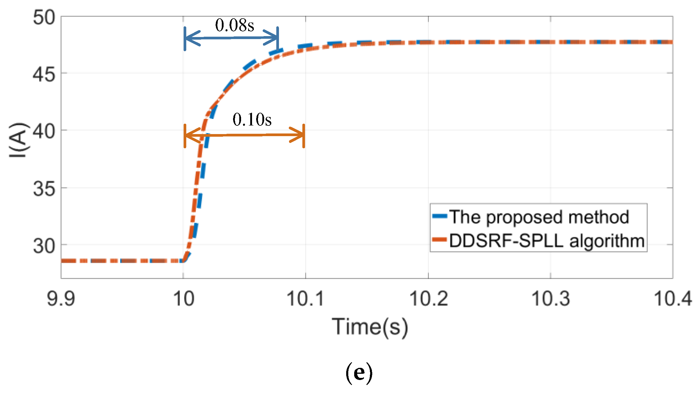
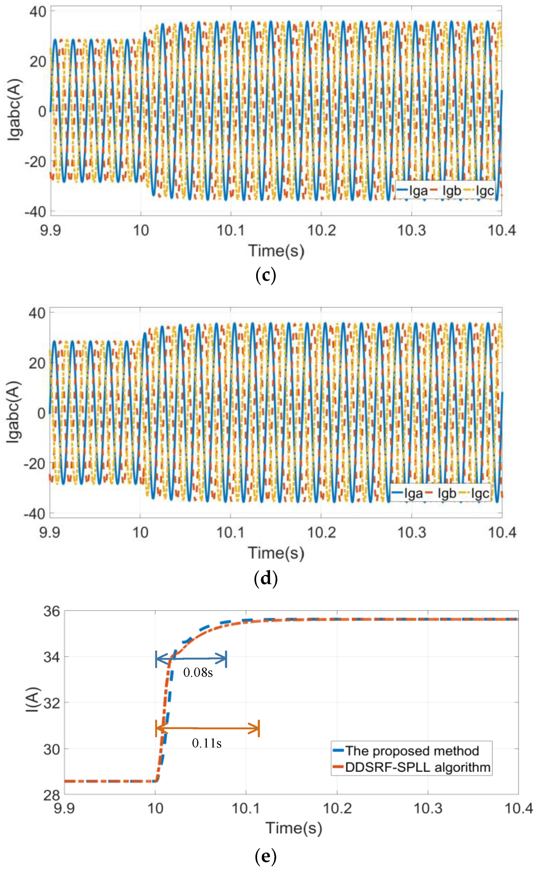
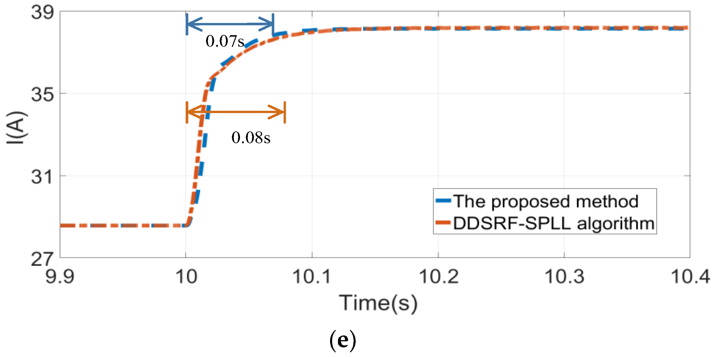
This method can significantly improve the compensation capabilities, avoids the parameter design problem of the phase-locked loop, and has a faster response speed.
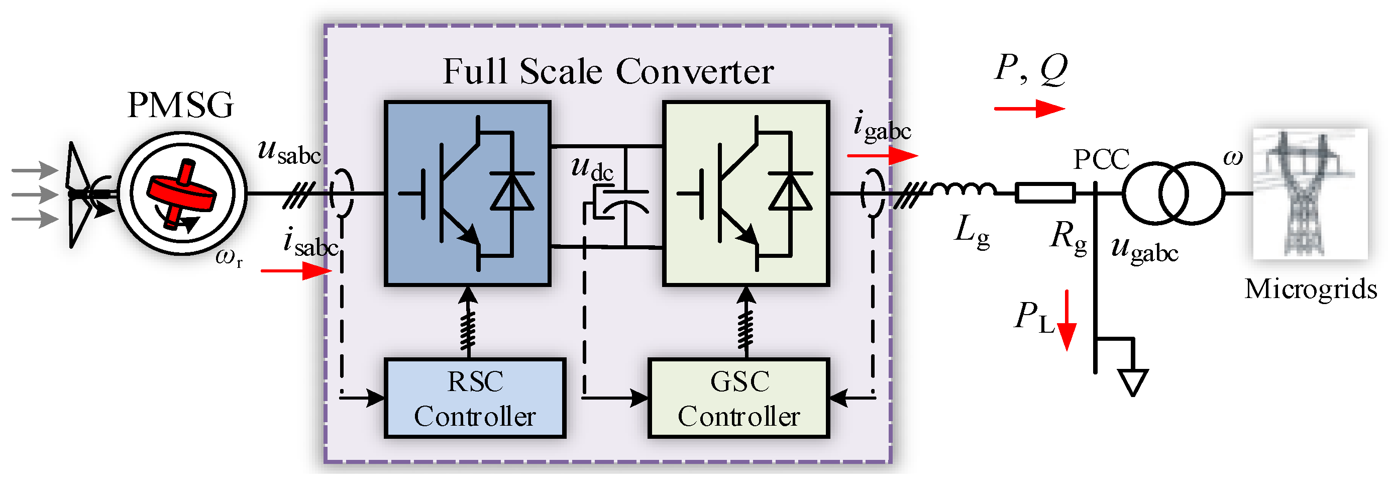
The mathematical model of the DPMSG-based WPS is introduced in Section 2. A synchronization information detection algorithm is proposed, which can realize fast and accurate detection of the synchronization phase and angular frequency in Section 3. For Section 4, the compensation method of current fluctuation is presented. The effectiveness of the proposed method is verified in Section 5.

2. DPMSG-Based WPS

The circuit topology of the DPMSG-based WPS is shown in Figure 1. This WPS is mainly composed of the synchronous generator, the inverter, the rectifier, the equivalent inductance, the equivalent resistance, the transformer and the microgrid. In the figure, ω is the real-time angular frequency of the microgrid, ωr is the wind turbine speed, isabc is the stator current, udc is the capacitor voltage, igabc is the output current of the grid-side converter, Lg and Rg are the equivalent inductance and resistance, P and Q are the active and reactive power of the DPMSG-based WPS, and PL is the power consumed by the load.

2.1. Mathematical Models of Wind Turbine and DPMSG

The wind turbine is the prime mover in the DPMSG-based WPS, which drives the DPMSG by the fan blades. The main function of the wind turbine is to realize the maximum utilization of wind energy. According to Bates theory [12], the output mechanical power can be expressed as
P m = 1 2   S ρ v 3 C p ( δ , λ )
where S is the area of the fan blade, ρ and v are the air density and wind speed, δ and λ are the pitch angle and tip speed ratio, Cp(δ, λ) is the utilization coefficient of wind energy.
The pitch angle of the wind turbine is given by
λ = R ω r v
where R is the impeller radius of wind turbine.
The output torque of the wind turbine is
T m = π R 3 ρ v 2 C p ( δ , λ ) 2 λ
Considering the maximum economic benefit of the DPMSG-based WPS, Cp(δ, λ) has a corresponding relationship with λ.
The assumptions adopted in this paper are consistent with those in [6]. From the stator flux and the stator voltage equations, the mathematical model of the DPMSG in the dq frame can be obtained as follows
e sd = R s i sd ω e L sq i sq + L sd d i sd d t e sq = R s i sq + ω e L sd i sd + L sq d i sq d t + ω e ψ f
where Ψf is the rotor flux linkage of the DPMSG, esd and esq are the stator terminal voltage in the dq frame, Rs is the stator winding resistance, Lsd and Lsq are the inductances of the direct and quadrature axis.

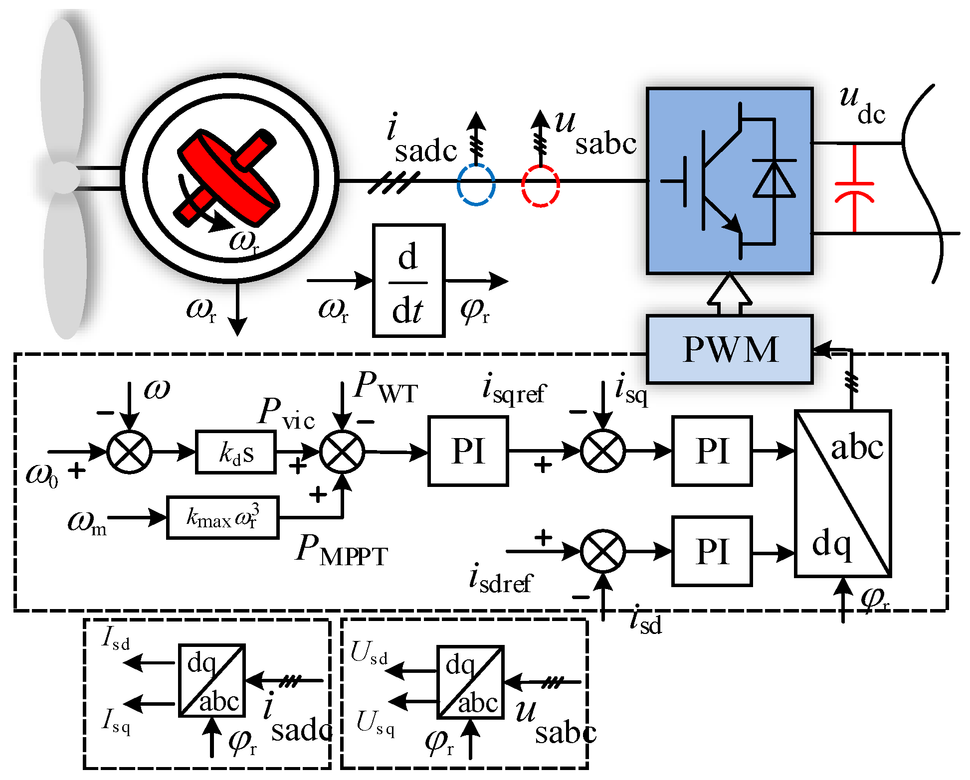
2.2. Circuit Topology and Control Strategy of Wind Turbine Side Converter

The circuit topology and control strategy of the wind turbine side converter of the DPMSG-based WPS are shown in Figure 2. PWT is the output power of the wind turbine, Pvic is the virtual inertia power command and PMPPT is the MPPT power command.
According to Figure 2 and Park’s transformation, the mathematical model of the wind turbine side converter in the dq frame is
L sd d i sd d t = e sd R s i sd + ω r L sq i sq u sd L sq d i sq d t = e sq R s i sq ω r L sd i sd u sq
where ud and uq are the terminal voltage of the wind turbine side converter in the dq frame.
The main goal of power control is to achieve the maximum utilization of wind energy. In order to effectively utilize the kinetic energy on the rotor for the auxiliary support of the microgrid, the control method requires virtual inertia control. This method will affect the rotor speed during this transient to ensure a fast response for the angular frequency. The virtual inertia power command can be expressed as
P vic = k d s Δ ω
where kd is the virtual inertia control coefficient.
The output power of MPPT control can be written as
P MPPT = k max ω r 3
where kmax is the coefficient maximizing captured wind energy.
From Figure 2, the power control command of the wind turbine side converter is
P WTref = P MPPT + P vic
It can be seen from (8) that when the power control is added with virtual inertia control, the essence is to couple the angular frequency with the wind turbine, so that the kinetic energy of the wind turbine can be used to participate in the adjustment process of the angular frequency. For the case of no disturbance in microgrids, the wind turbine operates at the maximum power point.

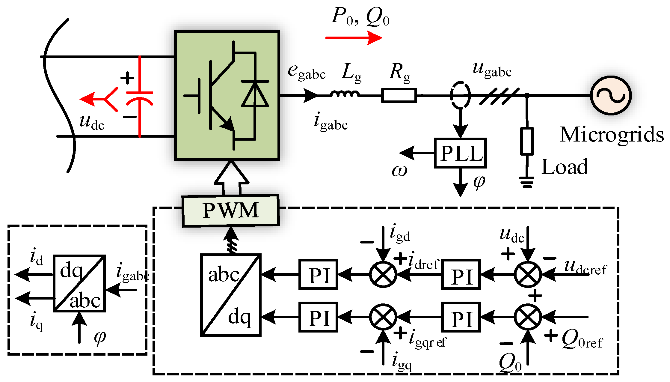
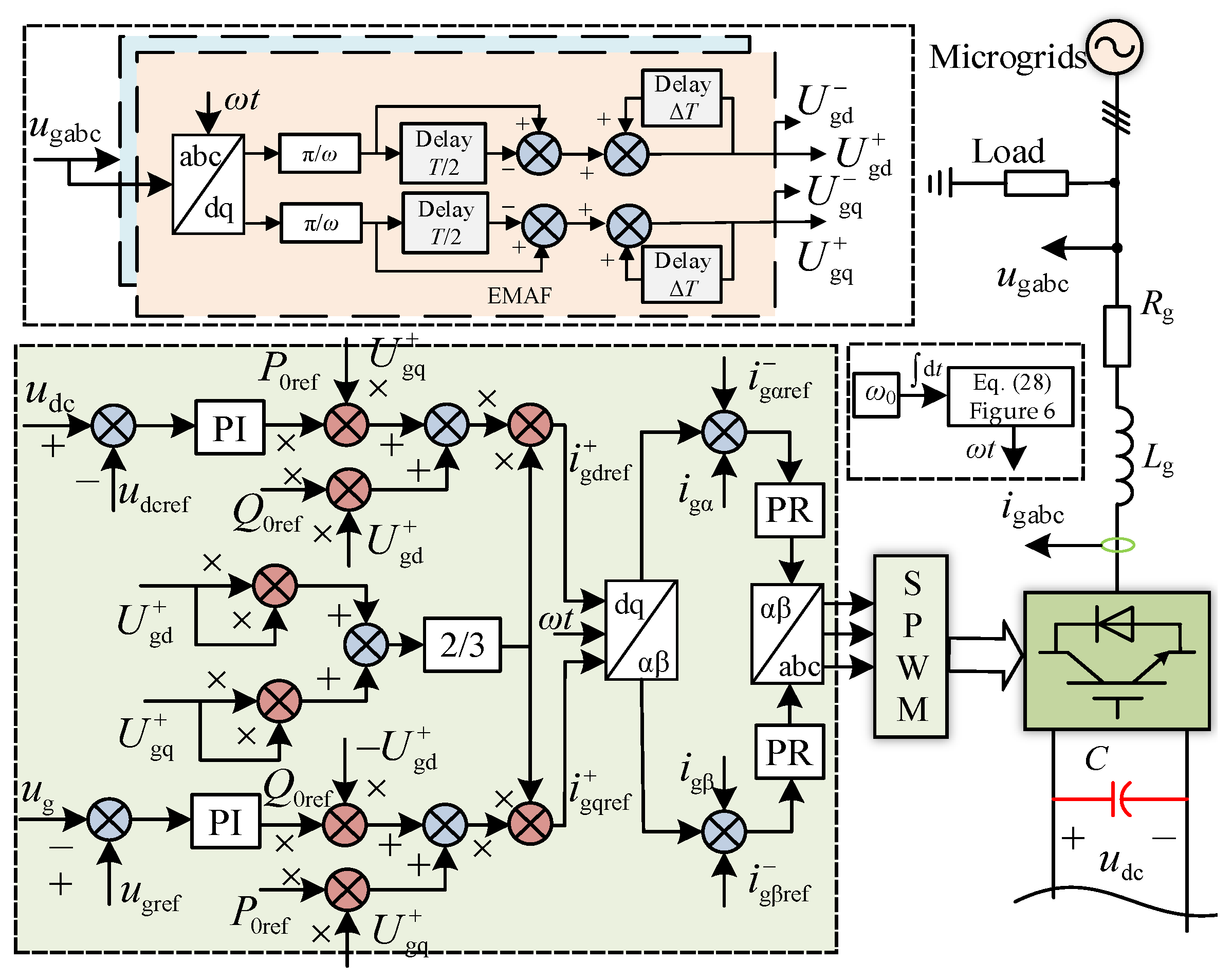
2.3. Circuit Topology and Control Strategy of Grid Side Converter

Figure 3 shows the circuit topology and control strategy of the grid-side converter of the DPMSG-based WPS. The stable control of the capacitor voltage is realized by the grid side converter.
From Figure 3 and Park’s transformation, the mathematical model of the converter is
L gd d i gd d t = U gd i gd R g + ω L g i gq e gd L gq d i gq d t = U gq i gq R g ω L g i gd e gq
where egd and egq are the output voltage of the grid side converter, Ugd and Ugq are the microgrid voltage in the dq frame.
The purpose of the capacitor voltage control is to maintain the stability of DC voltage, so as to ensure that the DPMSG-based WPS can effectively realize the connection with the microgrid. According to Figure 3, the current command of the capacitor voltage control is
i gdref = k p + k i s u dcref u dc
where kp and ki are the proportional and integral coefficients of the capacitor voltage control, udcref is the capacitor voltage command.

3. Synchronous Information Detection Algorithm in Microgrid

Microgrids often suffer from unbalanced three-phase loads, the single-phase-to-ground fault and the two-phase short-circuit, resulting in unbalanced conditions, which lead to the introduction of low-frequency harmonics into the control strategy.
The grid-connected voltage of the DPMSG-based WPS in the unbalanced condition can be expressed as
u ˜ g = u ˜ a ( t ) u ˜ b ( t ) u ˜ c ( t ) = u a + ( t ) + u a ( t ) u b + ( t ) + u b ( t ) u c + ( t ) + u c ( t )
From (11), the positive and negative sequence components of the grid-connected voltage is given by
u a + ( t ) = U m + sin ( ω t + α ) u b + ( t ) = U m + sin ( ω t + α 2 π 3 ) u c + ( t ) = U m + sin ( ω t + α + 2 π 3 )
u a ( t ) = U m sin ( ω t + β ) u b ( t ) = U m sin ( ω t + β + 2 π 3 ) u c ( t ) = U m sin ( ω t + β 2 π 3 )
where α and β are the initial phases of the positive and negative sequence components, Um+ and Um are the amplitudes of the positive and negative sequence components.
(11) is brought into the transformation matrix, which can be obtained as
U ˜ gd U ˜ gq = T a b c / d q ( ω t ) u ˜ g = 2 3 sin ω t   sin ( ω t 2 π 3 )   sin ( ω t + 2 π 3 ) cos ω t   cos ( ω t 2 π 3 )   cos ( ω t + 2 π 3 ) u ˜ a ( t ) u ˜ b ( t ) u ˜ c ( t )
Therefore, (14) can be rewritten as
U ˜ gd U ˜ gq = U m + cos α U m cos ( 2 ω t + β ) U m + sin α + U m sin ( 2 ω t + β )
When the microgrid voltage is asymmetrical, its components still contain negative sequence components in the dq frame. Therefore, the control strategy of DPMSG-based WPS cannot effectively support the microgrid.

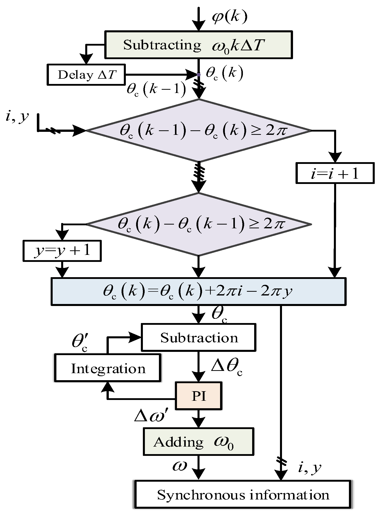
3.1. Detection Principle

The moving average filter algorithm is an effective algorithm for suppressing periodic harmonics [17], which can be written as
f ¯ ( t ) = 1 L t L t f ( x ) d x
where L is the sliding period.
The dynamic response time of this algorithm is proportional to its sliding period. With the increase of sliding period, the dynamic response time of moving average filter algorithm is longer. The transfer function of this algorithm is
G MAF ( s ) = f ¯ ( s ) f ( s ) = 1 e L s L s
According to the amplitude–frequency characteristic of (17), when ω is 2πn/L, the gain of this algorithm is zero. For other values of ω, the algorithm gain is less than 1, and decreases rapidly as ω increases. The moving average filter algorithm is similar to the low-pass filter algorithm (see Figure 4), which can filter out harmonics of specific frequencies.
In order to further analyze the influence of the moving average filter algorithm that filters out the nth harmonic on the mth harmonic, the specific research is as follows. The nth harmonic can be expressed as
f n ( t ) = U m n sin n ω t + θ n
where θmn and Umn are the initial phase and amplitude of the nth harmonic, respectively.
In the transient process of the moving average filter algorithm, it is assumed that the time t is less than the sliding period L. The mth harmonic can be described as
f ¯ m ( t ) = 1 L t L t f m ( x ) d x = 1 L t L 0 f m ( x ) d x + 1 L 0 t f m ( x ) d x = n U m m 2 m π cos m ω t + θ m cos θ m = A m U m m sin m ω t 2 + θ m sin m ω t 2
where Am is the transient amplitude coefficient.
When the algorithm reaches a steady state, the nth harmonic is completely filtered out. The mth harmonic can be described as
f ¯ m ( t ) = 1 L t L t f m ( x ) d x = 1 L t L t U m m sin m ω x + θ m d x = U m m 2 π cos m ω t + θ m cos m ω t + θ m 2 m π n = B m U m m cos m ω t + θ m arctan sin 2 m π n 1 cos 2 m π n
where Bm is the steady-state amplitude coefficient.
The steady-state amplitude coefficient is given by
B m = 2 2 π 1 cos 2 m π n
From (19) and (20), the attenuation capability of the moving average filter algorithm for the transient and steady state of the harmonic amplitude is shown in Figure 5. With the decrease of n, this algorithm has a stronger ability to attenuate the transient harmonics. In the transient process, this algorithm can usually attenuate the amplitude of the harmonics by 60%. When the steady state is reached, the moving average filter algorithm has a good ability to suppress all harmonics.
According to (16), the moving average filter algorithm can be discretized as
f ¯ ( k ) = 1 L j = k L + 1 k f ( j )
In order to filter out multiple harmonics at the same time, an enhanced moving average filter algorithm is used in this paper, which has better flexibility in design. The enhanced moving average filter algorithm can be obtained as
f ¯ ( k ) = 1 N L j = k N L + 1 k f ( j ) = 1 N l = 1 N 1 L j = k l L + 1 k ( l 1 ) L f ( j ) = 0
where N is the magnification of the sliding period.
Therefore, by designing an appropriate sliding period, the enhanced moving average filter algorithm can be used to suppress multiple harmonics. In addition, this algorithm averages high-frequency random noise.

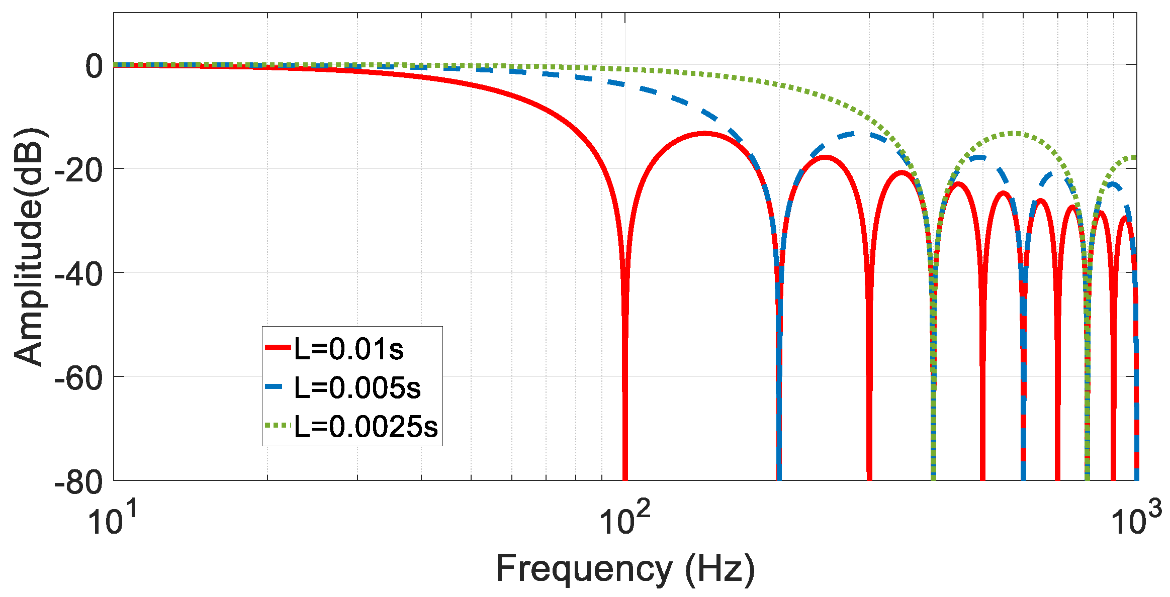
3.2. Fast Detection Algorithm

After the enhanced moving average filter algorithm, the positive sequence component of the voltage in (15) can be expressed as
U gd + U gd + = U m + cos α U m + sin α
The transformation matrix of negative sequence is
T a b c / d q ( ω t ) = 2 3 sin ω t   sin ( ω t + 2 π 3 )   sin ( ω t 2 π 3 ) cos ω t   cos ( ω t + 2 π 3 )   cos ( ω t 2 π 3 )
According to (25) and the enhanced moving average filter algorithm, the negative sequence component can be rewritten as
U gd U gd = U m cos β U m sin β
The initial phase of grid-connected voltage in (24) is
α = arctan U gq + U gd +
This initial phase in (27) is not the initial phase (α ∈ [0, 2π)) of the actual grid-connected voltage, so the compensation phase Zx is introduced in this paper. Therefore, the synchronous phase of the grid-connected voltage of the DPMSG-based WPS can be described as
φ = ω t + α = ω 0 t + arctan U gq + U gd + + Z x
where ω0 is the constant angular frequency and Zx is the compensation phase.
The compensation phase is given by
Z x = 0 U gd + 0 , U gq + 0   π U gd + < 0 2 π U gd + 0 , U gq + < 0
Combining the grid-connected voltage shown in (11) with (14), (23) and (28), the synchronous phase of the grid-connected voltage can be quickly and accurately detected.
In order to further obtain the real-time angular frequency, the synchronous phase of the positive sequence is decomposed into the ideal angular frequency ω0t and the changing phase θc. Therefore, when the microgrid reaches a steady state, the difference angular frequency Δω between the angular frequency ω and the constant angular frequency ω0 also remains stable, which can be expressed as
θ c = Δ ω d t + α
The initial phase α is unknown, so (30) cannot be directly used to calculate the changing phase θc. However, the change amount of the changing phase in a steady state is also in a linear relationship with the difference angular frequency Δω. Therefore, the change amount of the changing phase can be obtained indirectly by the closed-loop control, namely
θ c = Δ ω d t
According to (31), the real-time angular frequency of the microgrid is
ω = ω 0 + Δ ω = ω 0 + K p Δ θ c + K i Δ θ c d t
where Kp and Ki are the proportional and integral coefficients of the angular frequency control.
The algorithm changes the changing phase θc into a continuous phase, and then the noise-free angular frequency can be obtained by the closed-loop control. The flow chart of frequency detection is shown in Figure 6. Therefore, the real-time synchronous information of the microgrid can be calculated through (23), (28) and Figure 6.

4. Disturbance-Suppression Method for Microgrids

Due to the isolation between the DPMSG and the microgrids by the converters, this WPS has certain advantages in assisting the operation of the microgrid compared with the doubly fed induction generator-based WPS. The wind turbine side converter is not directly connected to the microgrid, so the microgrid has little influence on it. However, the grid side converter directly connected to the microgrid is affected by microgrid failures.
From Figure 1, the instantaneous power equation on the grid side can be described as
S = P + j Q = e j ω t U gdq + + e j ω t U gdq e j ω t i gdq + + e j ω t i gdq
According to (33), the instantaneous power of the DPMSG-based WPS is
P = P 0 + P 1 sin ( 2 ω t ) + P 2 cos ( 2 ω t ) Q = Q 0 + Q 1 sin ( 2 ω t ) + Q 2 cos ( 2 ω t )
where P0 and Q0 are the constant components of active and reactive power, P1 and Q1 are the amplitudes of active and reactive sinusoidal components, P2 and Q2 are the amplitudes of active and reactive cosine components, respectively.
It can be seen from (34) that in unbalanced conditions, the active and reactive output power by the DPMSG-based WPS have not only constant power components, but also double frequency power components. From (34), the constant and double frequency power components can be written as
P 0 P 1 P 2 Q 0 Q 1 Q 2 = 3 2 U gd + U gq + U gd U gq U gq U gd U gq + U gd + U gd U gq U gd + U gq + U gq + U gd U gq U gd + U gq U gd U gq U gd + U gq + U gd U gq + U gd + i gd + i gq + i gd i gq
In order to suppress the power fluctuations and the negative sequence current, the commands of the constant and double frequency power components can be expressed as
P 0 = P 0 ref Q 0 = Q 0 ref P 1 = P 2 = 0 Q 1 = Q 2 = 0
where the subscript ref is the reference value of the physical quantity.
By substituting (36) into (35), the sequence current command in the current control loop can be obtained as
P 0 ref Q 0 ref = 3 2 U gd + U gq + U gq + U gd + U gd U gq U gq U gd i gdref + i gqref + i gdref i gqref
For the sequence current problem in the microgrid, the negative sequence current command of the DPMSG-based WPS is
i gdref = i gqref = 0
Substituting (38) into (37), the positive sequence current command can be described as
P 0 ref Q 0 ref = 3 2 U gd + U gq + U gq + U gd + i gdref + i gqref +
Therefore, (39) can be rewritten as
i gdref + i gqref + = 2 3 U gd + 2 + U gq + 2 U gd + U gq + U gq + U gd + P 0 ref Q 0 ref
According to (40), the positive sequence current command of the DPMSG-based WPS can be obtained when the power fluctuation occurs in the microgrid. In order to improve the utilization efficiency of the WPS, the reactive power command is usually zero. The proposed method is shown in Figure 7.
The voltage and current of this method are calculated and controlled, which eliminates the complex dynamic adjustment process. Therefore, this method can significantly improve the grid-connected current control speed of the DPMSG-based WPS, suppress the current overload degree, and rapidly improve the power quality of the microgrid.

5. Verification of Disturbance-Suppression Method

This paper uses the simulation to verify the correctness of the compensation control method. The circuit topology and control method of the DPMSG-based WPS are shown in Figure 1 and Figure 7.

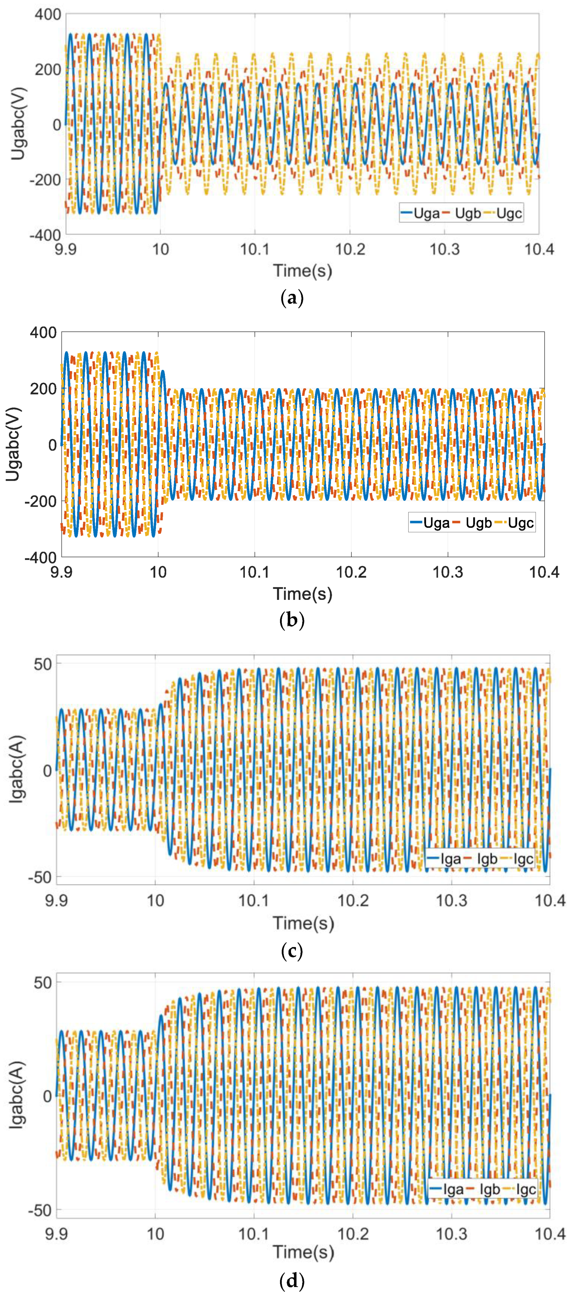
5.1. Simulation Verification

When the microgrid voltage is suddenly reduced and unbalanced, Figure 8 shows the suppression process of the DPMSG-based WPS using the DDSRF-SPLL algorithm and the proposed method. The unbalanced voltage of the microgrid leads to the unbalance of the output current of the DPMSG-based WPS, which makes the current amplitude significantly increase. After being disturbed, the microgrid changes from three-phase balance to three-phase unbalance, and the voltage amplitude decreases (see Figure 8a). The positive sequence voltages obtained by the proposed method are shown in Figure 8b. The current suppression process of the WPS with the DDSRF-SPLL algorithm and the proposed method are shown in Figure 8c,d. Figure 8e illustrates the comparison results of the output current value of the DPMSG-based WPS by this method and the DDSPF algorithm. The output current based on the DDSRF-SPLL algorithm does not contain the negative sequence component after the dynamic response time in Figure 8d. However, this dynamic process is too lengthy to achieve the goal of quickly supporting the microgrid. The suppression time of the DPMSG-based WPS using the two methods is 0.06 s and 0.08 s, respectively. The proposed method has fast response speed and small transient current fluctuation, so that the output current reaches the steady-state value faster.
Figure 9 shows the suppression process of the DPMSG-based WPS with the DDSRF-SPLL algorithm and the proposed method in the case of unbalance and phase increase. After the unbalanced disturbance, the phase of the microgrid voltage increases suddenly, as shown in Figure 9a.
According to Figure 9c,d, the DPMSG-based WPS using the proposed method and the DDSRF-SPLL algorithm can eliminate the unbalance problem and achieve the goal of supporting the microgrid. The response times of the DPMSG-based WPS with the proposed method and DDSRF algorithm to suppress the disturbance are 0.08 s and 0.11 s (see Figure 9e). The dynamic response time of this method is 27.3% faster than that of the DDSRF-SPLL algorithm. Under this working condition, the DPMSG-based WPS with this method can still maintain excellent current control capability.
When the fundamental frequency of the microgrid changes suddenly and the three-phase voltage is unbalanced, the suppression process of the DDSRF-SPLL algorithm and this method is shown in Figure 10. The suppression effect of the proposed method in the wind power system is shown in Figure 10c,e. In Figure 10d,e, the DPMSG-based WPS with the DDSRF-SPLL algorithm can suppress unbalanced conditions to realize compensation current, and its dynamic response time is about 0.08 s. Compared with the DDSRF-SPLL algorithm, the DPMSG-based WPS using the proposed method can compensate the electric energy required by the microgrid faster, and effectively solve the problem of transient unbalance. In Figure 8, Figure 9 and Figure 10, the control ability of the DPMSG-based WPS with the proposed method is significantly improved under complex conditions.

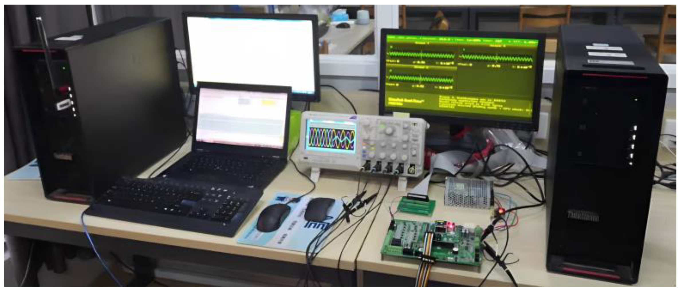
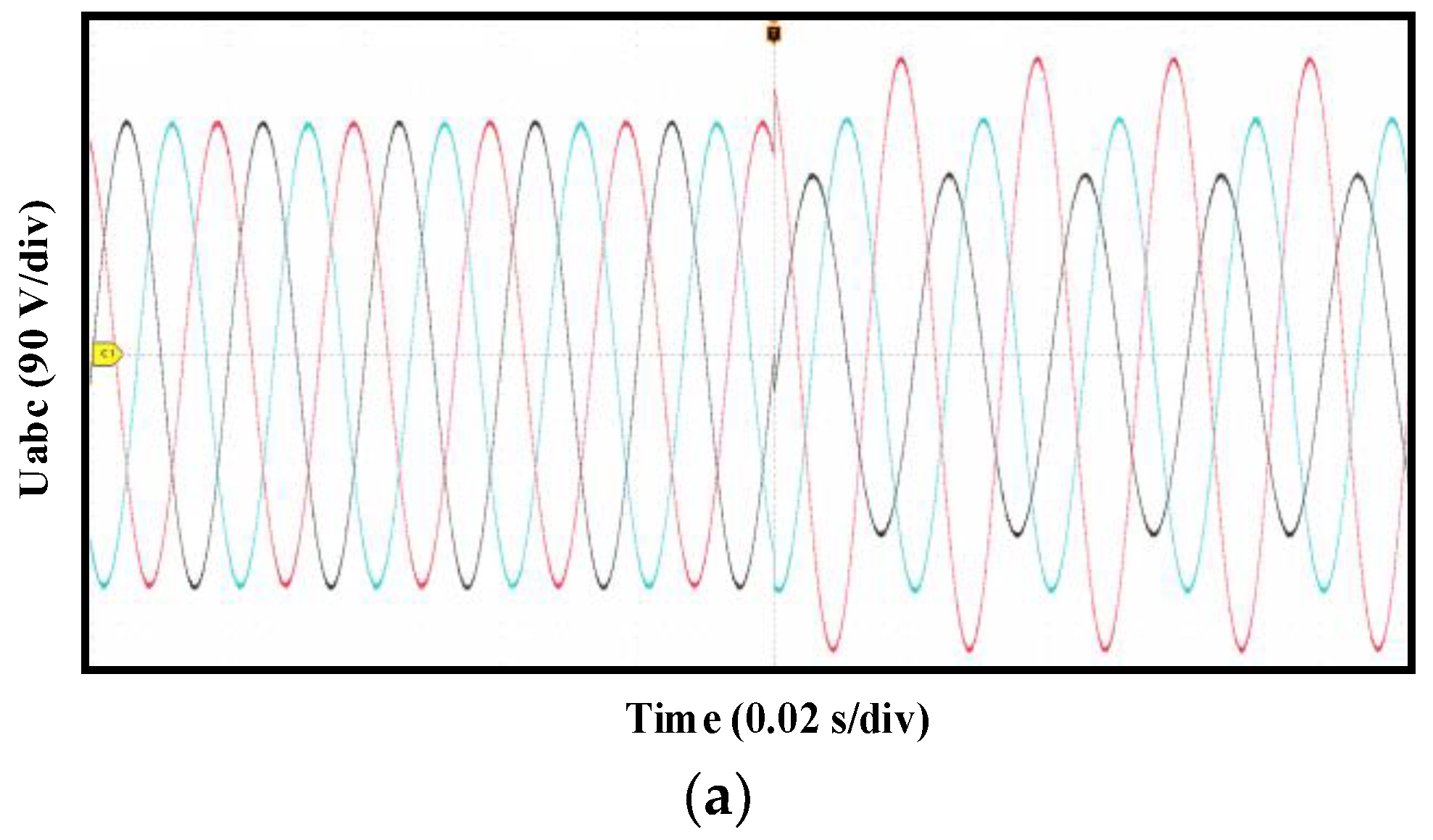
5.2. RT-LAB Verification

In order to verify the correctness and effectiveness of the method proposed in this paper, the RT-LAB platform is used. The hardware setup of the RT-LAB platform is shown in Figure 11.
When the microgrid voltage is severely unbalanced, the suppression process of the method proposed in this paper is shown in Figure 12. The DPMSG-based WPS with the proposed method has the characteristics of fast response speed and small amplitude fluctuation range, which can effectively solve the transient unbalance problem.

6. Conclusions

To solve the power quality problem of the microgrid, this paper proposes a disturbance-suppression method based on the adaptive enhanced moving average filter algorithm for the DPMSG-based WPS. By reducing the complex dynamic adjustment process in the traditional control methods, the proposed method significantly improves the current control speed and enhances the support capability of the microgrid. The response time of this method is less than 0.08 s in complex environments. Compared with the DDSRF-SPLL algorithm, the response time of the proposed method is reduced by 27.3%.
The proposed method can capture the angular frequency by the changing phase, making it adaptable to a wider range of fundamental frequency fluctuations. This method provides the system with higher sensitivity and adaptability to cope with microgrid changes. In addition, this method does not need to separate the current sequence components, which avoids the complexity of feedforward decoupling control and simplifies the structure of the controller. Therefore, the research conclusion can improve the utilization efficiency of the DPMSG-based WPS. In future studies, the scope of application of this method should be broadened (e.g., multiple harmonics and large power grids).

Author Contributions

X.X. and J.H. wrote the manuscript. L.X. conceived and designed the study. R.G. performed the simulation. All authors have read and agreed to the published version of the manuscript.

Funding

This research received no external funding.

Data Availability Statement

Not applicable.

Conflicts of Interest

The authors declare no conflict of interest.

Abbreviations

DPMSGDirect-driven Permanent Magnet Synchronous Generator
WPSWind Power System
DDSRF-PLLDecoupled Double Synchronous Reference Frame Phase-Locked Loop
MPPTMaximum Power Point Tracking
Nomenclatures
ωReal-time angular frequency of microgrid
ωrWind turbine speed
isabcStator current
udcCapacitor voltage
igabcOutput current of grid-side converter
Lg, RgEquivalent inductance and resistance
PLPower consumed by the load
P, QActive and reactive power of DPMSG-based WPS
SArea of fan blade
ρ, vAir density and wind speed
δ, λPitch angle and tip speed ratio
Cp(δ, λ)Utilization coefficient of wind energy
RImpeller radius of wind turbine
ΨfRotor flux linkage of DPMSG
esd, esqStator terminal voltage in dq frame
RsStator winding resistance
Lsd, LsqInductances of direct and quadrature axis
PWTOutput power of wind turbine
PvicVirtual inertia power command
PMPPTMPPT power command
ud, uqTerminal voltage of wind turbine side converter in dq frame
kdVirtual inertia control coefficient
kmaxCoefficient maximizing captured wind energy
egd, egqOutput voltage of grid side converter
Ugd, UgqMicrogrid voltage in dq frame
udcrefCapacitor voltage command
kp, kiProportional and integral coefficients of capacitor voltage control
α, βInitial phases of positive and negative sequence components
Um+, Um−Amplitudes of positive and negative sequence components
LSliding period
θmn, UmnInitial phase and amplitude of nth harmonic
AmTransient amplitude coefficient
BmSteady-state amplitude coefficient
NMagnification of sliding period
ω0Constant angular frequency
ZxCompensation phase
θcChanging phase
Kp, KiProportional and integral coefficients of angular frequency control
P0, Q0Constant components of active and reactive power
P1, Q1Amplitudes of active and reactive sinusoidal components
P2, Q2Amplitudes of active and reactive cosine components

References

  1. Maihemuti, S.; Wang, W.; Wu, J.; Wang, H.; Muhedaner, M.; Zhu, Q. New Energy Power System Dynamic Security and Stability Region Calculation Based on AVURPSO-RLS Hybrid Algorithm. Processes 2023, 11, 1269. [Google Scholar] [CrossRef]
  2. Kaur, P.; Chaturvedi, K.T.; Kolhe, M.L. Economic Dispatch of Combined Heat and Power Plant Units within Energy Network Integrated with Wind Power Plant. Processes 2023, 11, 1232. [Google Scholar] [CrossRef]
  3. Zhang, S.; Zhang, K.; Zhang, G.; Xie, T.; Wen, J.; Feng, C.; Ben, W. The Bi-Level Optimization Model Research for Energy-Intensive Load and Energy Storage System Considering Congested Wind Power Consumption. Processes 2022, 10, 51. [Google Scholar] [CrossRef]
  4. Yan, Z.; Xu, Y. A Hybrid Data-Driven Method for Fast Solution of Security-Constrained Optimal Power Flow. IEEE Trans. Power Syst. 2022, 37, 4365–4374. [Google Scholar] [CrossRef]
  5. Loulijat, A.; Chojaa, H.; El Marghichi, M.; Ettalabi, N.; Hilali, A.; Mouradi, A.; Abdelaziz, A.Y.; Elbarbary, Z.M.S.; Mossa, M.A. Enhancement of LVRT Ability of DFIG Wind Turbine by an Improved Protection Scheme with a Modified Advanced Nonlinear Control Loop. Processes 2023, 11, 1417. [Google Scholar] [CrossRef]
  6. Zhang, D.; Wu, Y.; Xiong, L.; Zhao, C. Analysis of Inertia Characteristics of Direct-Drive Permanent-Magnet Synchronous Generator in Micro-Grid. Energies 2019, 12, 3141. [Google Scholar] [CrossRef] [Green Version]
  7. Coban, H.H.; Rehman, A.; Mousa, M. Load Frequency Control of Microgrid System by Battery and Pumped-Hydro Energy Storage. Water 2022, 14, 1818. [Google Scholar] [CrossRef]
  8. Binbing, W.; Yizhi, T.; Yuxi, C.; Abuduwayiti, X.; Xiong, L. Virtual Frequency Construction-Based Vector Current Control for Grid-Tied Inverter under Imbalanced Voltage. IEEE Access 2020, 8, 199654–199663. [Google Scholar] [CrossRef]
  9. Guediri, A.; Hettiri, M.; Guediri, A. Modeling of a Wind Power System Using the Genetic Algorithm Based on a Doubly Fed Induction Generator for the Supply of Power to the Electrical Grid. Processes 2023, 11, 952. [Google Scholar] [CrossRef]
  10. Liu, X.; Wu, B.; Xiu, L. A Fast Positive-Sequence Component Extraction Method with Multiple Disturbances in Unbalanced Conditions. IEEE Trans. Power Electron. 2022, 37, 8820–8824. [Google Scholar] [CrossRef]
  11. Chao, W.; Deng, C.; Huang, J.; Dai, L.; Min, Y.; Cheng, Y.; Wang, Y.; Liao, J. A Sub-Synchronous Oscillation Suppression Strategy Based on Active Disturbance Rejection Control for Renewable Energy Integration System via MMC-HVDC. Electronics 2023, 12, 2885. [Google Scholar] [CrossRef]
  12. Jiang, P.; Zhang, T.; Geng, J.; Wang, P.; Fu, L. An MPPT Strategy for Wind Turbines Combining Feedback Linearization and Model Predictive Control. Energies 2023, 16, 4244. [Google Scholar] [CrossRef]
  13. Chen, J.; Duan, W.; Yang, X.; Zhang, L.; Shan, Y.; Yang, B.; Shu, H.; An, N.; Yu, T. Overall Adaptive Controller Design of PMSG under Whole Wind Speed Range: A Perturbation Compensation Based Approach. Processes 2019, 7, 732. [Google Scholar] [CrossRef] [Green Version]
  14. Mayilsamy, G.; Palanimuthu, K.; Venkateswaran, R.; Antonysamy, R.P.; Lee, S.R.; Song, D.; Joo, Y.H. A Review of State Estimation Techniques for Grid-Connected PMSG-Based Wind Turbine Systems. Energies 2023, 16, 634. [Google Scholar] [CrossRef]
  15. Xiong, L.; Liu, X.; Zhao, C.; Zhuo, F. A Fast and Robust Real-Time Detection Algorithm of Decaying DC Transient and Harmonic Components in Three-Phase Systems. IEEE Trans. Power Electron. 2020, 35, 3332–3336. [Google Scholar] [CrossRef]
  16. Xiu, L.; He, J.; Li, M. Fast and Stable Detection Scheme of Point of Common Coupling Voltage for Renewable Energy Systems Tied to Distortion Grids. IEEE Trans. Ind. Inform. 2023, 19, 7876–7884. [Google Scholar] [CrossRef]
  17. Xiong, L.; Zhuo, F.; Wang, F.; Liu, X.; Zhu, M.; Yi, H. A Quantitative Evaluation and Comparison of Harmonic Elimination Algorithms Based on Moving Average Filter and Delayed Signal Cancellation in Phase Synchronization Applications. J. Power Electron. 2016, 16, 717–730. [Google Scholar] [CrossRef] [Green Version]
  18. Ademi, S.; Jovanovic, M. High-Efficiency Control of Brushless Doubly-Fed Machines for Wind Turbines and Pump Drives. Energy Convers. Manag. 2014, 81, 120–132. [Google Scholar] [CrossRef]
  19. Bergna, G.; Berne, E.; Egrot, P.; Lefranc, P.; Arzande, A.; Vannier, J.-C.; Molinas, M. An Energy-Based Controller for HVDC Modular Multilevel Converter in Decoupled Double Synchronous Reference Frame for Voltage Oscillation Reduction. IEEE Trans. Ind. Electron. 2013, 60, 2360–2371. [Google Scholar] [CrossRef]
  20. Xiu, L.; Du, Z.; Wu, B.; Li, G.; Wang, D.; Song, H. A Novel Adaptive Frequency Extraction Method for Fast and Accurate Connection between Inverters and Microgrids. Energy 2021, 221, 119795. [Google Scholar] [CrossRef]
  21. Svensson, J. Synchronization Methods for Grid-Connected Voltage Source Converter. Gener. Transm. Distrib. IEE Proc. 2001, 148, 229–235. [Google Scholar] [CrossRef] [Green Version]
  22. Xiong, L.; Zhuo, F.; Wang, F.; Liu, X.; Zhu, M. A Fast Orthogonal Signal-Generation Algorithm Characterized by Noise Immunity and High Accuracy for Single-Phase Grid. IEEE Trans. Power Electron. 2016, 31, 1847–1851. [Google Scholar] [CrossRef]
  23. Ahmed, S.; Gouichiche, A.; Verma, A.; Su, C.-L.; Zakaria, C.; Messlem, Y.; Berkouk, E.M. Open Loop Synchronization Techniques Benchmarking for Distributed Energy Sources Connection. IEEE Access 2022, 10, 63554–63566. [Google Scholar] [CrossRef]
  24. Xiu, L.; Du, Z.; Li, M.; Du, L.; Hao, J.; Kang, Z. A Practical and Fast Sequence Components Detection Scheme for Three-Phase Unbalanced Grid Voltage. Int. J. Electr. Power Energy Syst. 2021, 125, 106385. [Google Scholar] [CrossRef]
  25. Alassaf, A.; Alsaleh, I.; Alateeq, A.; Alafnan, H. Grid-Following Inverter-Based Resource: Numerical State–Space Modeling. Sustainability 2023, 15, 8400. [Google Scholar] [CrossRef]
  26. Guerrero-Bermúdez, O.D.; Martinez, S.; Molina, E.; Candelo-Becerra, J.E. Comparison of Phase-Locked Loops Used for Frequency Measurements in a Low-Inertia Power Grid with Wind Generation. Electronics 2022, 11, 3226. [Google Scholar] [CrossRef]
  27. Sabo, A.; Kolapo, B.Y.; Odoh, T.E.; Dyari, M.; Abdul Wahab, N.I.; Veerasamy, V. Solar, Wind and Their Hybridization Integration for Multi-Machine Power System Oscillation Controllers Optimization: A Review. Energies 2023, 16, 24. [Google Scholar] [CrossRef]
  28. Sun, D.-Y.; Qian, Z.-J.; Shen, W.-Q.; Zhou, K.; Jin, N.-Z.; Chen, Q.-G. Mechanism Analysis of Multiple Disturbance Factors and Study of Suppression Strategies of DFIG Grid-Side Converters Caused by Sub-Synchronous Oscillation. Electronics 2023, 12, 2293. [Google Scholar] [CrossRef]
  29. Bany Issa, M.A.; Al Muala, Z.A.; Bello Bugallo, P.M. Grid-Connected Renewable Energy Sources: A New Approach for Phase-Locked Loop with DC-Offset Removal. Sustainability 2023, 15, 9550. [Google Scholar] [CrossRef]
  30. Zhou, L.; Han, W.; Qi, J.; Zhou, Z. Adaptive PI + VPI Harmonic Current Compensation Strategy under Weak Grid Conditions. Appl. Sci. 2023, 13, 5983. [Google Scholar] [CrossRef]
  31. Mishra, M.K.; Lal, V.N. An Enhanced Control Strategy to Mitigate Grid Current Harmonics and Power Ripples of Grid-Tied PV System without PLL under Distorted Grid Voltages. IEEE J. Emerg. Sel. Top. Power Electron. 2021, 10, 4587–4602. [Google Scholar] [CrossRef]
  32. Xiong, L.; Wu, B.; Liu, X.; Xiu, L.; Wang, D. PLL-Free Voltage Oriented Control Strategy for Voltage Source Converters Tied to Unbalanced Utility Grids. Front. Energy Res. 2022, 9, 796261. [Google Scholar] [CrossRef]
  33. Lin, F.-J.; Tan, K.-H.; Lai, Y.-K.; Luo, W.-C. Intelligent PV Power System with Unbalanced Current Compensation Using CFNN-AMF. IEEE Trans. Power Electron. 2019, 34, 8588–8598. [Google Scholar] [CrossRef]
  34. Maganti, S.; Padhy, N.P. A Feedback-Based Flexible Compensation Strategy for a Weak-Grid-Tied Current-Controlled Converter under Unbalanced and Harmonic Conditions. IEEE Trans. Ind. Appl. 2022, 58, 7739–7753. [Google Scholar] [CrossRef]
  35. Naidu, T.A.; Arya, S.R.; Maurya, R. Multiobjective Dynamic Voltage Restorer with Modified EPLL Control and Optimized PI-Controller Gains. IEEE Trans. Power Electron. 2019, 34, 2181–2192. [Google Scholar] [CrossRef]
  36. Andrew, E.T.; Ahmed, K.H.; Holliday, D. A New Model Predictive Current Controller for Grid-Connected Converters in Unbalanced Grids. IEEE Trans. Power Electron. 2022, 37, 9175–9186. [Google Scholar] [CrossRef]
Figure 1. Circuit topology of DPMSG-based WPS.
Processes 11 02189 g001
Figure 2. Circuit topology and control strategy of wind turbine side converter.
Processes 11 02189 g002
Figure 3. Circuit topology and control strategy of grid side converter.
Processes 11 02189 g003
Figure 4. Amplitude–frequency characteristic of moving average filter algorithm.
Processes 11 02189 g004
Figure 5. Attenuation capability of moving average filter algorithm for harmonics. (a) Transient amplitude of harmonics. (b) Steady-state amplitude of harmonics.
Processes 11 02189 g005
Figure 6. Flow chart of frequency detection.
Processes 11 02189 g006
Figure 7. Disturbance-suppression method for the DPMSG-based WPS.
Processes 11 02189 g007
Figure 8. Comparison results of amplitude change. (a) Three-phase voltage. (b) Positive sequence voltages of the proposed method. (c) Suppression process of the proposed method. (d) Suppression process of DDSRF algorithm. (e) Output current value.
Processes 11 02189 g008aProcesses 11 02189 g008b
Figure 9. Comparison results of phase change. (a) Three-phase voltage. (b) Positive sequence voltages of the proposed method. (c) Suppression process of the proposed method. (d) Suppression process of DDSRF algorithm. (e) Output current value.
Processes 11 02189 g009aProcesses 11 02189 g009b
Figure 10. Comparison results of frequency change. (a) Three-phase voltage. (b) Positive sequence voltages of the proposed method. (c) Suppression process of the proposed method. (d) Suppression process of DDSRF algorithm. (e) Output current value.
Processes 11 02189 g010aProcesses 11 02189 g010b
Figure 11. RT-LAB platform adopted in this work.
Processes 11 02189 g011
Figure 12. Suppression process of the proposed method in unbalanced environment. (a) Three-phase voltage. (b) Suppression process.
Processes 11 02189 g012aProcesses 11 02189 g012b
Table 1. Comparative table of different state-of-the-art research studies.
ReferenceStudied IssuesGenerating SourcesContribution
[25]Amplitude, phase, frequency and unbalanceGridA PLL state-space model for addressing grid unbalance problems is developed.
[26]Amplitude and phaseWind/GridThe impact of different PLL configurations on the WPS is studied.
[27]Amplitude and phasePV/Wind/GridVarious technical solutions with the renewable energy sources are also reviewed.
[28]Amplitude, phase and frequencyWindr/GridA comprehensive strategy for oscillation suppression is proposed based on the resonance controller.
[24]Amplitude, phase and unbalancePV/Wind/GridA fast detection algorithm for unbalanced voltage is proposed.
[29]Amplitude, phase and frequencyPV/Wind/GridThis algorithm solves the problems of frequency mutation and voltage offset.
[30]Amplitude, phase, frequency and unbalancePV/Wind/GridThis algorithm based on the adaptive lattice notch filters improves the detection accuracy.
Disclaimer/Publisher’s Note: The statements, opinions and data contained in all publications are solely those of the individual author(s) and contributor(s) and not of MDPI and/or the editor(s). MDPI and/or the editor(s) disclaim responsibility for any injury to people or property resulting from any ideas, methods, instructions or products referred to in the content.

