Article

Study on Casing Safety Evaluation in High-Temperature Wells with Annular Pressure Buildup

1
CNPC Engineering Technology R&D Company Limited, Beijing 102206, China
2
College of Petroleum Engineering, China University of Petroleum, Beijing 102249, China
*
Author to whom correspondence should be addressed.
Processes 2023, 11(7), 1915; https://doi.org/10.3390/pr11071915
Submission received: 19 May 2023 / Revised: 20 June 2023 / Accepted: 20 June 2023 / Published: 26 June 2023

Abstract

:
In high-temperature wells, annular pressure buildup (APB) caused by temperature increase is a widespread phenomenon in production, especially in offshore thermal recovery wells. It increases the load on the tubing and casing and consequently threatens the wellbore integrity. Hence, research on casing safety evaluation and APB management has great significance for field production. In this paper, the tubing and casing safety evaluation and APB limit determination methods are presented considering the effect of thermal stress and APB. Based on the case study of an offshore thermal recovery well, an APB-management chart and the recommended optimal range of APB are provided. Finally, an analysis of three commonly used mitigation methods is presented. The effect and the recommended parameters of these mitigation methods are further discussed. The research results show that the thermal stress and APB phenomena affect the stress distribution of the casing and may bring great danger to the wellbore integrity. Maintaining the APB in the safety range is necessary for field production. It is recommended that the annular pressure be kept below the critical value given in this paper. Injecting nitrogen in annulus A and installing rupture disks are both effective methods to improve casing safety. In the case study, the APB decrease percentage is more than 75% when nitrogen is injected in annulus A. However, the nitrogen pressure, the rupture pressure and the installation depth of the rupture disk need to be determined via casing safety evaluation. The effect of optimizing the steel grade and thickness of the tubing and casing is not significant. They can be used as assistance methods when other mitigation methods are adopted.

1. Introduction

With the increase in drilling depth and the exploitation of offshore oil and gas, the problem of high-temperature well production is becoming more and more prominent. As an unconventional fossil resource produced by high-temperature wells, heavy oil is considered to be a significant source of world oil and gas growth [1]. In Bohai Bay, China, 50.4% of total offshore oil reserves are heavy oil [2]. Most of the offshore heavy oil reservoirs are exploited via the thermal recovery method [3] (mostly is steam or thermal fluid injection). In the later process of steam injection, wellbore temperature reaches the maximum, leading to the riskiest situation [4]. The temperature increase of strings and annulus fluid is caused by heat transfer and it may increase the annular pressure, which is known as the annular pressure buildup (APB) phenomenon [5]. The annuli between the casings are defined as “A”, “B” and “C” from the inside out. The wellbore structure is shown in Figure 1. APB is a serious problem in high-temperature well production and has been widespread internationally. It may cause casing failure or destroy wellbore integrity, and further lead to significant safety accidents and economic loss [4,5]. The casing collapsed due to APB in the well Pompano A-31 in the Gulf of Mexico [6]. APB also resulted in a casing failure in the Marlin A-2 well [7,8]. APB in the A annulus can be released through the surface equipment in most onshore and offshore wells. However, the release may not be possible in outer annuli in subsea wells because of the wellhead limits [9]. Therefore, research on casing safety evaluation and APB limit determination has great engineering significance and is favorable for maintaining wellbore integrity and ensuring the efficient development of the heavy oil [10].
Many scholars have researched APB prediction and casing failure. Considering the coupling effect of pressure and volume, a mathematical model for calculating APB was derived by Oudeman et al. [11,12]. Liu et al. [13] developed an APB prediction model that could be used for offshore wells. Yin et al. [14] further optimized the model by taking the variance of the physical parameters into account. Hasan et al. proposed a semi-steady state temperature prediction method of the wellbore and annulus fluid [15]. A higher production rate will cause higher APB [16]. Wang et al. proposed a novel prediction model to predict the APB in an annulus with gas and liquid. They also conducted physical experiments to further analyze the effect of the dissolved gas and cement on APB [17,18]. Xu et al. analyzed the causes of the casing damage that occurred in Du 84. The effect of several prevention measures was also discussed in their work [19]. Liu et al. analyzed the casing fatigue in thermal recovery wells through numerical simulations. Then four fatigue life models were adopted to analyze the casing fatigue life based on a field case [20]. Gao considered the effect of temperature on casing properties and the triaxial thermal stresses in the casing were calculated [21]. Liang analyzed the casing thermal stress and wellhead growth phenomenon. The cement level was further optimized to reduce the casing thermal stress [22]. Ferreira et al. evaluated the application of vacuum insulated tubing (VIT) and its effect on APB. The optimal installation length and position of the VIT are also given in their paper [23].
Scholars have also researched the mitigation of APB [24], including the following:
  • Well structure: make the top of cement (TOC) below the previous casing shoe; full cementing; liner cementing [25];
  • String materials: casing covered with compressible material [26]; optimization of casing size and steel grade [27]; vacuum insulated tubing [23];
  • Equipment: rupture disk [28]; unidirectional pressure control tool;
  • Technological measures: injecting N2 or compressible liquid into annuli [29]; adopting foam spacer.
However, each of the above methods has its limits and application range. Designing appropriate operating parameters for these methods is an important job. Safety and economy must both be considered. The casing safety evaluation and the APB limit determination are prerequisites and essential for the design of mitigation methods. However, there is a lack of research on tubing and casing safety evaluation under high-temperature conditions. APB limit determination and management are also important topics that need to be studied urgently.
In this work, considering the thermal stress, the safety of the casing under APB is evaluated based on APB prediction. Then a method of APB limit determination is proposed through a case study of an actual offshore well and APB-management charts and the recommended range are provided. Furthermore, three commonly used mitigation methods are analyzed and operation parameters are also recommended in this work. It is hoped that this work could provide help for the engineering design of APB management and mitigation.

2. APB-Prediction Model

According to the equation of state, fluid pressure is the function of volume, temperature and mass. Therefore, the relationship of the pressure change, the temperature change and the volume change of the annular fluid is established to achieve the APB value. When the annulus is sealed, the equation is expressed as follows [17,18]:
T i n i T f i n a i s o b d T P i n i P f i n k i s o t d P = ln V f i n V i n i
where
V f i n = V i n i + Δ V f Δ V f = Δ V i s o b + Δ V i s o t Δ V a n n = Δ V f
The isobaric thermal expansion coefficient and isothermal compression coefficient vary with the temperature and pressure of the fluid. Hence, they can be rewritten as:
a i s o b = f P , T k i s o t = g ( P , T )
The function can be fitted with experimental data or calculated with the equation of state [23,28]. In this work, the function is obtained from experimental data fitting [30]. The equations are shown in Equations (4) and (5).
α i s o b = p 11 + p 12 T + p 13 T 2 + p 14 T 3 + p 15 P + p 16 P 2 1 + p 17 T + p 18 P
k isot = p 21 + p 22 T + p 23 T 2 + p 24 P 1 + p 25 T + p 26 P + p 27 P 2
From Equation (2), the volume change of the annular fluid includes two parts. The first part is the volume change caused by isobaric thermal expansion. The second is the volume change caused by isothermal compression. When the annulus is sealed, the volume change of the annular fluid is equal to the annular volume change. The annular volume change can be obtained as follows [29].
(1) Radial displacement of the casing caused by thermal expansion [31]:
u t = ( 1 + 2 μ ) α r Δ T r
(2) Radial displacement of the casing caused by internal and external pressures [31]:
u p = 1 + μ E r o 2 r i 2 r i 2 r o 2 P o P i r + ( 1 2 μ ) P i r i 2 P o r o 2 r
The volume change of the annulus is:
Δ V a n n = π 0 L r o + u t + u p 2 r i + u t + u p 2 r o 2 r i 2 d z
The fluid mostly consists of liquid and gas. The volume change of the liquid can be obtained from Equation (1) and the volume change of the gas can be obtained from the equation of state as follows [32]:
P = R T v ˜ b a c a v ˜ 2 + 2 b v ˜ b 2
where
a = 1 + m 1 T r 0.5 2 a c = 0.457235 R 2 T c 2 / P c m = 0.374640 + 1.54226 ω 0.26992 ω 2 b = 0.077796 R T c / P c
Hence, the annular pressure can be found through the process shown in Figure 2.

3. Tubing and Casing Safety Evaluation

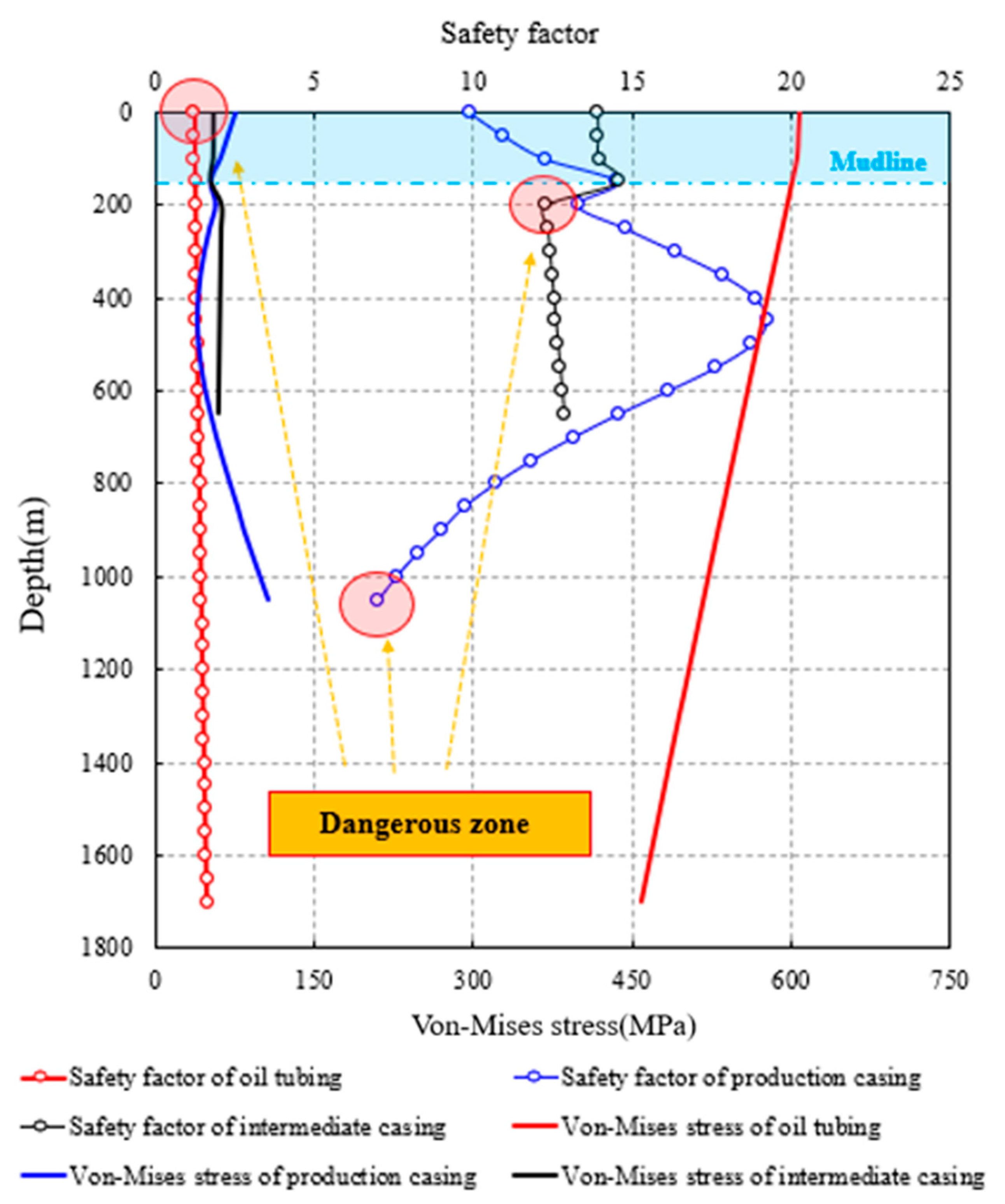
3.1. Tubing and Casing Safety Evaluation

To determine the limit of APB, it is necessary to first conduct a safety evaluation of the tubing and casing. Due to the high temperature and the constraint of the wellhead, the thermal stress caused by temperature has a great effect on the casing stress distribution. Hence, the casing stress consists of the thermal stress and the stress caused by internal and external pressure. The casing stress is shown in Figure 3.
According to the elastic mechanics, the stress caused by pressure and temperature can be obtained as follows [33]:
σ r = P i r i 2 P o r o 2 r o 2 r i 2 + r i 2 r o 2 P o P i r 2 r o 2 r i 2 σ θ = P i r i 2 P o r o 2 r o 2 r i 2 r i 2 r o 2 P o P i r 2 r o 2 r i 2 σ z = F G π r o 2 r i 2 + μ σ θ + σ r
σ θ t = E α Δ T w 2 ( 1 μ ) 1 ln K r ln K K r 2 + 1 K 2 1 σ r t = E α Δ T w 2 ( 1 μ ) ln K r ln K + K r 2 1 K 2 1 σ z t = E α Δ T w 2 ( 1 μ ) 1 2 ln K r ln K 2 K 2 1 a E Δ T r
The pressure on the casing can be calculated with the following equations.
P i = Δ P i + g 0 H ρ i cos θ d z P o = Δ P o + g 0 H ρ o cos θ d z
Hence, the total casing stress can be written as:
σ r = σ r p + σ r T σ θ = σ θ p + σ θ T σ z = σ z p + σ z T
The von Mises criterion is used in this work to conduct the casing stress check and evaluate casing safety [31]. The von Mises stress equation is shown in Equation (14). The safety factor is shown in Equation (15). When the total stress on the casing exceeds the yield strength, casing failure may occur.
σ Mises   = 2 2 σ r σ θ 2 + σ θ σ z 2 + σ z σ r 2 Y p
S = σ Mises   Y p
Once the temperature distribution of the wellbore and the APB in annuli are obtained, the casing stress can be calculated via Equations (10) and (11). Then the safety factor of the casing at different depths can be found with Equation (15).

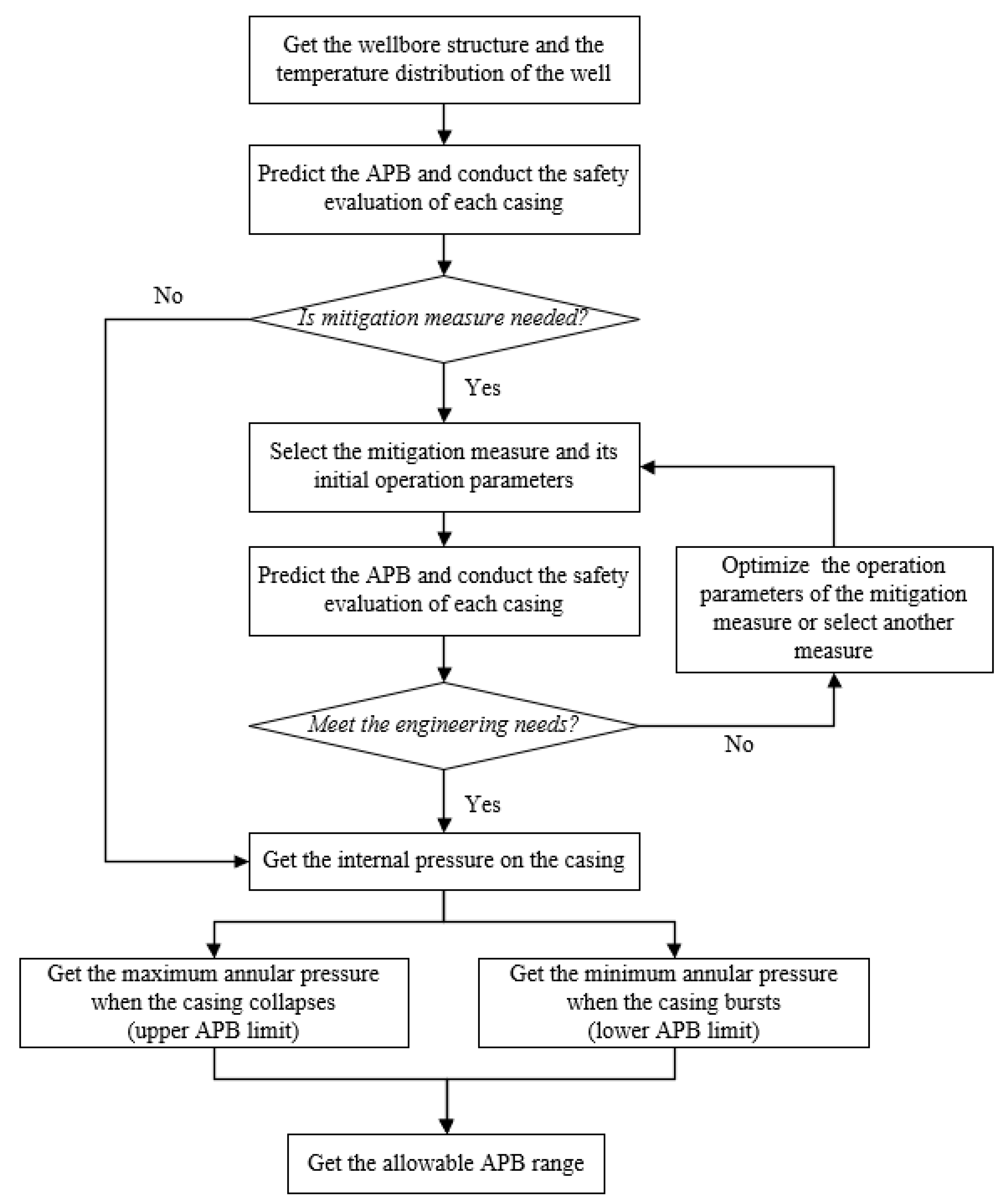
3.2. APB Limit Determination

The APB limit is the maximum or minimum allowable APB that does not cause casing damage. Therefore, the APB limit can be determined by combining the casing safety-evaluation method and the APB-prediction model. The key is to determine the minimum pressure difference when casing collapse or burst occurs. The process of the determination of the APB limit is shown in Figure 4.
Through the process in Figure 4, the APB upper and lower limit values could be determined. Keeping the annular pressure in the allowable range could ensure the safe production of high-temperature wells with APB and avoid unnecessary economical loss.

4. Application and Discussion
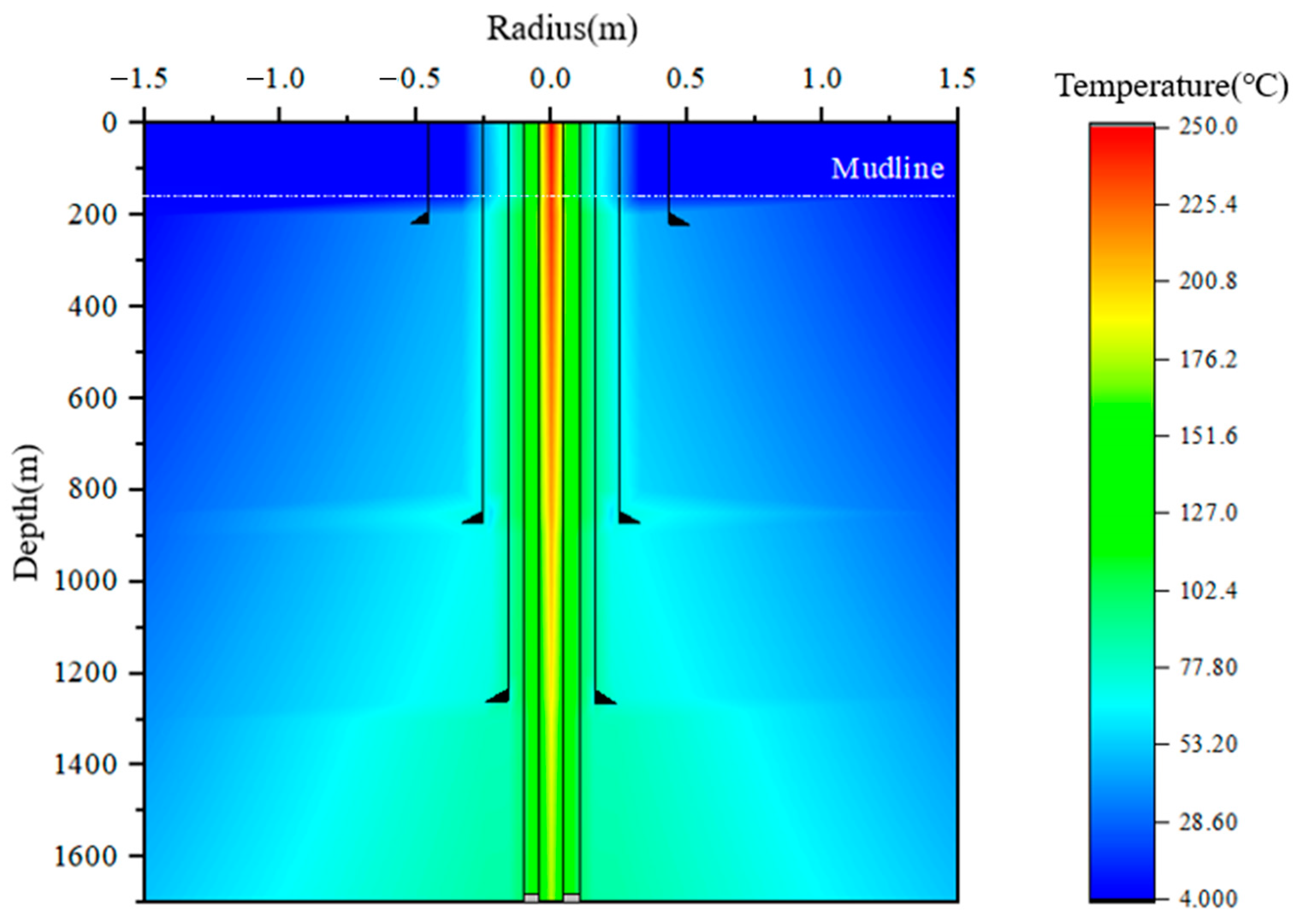
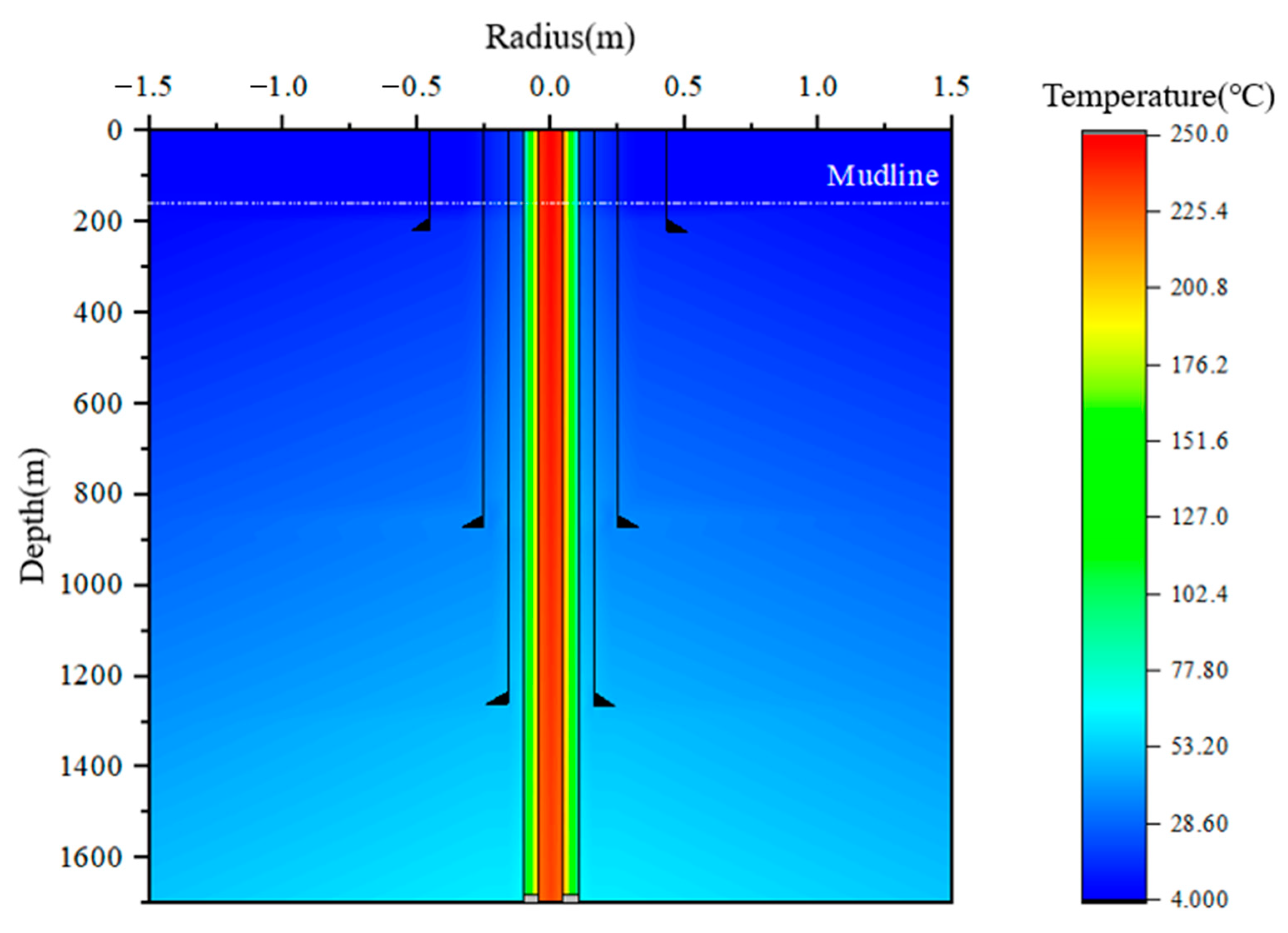
4.1. Case Study

The case study is based on the parameters of a field offshore vertical well. Wellbore structure is demonstrated in Figure 1. The mudline depth is 148 m and the well depth is 1850 m. The depth of the packer is 1712 m. To reduce heat loss, vacuum insulated tubing (VIT) is used. The casing program parameters are shown in Table 1. The input data used for calculation are shown in Table 2.
In this case, the wellbore temperature distribution was calculated with the semi-steady state temperature prediction model [15], which is commonly used in wellbore temperature prediction. The temperature distribution of this well is shown in Figure 5.
From Figure 5, the heat transfers from the tubing to the outside and it increases the temperature around the wellbore. This is the essential cause of the APB problem and the thermal stress of the casing. The temperature of the steam is also decreased by heat dissipation when it arrives at the bottom of the well. In this well, the steam temperature decreases from 250 °C to 176 °C, while 29.6% of the heat is lost. Hence, control of the heat dissipation in the thermal recovery well is of great importance. Using high-quality vacuum insulated tubing (VIT) or heat-insulated spacer fluid can not only ensure the efficiency of heavy oil recovery but also reduce the risk of APB.
The APB in three annuli is calculated under the temperature distribution. The casing safety evaluation is conducted and the APB limit is also determined accordingly. The APB results are shown in Table 3.
The casing safety evaluation results are shown in Figure 6.
Figure 6 presents the casing stress and safety factors. The safety factors of tubing and production casing are less than 1.0, which means damage risk. The dangerous point of the tubing is at the bottom. This is because the external pressure increases with the increasing depth. However, the dangerous point of the production and intermediate casing is around the mudline. This is due to the great temperature difference between the heated fluid and the surrounding environment.
In accordance with the safety-evaluation method of tubing and casing, the APB limits can be obtained as shown in Figure 7.
In Figure 7, the green shaded area is the safety zone; it can be seen that keeping the annular pressure in this range could ensure the safety of the casing and the wellbore integrity. The upper and lower limit value is the maximum and minimum allowable annular pressure. It may bring a great risk of damage to the casing if the annular pressure is in the dangerous zone. Hence, maintaining the pressure in the safety zone is necessary and the pressure beyond the upper limit or below the lower limit value is strictly prohibited in field production.
To provide better guidance for APB management, the recommended optimal range of annular pressure is given in Figure 8 in accordance with the APB limit analysis. The lower limit value is set as 0 MPa, which makes the critical value lower than the upper limit value. This is more appropriate for field pressure management and the casing safety is more fully guaranteed. When the pressure is beyond the critical value, it may bring damage to the casing on one side but this is not inevitable. The more the pressure exceeds the critical value, the greater the probability of casing failure.
It is important to note that the critical value of APB in annulus B is lower compared to other annuli. Hence, the management of APB in annulus B is more important considering that pressure release in annulus B is more difficult.
In the field operation of this well, the annular pressure should be kept below the critical value in Figure 8. If the pressure of an annulus exceeds the critical value in some cases, the adjacent annular pressure should be controlled strictly according to the management chart in Figure 7.

4.2. Analysis of the Mitigation Methods

4.2.1. Nitrogen or Foam Injection

In some thermal recovery wells, nitrogen is injected into annulus A for thermal insulation and to reduce heat loss [34]. In the well in the case study, the fluid in annulus A is fully replaced by nitrogen with 20 MPa. The temperature distribution when the annulus A is filled with nitrogen is shown in Figure 9.
The average temperature increment and APB in each annulus are presented in Table 4.
When annulus A is filled with nitrogen, the temperature of the steam at the bottom increases from 176 °C to 234 °C. This means 78.38% of the heat loss is avoided. The average temperature increment in annulus A increases from 105.12 °C to 111.54 °C, while that in annulus B and C decreases to 16.95 °C and 13.06 °C. The heat insulation property of nitrogen ensures the high temperature of the steam. Meanwhile, the APB in each annulus undergoes a large decrease and the decrease percentages are all more than 75% because of the good compression property of the nitrogen.
The casing safety evaluation results are shown in Figure 10.
In Figure 10, the safety factors of tubing and casing increase significantly with the nitrogen in annulus A. The dangerous point of production casing changes to the bottom and that of tubing changes to the wellhead. This is because the external pressure on the tubing and the thermal stress of the casing decrease. According to the management chart in Figure 7 and Figure 8, the APB in each annulus is all in the safety zone and the wellbore integrity is guaranteed. It is concluded that injecting nitrogen into annulus A is an effective method to improve casing safety.
To maintain tubing and casing safety, the nitrogen injection pressure is optimized. The optimization results are shown in Figure 11.
With the increase in nitrogen pressure, the tubing and casing stress increases and the safety factor decreases. Failure may occur on tubing and production casing when the nitrogen pressure is more than 52 MPa and 65 MPa, respectively. Hence, the nitrogen pressure should be kept below 52 MPa and as low as possible.

4.2.2. Selection of the Rupture Disk

The rupture disk is a device that ruptures under a certain pressure difference. It is often installed on the casing string. When it ruptures, the adjacent annuli are connected and fluid mass exchange occurs. The pressure difference on the casing is eliminated and the external and internal pressure become equal. In this work, the selection of rupture pressure of the rupture disk and its maximum installation depth are both analyzed. The rupture pressure of the disk is as follows:
Casing failure mainly involves collapse and burst. To avoid both accidents, the safe pressure in Equation (16) is the minimum pressure difference when the casing collapses and bursts. The minimum allowable pressure difference of the casing is shown in Figure 12.
P w o r k P r u p P s a f e
To avoid casing failure, the rupture pressure is set at 80% of the minimum allowable pressure difference of the casing. The maximum rupture pressure of the disk for the different casing is shown in Table 5.
In the production of the well in the case study, the maximum work pressure is 20 MPa and the design safety coefficient of the minimum rupture pressure is 1.2. The rupture pressure of the disk should be 24 MPa–53.4 MPa for the production casing and 24 MPa-39.1 MPa for the intermediate casing. For this well, a rupture disk with 27.6 MPa (4000 psi) or 34.5 MPa (5000 psi) rupture pressure is appropriate.
The maximum installation depth of the rupture disk can be calculated as follows:
H r u p = P r u p C s P w o r k | Δ ρ | g
The maximum installation depth of the rupture disk is shown in Figure 13.
With an increase in the density difference between the fluid in adjacent annuli, the maximum installation depth of the rupture disk decreases. When the density of the annular fluid is 1000 kg/m3 and one of the annuli is fully empty, the maximum installation depth is only 363.3 m for 27.6 MPa rupture disk and 1066.3 m for 34.5 MPa rupture disk. Hence, the 34.5 MPa rupture disk is recommended in this well.
To conclude, the rupture disk should be selected according to the casing safety evaluation and Equation (16). It is also necessary to install the rupture disk above the maximum installation depth and as close to the wellhead as possible.

4.2.3. Optimization of the Casing Grade and Thickness

Adopting appropriate casing is also a convenient and economical method to protect wellbore integrity. In this work, a safety evaluation of tubing and casing with different steel grades and thicknesses is conducted.
The steel grade determines the yield strength of the tubing and casing and accordingly affects the wellbore integrity. Thickness affects the stress distribution of the casing and its safety. Based on the well parameters in the case study, the safety evaluation results of the tubing and casing of different steel grades and thicknesses are shown in Figure 14.
As shown in Figure 14a, the casing steel grades with high yield strength have higher safety factors. The safety factors of tubing and casing are all greater than 1 if the grade TP155V is adopted. However, the safety factor of oil tubing is only 1.03, which means a very small margin of safety is left. Hence, just optimizing the grade of tubing and casing is not enough to ensure wellbore safety. It is necessary to adopt other mitigation methods.
From Figure 14b, the safety factor increases with the increase of the thickness. The minimum thickness that could ensure the tubing safety is 12 mm. For production and intermediate casing, it is 13 mm and 8 mm. This is because the pressure on the intermediate casing is less than that on production casing and oil tubing, which means a thinner thickness is enough to bear the load. Meanwhile, with the increase in the thickness, the increase in the safety factor becomes slower. This means the effect of increasing thickness on improving tubing and casing safety decreases gradually. Hence, the thickness should be more than 13 mm if other mitigation methods are not implemented.
To conclude, optimizing the steel grade and thickness of the tubing and casing has a weaker effect compared to other APB-mitigation methods. Selecting a thicker casing with high steel grade could contribute to ensuring the safety of the wellbore. The priority of the selection of these two parameters depends on the economic cost.

5. Conclusions and Suggestions

(1)
Based on the APB-prediction model proposed, the casing safety evaluation and APB limit determination methods of the high-temperature wells are presented in this work. Research shows that the APB phenomena and the thermal stress caused by high temperature affect the stress distribution of the casing and may bring great danger to the wellbore integrity.
(2)
The establishment method of the APB-management chart and the recommended optimal range are given in the case study. Maintaining the annular pressure in the safety zone is necessary in field production. The annular pressure should be kept below the critical value recommended in this work. If the pressure in an annulus exceeds the critical value, the adjacent annular pressure should be controlled strictly according to the APB-management chart.
(3)
Nitrogen injection in annulus A is an effective method to improve casing safety. The heat insulation and compression properties of nitrogen ensure the high temperature of the steam and reduce the APB in each annulus. The APB decrease percentage is more than 75% in the case study. With the increase in the nitrogen pressure, the safety factors of the tubing and casing decrease. The nitrogen pressure should be controlled below the maximum allowable pressure obtained from casing safety evaluation.
(4)
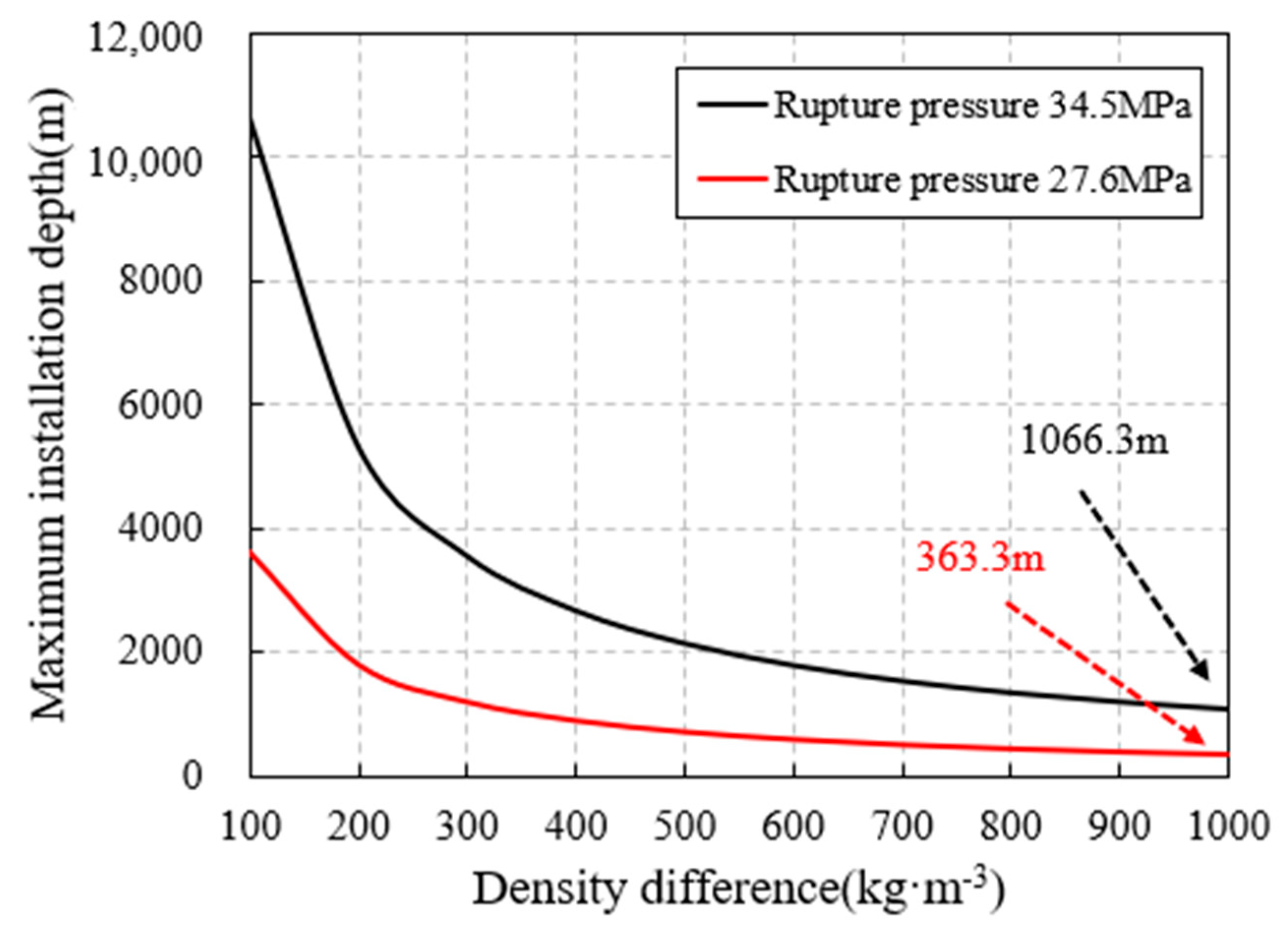
When the rupture disk is installed on the casing, its rupture pressure should be between the maximum operating pressure and the minimum casing safety pressure, and the safety margin is recommended because of the pressure surge. Its maximum installation depth also needs to be determined according to the density of the annular fluid. In the case study, the maximum installation depth of 27.6 MPa rupture disk is only 363.3 m, so the 34.5 MPa rupture disk is recommended.
(5)
The effect of optimizing the steel grade and thickness of the tubing and casing is not significant. They can be used as assistance methods when other mitigation methods are adopted. Selecting a thicker casing with high steel grade could contribute to ensuring the safety of the wellbore. The priority of the selection of these two parameters depends on the economic cost.

Author Contributions

All the authors conceived and designed the study. Conceptualization, H.W.; Writing—original draft, H.W. and M.L.; Supervision, Q.Z. and H.Z.; Funding acquisition, W.H. and Y.L.; Writing—review & editing, P.H. and Y.Z. All authors have read and agreed to the published version of the manuscript.

Funding

This research was funded by CNPC research project grant number [2022ZG06] and the subject grant number [2021DJ4105] under the CNPC research project grant number [2021DJ4100].

Data Availability Statement

Not applicable.

Acknowledgments

This work is supported by CNPC research project “Research on Key Technologies and Equipment for Ultra-Deep Oil and Gas Resource Drilling over 10,000 Meters” (No. 2022ZG06) and the subject “Research on Cementing Seal Integrity technology in Complex Ultra-Deep Wells” (No. 2021DJ4105) under the CNPC research project “Research on optimal and fast drilling technology for deep and ultra-deep Wells” (No. 2021DJ4100).

Conflicts of Interest

The authors declare no conflict of interest.

Nomenclature

T i n i initial annular temperature (K)
T f i n final annular temperature (K)
α i s o b isobaric thermal expansion coefficient of the annular fluid (1/K)
T annular fluid temperature (K)
P i n i initial annular pressure (MPa)
P f i n final annular pressure (MPa)
K i s o t isothermal compressibility of the annular fluid (1/MPa)
P annular fluid pressure (MPa)
V f i n final volume of the annular fluid (m3)
V i n i initial volume of the annular fluid (m3)
V f i n volume change of the annular fluid (m3)
V i s o b volume change of the annular fluid caused by isobaric thermal expansion (m3)
V i s o t volume change of the annular fluid caused by isothermal compression (m3)
V a n n volume change of the annulus (m3)
p 11 fitting coefficient, p 11 = 2.4475 × 10 5
p 12 fitting coefficient, p 12 = 8.3417 × 10 6
p 13 fitting coefficient, p 13 = 3.9802 × 10 8
p 14 fitting coefficient, p 14 = 5.4896 × 10 11
p 15 fitting coefficient, p 15 = 1.1241 × 10 5
p 16 fitting coefficient, p 16 = 2.4564 × 10 8
p 17 fitting coefficient, p 17 = 3.1943 × 10 3
p 18 fitting coefficient, p 18 = 9.1821 × 10 3
p 21 fitting coefficient, p 21 = 6.1393 × 10 4
p 22 fitting coefficient, p 22 = 4.6437 × 10 6
p 23 fitting coefficient, p 23 = 1.4114 × 10 8
p 24 fitting coefficient, p 24 = 3.1346 × 10 6
p 25 fitting coefficient, p 25 = 2.6949 × 10 3
p 26 fitting coefficient, p 26 = 3.1586 × 10 3
p 27 fitting coefficient, p 27 = 1.9188 × 10 4
u t casing deformation caused by thermal expansion (m)
μ Poisson’s ratio of the casing
α linear expansion coefficient of the casing (1/K)
r radius of calculation position (m)
T r temperature change at the calculation position (°C)
u p casing deformation caused by internal and external pressure (m)
E elastic modulus of the casing (MPa)
r i inner radius of the casing (m)
r o outer radius of the casing (m)
P i inner pressure of the casing (MPa)
P o external pressure of the casing (MPa)
L length of the annulus (m)
z well depth (m)
R gas constant (J∙mol−1∙K−1), R = 8.314 J∙mol−1∙K−1
v ~ gas molar volume (m3)
P r reduced pressure, P r = P / P c
T r reduced temperature, T r = T / T c
P c critical pressure (MPa), P c = 3.394 MPa for nitrogen
T c critical temperature (K), T c = 126.15 K for nitrogen
ω Pitzer’s acentric factor, ω = 0.045 for nitrogen
σ r P radial stress caused by pressure (MPa)
σ θ P circumferential stress caused by pressure (MPa)
σ z P axial stress caused by pressure (MPa)
F hanging force (10−6 N)
G gravitational force (10−6 N)
σ r T radial thermal stress (MPa)
σ θ T circumferential thermal stress (MPa)
σ z T axial thermal stress (MPa)
K the ratio of the outer radius to the inner radius
K r the ratio of the outer radius to the radius of the calculation position
T w the temperature difference between the inside and outside walls of the casing (°C)
P i annular pressure buildup in the inner annulus (MPa)
P o annular pressure buildup in the outer annulus (MPa)
ρ i density of inner annular fluid (kg/m3)
ρ o density of outer annular fluid (kg/m3)
θ wellbore inclination angle (kg/m3)
σ r total radial stress (MPa)
σ θ total circumferential stress (MPa)
σ z total axial stress (MPa)
σ M i s e s von-Mises stress (MPa)
Y p yield strength of the casing (MPa)
S safety factor
P w o r k operation pressure in the production (MPa)
P r u p rupture pressure (MPa)
P s a f e the minimum casing safety pressure (MPa)
C s design safety coefficient
ρ density difference between the fluid in the inner and outer annuli (kg/m3)
g gravitational acceleration (m/s2)

References

  1. Fan, H.J.; Fan, T.E.; Deng, J.H.; Zhang, L.J.; Zheng, W.; Chen, L.F.; Ge, Z.Z.; Xie, H.J.; Liang, X. The influence of interlayer on the development of steam chamber in steam stimulation during heavy oil recovery. Processes 2023, 11, 1742. [Google Scholar] [CrossRef]
  2. Pan, G.; Chen, J.; Zhang, C.; Liu, D.; Wu, J.; Li, H.; Fang, Z.; Qu, J.; Zhang, J. Combined technology of weak gel flooding assisting thermal huff and puff enhances oil recovery for offshore heavy oil field. In Proceedings of the SPE Annual Technical Conference and Exhibition, Dubai, United Arab Emirates, 26–28 September 2016. SPE-181626-MS. [Google Scholar] [CrossRef]
  3. Ji, Y.M.; Li, B.L.; Han, Z.Y.; Wang, J.; Li, Z.M.; Li, B.F. Study on flow characteristics of flue gas and steam co-injection for heavy oil recovery. Processes 2023, 11, 1406. [Google Scholar] [CrossRef]
  4. Zhang, Z.; Wang, H. A calculation method for thermal expansion mechanics of sealed annulus between multiple packers and its application. Nat. Gas Ind. 2016, 36, 65–72. [Google Scholar]
  5. Yang, J.; Tang, H.; Liu, Z.; Yang, L.; Huang, X.; Yan, D.; Tian, R. Prediction model of casing annulus pressure for deepwater well drilling and completion operation. Pet. Explor. Dev. 2013, 40, 661–664. [Google Scholar] [CrossRef]
  6. Pattillo, P.D.; Cocales, B.W.; Morey, S.C. Analysis of an annular pressure buildup failure during drill ahead. SPE Drill Compl. 2006, 21, 242–247. [Google Scholar] [CrossRef]
  7. Bradford, D.W.; Fritchie, D.G.; Gibson, D.H.; Gosch, S.W.; Pattillo, P.D.; Sharp, J.W.; Taylor, C.E. Marlin failure analysis and redesign; part 1, description of failure. In Proceedings of the IADC/SPE Drilling Conference, Dallas, TX, USA, 26–28 February 2002. SPE-88814-PA. [Google Scholar] [CrossRef]
  8. Ellis, R.C.; Fritchie, D.G.; Gibson, D.H.; Gosch, S.W.; Pattillo, P.D. Marlin failure analysis and redesign; part 2, redesign. In Proceedings of the IADC/SPE Drilling Conference, Dallas, TX, USA, 26–28 February 2002. SPE-88838-PA. [Google Scholar] [CrossRef]
  9. Williamson, R.; Sanders, W.; Jakabosky, T.; Serio, M.; Griffith, J.E. Control of contained-annulus fluid pressure buildup. In Proceedings of the SPE/IADC Drilling Conference, Amsterdam, The Netherlands, 19–21 February 2003. SPE-79875-MS. [Google Scholar] [CrossRef]
  10. Wang, X.Y.; Jiang, T.X.; Zhang, Y.Y.; Zhou, J.; Xiao, H.C.; Li, W.D. A three-dimensional analytical solution of stress field in casing-cement-stratum system considering initial stress state. Processes 2023, 11, 1164. [Google Scholar] [CrossRef]
  11. Oudeman, P.; Bacarreza, L.J. Field trial results of annular pressure behavior in a high-pressure/high-temperature well. SPE Drill Compl. 1995, 10, 84–88. [Google Scholar] [CrossRef]
  12. Oudeman, P.; Kerem, M. Transient behavior of annular pressure build-up in HP/HT wells. SPE Drill. Complet. 2006, 21, 234–241. [Google Scholar] [CrossRef]
  13. Liu, B.; Yang, J.; Zhou, B.; Yan, D.; Tian, R.; Liu, Z.; Luo, J.; Huang, X. Study of casing annulus pressure for deepwater drilling and completions. In Proceedings of the SPE Deepwater Drilling and Completions Conference, Galveston, TX, USA, 10–11 September 2014. SPE-170318-MS. [Google Scholar] [CrossRef]
  14. Yin, F.; Gao, D. Improved calculation of multiple annuli pressure buildup in subsea HPHT wells. In Proceedings of the IADC/SPE Asia Pacific Drilling Technology Conference, Bangkok, Thailand, 25–27 August 2014. [Google Scholar] [CrossRef]
  15. Hasan, A.R.; Kabir, C.S. Wellbore heat-transfer modeling and applications. J. Petrol. Sci. Eng. 2012, 86, 127–136. [Google Scholar] [CrossRef]
  16. Hasan, A.R.; Izgec, B.; Kabir, C.S. Sustaining production by managing annular pressure buildup. SPE Drill. Complet. 2010, 25, 195–203. [Google Scholar] [CrossRef]
  17. Wang, H.; Zhang, H.; Li, J.; Chen, A.; Liu, J.; Sun, T.; Lin, C. Study on annular pressure buildup in offshore heavy oil thermal recovery wells considering dissolved gas contained in annuli. Energies 2021, 14, 3213. [Google Scholar] [CrossRef]
  18. Wang, H.; Zhang, H.; Li, J.; Sun, T. Study on annular pressure buildup phenomenon in subsea wells considering the effect of cement. Energy Sci. Eng. 2021, 10, 81–95. [Google Scholar] [CrossRef]
  19. Xu, J.; Liu, H. Casing damage prevention and control technology of super heavy oil thermal production well. In Proceedings of the 2nd 2016 International Conference on Sustainable Development, Xi’an, China, 2–4 December 2016. [Google Scholar]
  20. Liu, Z.; Samuel, R.; Gonzales, A.; Kang, Y. Casing integrity: Strain-based fatigue life estimation coupled with numerical thermal-flow simulation and multistring stress analysis. In Proceedings of the SPE Thermal Well Integrity and Design Symposium, Banff, AB, Canada, 23–25 November 2015. SPE-178448-MS. [Google Scholar] [CrossRef]
  21. Gao, B. Casing stress analysis with effects of temperature on material properties. In Proceedings of the Fifth International Conference on Nonlinear Mechanics, Shanghai, China, 11–14 June 2007. [Google Scholar]
  22. Liang, Q.J. Casing thermal stress and wellhead growth behavior analysis. In Proceedings of the SPE Asia Pacific Oil and Gas Conference and Exhibition, Perth, Australia, 22–24 October 2012. SPE-157977-MS. [Google Scholar] [CrossRef]
  23. Ferreira, M.V.; Santos, A.R.; Vanzan, V. Thermally insulated tubing application to prevent annular pressure buildup in Brazil offshore fields. In Proceedings of the SPE Deepwater Drilling and Completions Conference, Galveston, TX, USA, 20–21 June 2012. SPE-151044-MS. [Google Scholar] [CrossRef]
  24. Zhang, B.; Guan, Z.; Lu, N.; Hasan, A.R.; Wang, Q.; Xu, B. Trapped annular pressure caused by thermal expansion in oil and gas wells: A review of prediction approaches, risk assessment and mitigation strategies. J. Petrol. Sci. Eng. 2019, 172, 70–82. [Google Scholar] [CrossRef]
  25. Sathuvalli, U.B.; Payne, M.L.; Pattillo, P.D.; Rahman, S.; Suryanarayana, P.V. Development of a screening system to identify deepwater wells at risk for annular pressure build-up. In Proceedings of the SPE/IADC Drilling Conference, Amsterdam, The Netherlands, 23–25 February 2005. SPE-92594-MS. [Google Scholar] [CrossRef]
  26. Sathuvalli, U.B.; Pilko, R.M.; Gonzalez, R.A.; Pai, R.M.; Sachdeva, P.; Suryanarayana, P.V. Design and performance of annular pressure build-up APB mitigation techniques. In Proceedings of the IADC/SPE Drilling Conference and Exhibition, Fort Worth, TX, USA, 1–3 March 2016. SPE-178886-MS. [Google Scholar] [CrossRef]
  27. Zeng, B.; Zhou, X.J.; Cao, J.; Zhou, F.; Wang, Y.; Wang, Y.Z.; Song, Y.; Hu, J.J.; Du, Y.R. A casing deformation prediction model considering the properties of cement. Processes 2023, 11, 695. [Google Scholar] [CrossRef]
  28. Liu, Z.; Samuel, R.; Gonzales, A.; Kang, Y. Modeling and simulation of annular pressure buildup APB management using syntactic foam in HP/HT deepwater wells. In Proceedings of the SPE Deepwater Drilling and Completions Conference, Galveston, TX, USA, 14–15 September 2016. SPE-180308-MS. [Google Scholar] [CrossRef]
  29. Zhang, B.; Guan, Z.; Wang, Q.; Xuan, L.; Liu, Y.; Sheng, Y. Appropriate completion to prevent potential damage of annular pressure buildup in deepwater wells. In Proceedings of the IADC/SPE Asia Pacific Drilling Technology Conference, Singapore, 22–24 August 2016. SPE-180542-MS. [Google Scholar] [CrossRef]
  30. Liu, G.; Ma, L.; Liu, J. Chemical and Physical Properties Manual; Chemical Industry Press: Beijing, China, 2002. [Google Scholar]
  31. Yang, G.T. Introduction to Elasticity and Plasticity; Tsinghua University Press: Beijing, China, 2004. [Google Scholar]
  32. Danesh, A. PVT and Phase Behaviour of Petroleum Reservoir Fluids; Elsevier Science B.V.: Amsterdam, The Netherlands, 1998. [Google Scholar]
  33. Ping, X.; Guo, T.; Li, A. Thermal Stress and Thermal Fatigue; National Defense Industry Press: Beijing, China, 1984. [Google Scholar]
  34. Sun, T.; Zhang, X.; Liu, S.; Cao, Y.; Xie, R. Annular pressure buildup calculation when annulus contains gas. Chem. Tech. Fuels Oils 2018, 54, 484–492. [Google Scholar] [CrossRef]
Figure 1. The conventional wellbore structure of offshore wells.
Processes 11 01915 g001
Figure 2. The APB-calculation process.
Processes 11 01915 g002
Figure 3. The casing stress.
Processes 11 01915 g003
Figure 4. The process of the determination of the APB limit.
Processes 11 01915 g004
Figure 5. The wellbore temperature distribution.
Processes 11 01915 g005
Figure 6. The safety evaluation results of tubing and casing.
Processes 11 01915 g006
Figure 7. The APB limit-management chart.
Processes 11 01915 g007
Figure 8. The recommended optimal range of annular pressure.
Processes 11 01915 g008
Figure 9. The temperature distribution of the wellbore with nitrogen in annulus A.
Processes 11 01915 g009
Figure 10. The safety evaluation results of tubing and casing with nitrogen in annulus A.
Processes 11 01915 g010
Figure 11. The maximum stress and minimum safety factor of tubing and casing under different nitrogen pressures.
Processes 11 01915 g011
Figure 12. The maximum rupture pressure.
Processes 11 01915 g012
Figure 13. The maximum installation depth of rupture disk.
Processes 11 01915 g013
Figure 14. The safety evaluation results of the tubing and casing of different steel grades and thicknesses.
Processes 11 01915 g014
Table 1. Casing program parameters.
Casing ProgramOuter Diameter (mm)Thickness (mm)Depth (m)TOC (m)
Conductor914.438.1218-
Surface casing508.012.78670
Intermediate casing339.712.31263651
Production casing244.511.918501050
Production tubing88.96.51850-
Table 2. List of input data for modeling.
Parameters (Units)Values
Geothermal gradient (°C/m)0.03
Steam temperature at wellhead (°C)250
Mudline temperature (°C)4
Steam injection rate (t/d)110
Steam injection time (d)10
Tubing thermal conductivity (W/(m·°C))0.1
Casing thermal conductivity (W/(m·°C))40
Elasticity modulus of casing (GPa)210
Poisson’s ratio of tubing and casing0.3
Poisson’s ratio of cement0.15
Isobaric expansion coefficient of tubing and casing (°C−1)0.000012
Isobaric expansion coefficient of cement (°C−1)0.00001
Table 3. APB calculation results.
AnnulusAverage Temperature Increment (°C)APB (MPa)
A105.12140.88
B77.4263.23
C61.6528.37
Table 4. APB calculation results when annulus A is filled with nitrogen.
AnnulusAverage Temperature Increment (°C)APB (MPa)APB Decrease Percentage
A111.5432.7176.78%
B16.955.9790.56%
C13.062.5990.87%
Table 5. Maximum rupture pressure of the disk.
CasingMaximum Allowable Pressure Difference of the Casing (MPa)Maximum Rupture Pressure of the Disk (MPa)
Production casing66.853.4
Intermediate casing48.939.1
Disclaimer/Publisher’s Note: The statements, opinions and data contained in all publications are solely those of the individual author(s) and contributor(s) and not of MDPI and/or the editor(s). MDPI and/or the editor(s) disclaim responsibility for any injury to people or property resulting from any ideas, methods, instructions or products referred to in the content.

