Article

Research on the Strength Calculation Method and Effects of Gear Parameters for High-Coincidence High-Tooth Gears

1
Shaanxi Engineering Laboratory for Transmissions and Controls, Shaanxi Key Laboratory of Gear Transmission, Northwestern Polytechnical University, Xi’an 710072, China
2
Shaanxi Key Laboratory of Gear Transmission, Shaanxi FAST Gear Co., Ltd., Xi’an 710119, China
*
Author to whom correspondence should be addressed.
Processes 2023, 11(6), 1807; https://doi.org/10.3390/pr11061807
Submission received: 17 May 2023 / Revised: 10 June 2023 / Accepted: 12 June 2023 / Published: 14 June 2023

Abstract

:
This article studies the calculation method for the tooth root bending stress of a high-tooth gear pair with a high contact ratio. The boundary point of the double-tooth meshing zone of the high-tooth gear pair is used as the loading point for the load, and the calculation formula for the bending stress at the dangerous section of the tooth root is obtained. By using ANSYS finite element simulation, the effect of the addendum coefficient, pressure angle, and other gear parameters on the bending stress of the tooth root is studied. The analysis shows that increasing the pressure angle will reduce the bending strength of the tooth root. Increasing the coefficient of a tooth’s top height will lead to an increase in the bending strength of the tooth root. Comparing the finite element analysis (FEA) results with the theoretical calculation results, the analysis shows that under low loads, the maximum error of the theoretical calculation values of the driving toothed gear and driven gear shall not exceed 13.53 % and 15.42 % , respectively. Under high loads, the maximum theoretical errors of the driving toothed gear and driven gear shall not exceed 8.78 % and 10.91 % , respectively. This verifies the correctness of the calculation method, which is of great significance for improving the load-bearing capacity of high-tooth gears and for guiding tooth shape design.

1. Introduction

With the vigorous development of the automotive manufacturing industry, automotive transmission gears are moving toward high-efficiency, high-reliability, low-noise, and lightweight capabilities. Compared with the standard spur gear pairs, the high-tooth gear pairs improve the contact ratio by reducing the module, increasing the addendum height coefficient, and reducing the pressure angle. In the transmission process of the high-tooth gear pair, two pairs of teeth, three pairs of teeth mesh alternately (please note that the number of teeth in the mesh is more than the standard spur gear pair), and the load borne by a single pair of teeth are smaller. High-tooth gear pairs have the characteristics of stable transmission, high bearing capacity, low transmission noise, and high accuracy. At present, the application of high-tooth gear pairs in various types of vehicle transmissions and fluid machinery [1,2] is becoming increasingly widespread.
Dudley [3] compared the calculation methods for the load-bearing capacity of involute cylindrical gears in terms of the ISO and AGMA standards, and proposed that there were significant differences between the two standards when calculating the bending load-bearing capacity of gear teeth. Wu [4] further discussed, in detail, the differences between the two standards in the strength calculation methods for involute cylindrical gears, as well as compared and analyzed the differences in the meaning and values of the correction coefficients between the two standards via examples. Zhou [5,6] compared the differences between the two standards in calculating the strength of spiral bevel gears and involute cylindrical gears, as well as analyzed the characteristics of the two formulas and the meaning of the correlation coefficients. As such, Zhou found that the conclusions obtained from the two standards tended to be conservative. Zhu et al. [7] derived the contact stress calculation equation for the nodes and other characteristic contact points, and analyzed the trend of the contact stress with the modulus ratio. Their study revealed that the maximum contact stress is at the upper boundary point of the single tooth meshing zone, and the contact stress in this zone decreases with the increase in the modulus ratio. Zorko [8] conducted a study on the influence of gear parameters on the tooth bending strength of spur gears with progressive bending contact paths via a gear meshing simulation. They concluded the following key influencing factors: the tooth profile shape, the combination of gear pair materials, and the transmitted load. However, no in-depth research was conducted on the relationship between the identification effect and the corresponding tooth root stress. Sun [9] studied the stress equation of the gear pairs with several teeth to address issues such as insufficient load-bearing capacity. Based on the bending fatigue life of active gears, a new parameter optimization method was proposed with the goal of reducing contact stress, as well as for promoting the development and application of several tooth gears. Müller [10] studied the effect of precision punching manufacturing on the residual stress and bending strength of involute gears. By investigating the influence of process parameters on the cutting amount, surface roughness, residual stress, and hardness distribution, the precision of gear manufactured by fine blanking can be comparable to gear hobbing, and the bending strength of tooth root can be improved.
Liang [11] discussed the advantages of using the boundary element method to calculate the bending strength of gears, and compared the tooth profile coefficient calculated by the boundary element method with those that were calculated by the ISO and AGMA standards, thus verifying the rationality of the standard calculation. Filizi [12] researched FEA on a two-dimensional single-tooth model and derived a new formula for calculating tooth root strength by simulating three different loading scenarios: contact force, distributed force, and concentrated force. Chen [13] and others studied the effect of tooth profile modification on the bending strength of tooth roots through experiments and finite element methods. The results showed that tooth profile modification can significantly reduce the bending stress during the transmission process of gear pairs. Mo et al. [14] studied a pair of asymmetric involute spur gears and established an asymmetric gear model that considers the effects of friction and shear stress on tooth root bending stress. The calculation formula for the bending stress of the tooth root of an asymmetric gear under friction was derived. Using MATLAB software, the stress law of the tooth root bending was obtained without neglecting friction and shear stress. Tu et al. [15] used FEA to analyze the bending stress distribution of involute cylindrical gears at different meshing positions and obtained the variation law of tooth root bending stress during the meshing process. Provided a certain theoretical basis for the optimization design of gears, Xue et al. [16] proposed an algorithm for gear bending strength analysis based on the equal geometry method, which realized the equal geometry analysis of the gear plane structural mechanics performance. By creating up a new and effective method for calculating the strength of gears, Cui [17] solved the meshing line, curvature, and sliding rate of the conjugate tooth profile of the gear by designing the tooth profile of the gear cutter as a sine curve; in addition, the bending strength of the tooth root via finite element analysis was analyzed. The results showed that its curvature and sliding rate were smaller than those of involute tooth profiles, and the bending strength of the tooth root was smaller than that of the involute gears, thus providing a way through which to improve the bending strength of gears. Li [18] took a certain type of external meshing high-pressure aviation fuel gear pump as the research object, derived the theoretical strength verification calculation formula and verification process of the gear, and used the finite element method to simulate the dynamic meshing process, static contact stress, and static bending stress of the gear. When comparing the three simulation results with the theoretical verification results, it is shown that this simulation technology can effectively achieve stress simulation analysis of this type of pump, and has certain engineering practical significance for the design and simulation research of the new generation aviation engine main supply pump.
Xianbo [19] systematically summarized the design methods and experimental results of high-tooth gears. Fang [20] conducted extensive comparative analyses and experiments on high-tooth gears and standard gears (discovering the advantages of high-tooth gears in reducing dynamic load and improving load-bearing capacity), and proposed a design method for high-tooth gears. Zhuang [21] studied the design and application of high-tooth gears and proposed that the main feature of high-tooth gears is that they have a larger contact ratio, which is mainly achieved by selecting a higher addendum coefficient and a smaller pressure angle than the standard gear. Li [22] used mathematical programming and finite element methods to study the strength of high-tooth gear transmission through extensive theoretical and experimental analyses. However, there has not been much research on the strength calculation of high-coincidence gears. Pedersen [23] minimized the bending stress at the root of involute gears by directly optimizing the shape of the gear, and then used the optimized shape to find cutting tools that can achieve this optimized shape. A simple and flexible root parameterization method was adopted, and the importance of separating tooth profile parameterization from stress finite element analysis was emphasized, which greatly improved the stress state of the gears. Bai et al. [24] analyzed the high-tooth transmission in a certain transmission through ROMAX and conducted optimization and simulation analysis on the gear tooth profile, which played a certain role in the design and application of high-tooth transmission. However, the study did not discuss the strength of high-tooth gears. Li et al. [25] conducted strength calculations and dynamic research on a high-fit planetary gear transmission system, providing a theoretical basis for the selection of transmission system operating conditions and gear parameters. Raut [26] analyzed the experimental research on the effects of tooth tip, backlash, and convex tooth profile modifications regarding the vibration characteristics of spur cylindrical gear pairs. Experiments have shown that geometric parameters and their optimized combinations play an important role in the dynamic response of spur gear pairs. Linear-tooth crown convex tooth profile modification is the parameter that has the greatest impact on the vibration characteristics of gear pairs, and an increase in the backlash level will reduce the vibration response.
Concli [27,28] used numerical statistical methods to study the influence of gear parameters such as pressure angle, normal modulus, and the profile shift coefficient on the constant correction coefficient f korr . By changing 3 parameters, 27 gear shapes were designed and calculated via FEA. Research has shown that the only design parameter that affects f korr is the profile shift coefficient. Wang [29] proposed a basic step and method for designing a high-coincidence internal spur gear pair with an arc contact trajectory. Based on experiments and FEA, the influence of design and modification parameters on gear transmission was investigated, and the advantages of high-coincidence gears in terms of load-bearing capacity were verified. Research has found that increasing the deformation angle and tooth tip coefficient appropriately is beneficial for reducing bending stress and contact stress. Concli [30] evaluated the accuracy of different criteria that are used for actual mechanical components. Based on five different standards, experimental methods and FEA were used to measure and calculate the STBF structures of two gear shapes, and the numerical results were compared with the experimental results. Flek [31] proposed a method of using analytical calculations to approximate gear stiffness modeling. To validate the analytical model used, five different gears were created, and their stiffness curves were determined based on their geometric shapes. Finally, FEA was conducted in Abaqus CAE to determine the applicability of using analytical models to determine the meshing stiffness of gear transmissions. Fontanari [32] studied the effects of porosity and microstructure on the root bending fatigue of small modulus spur gears created by powder metallurgy. Analysis found that fatigue strength is mainly determined by the hardness of the largest near-surface defects and the softest microstructure components. Due to the complex shape of the critical hole, it was found that its maximum aperture was the geometric parameter that best reflects its harmful impact on fatigue.
At present, there is relatively little research, both domestically and internationally, on high-tooth gears, and the existing strength calculation standards are also concentrated in the category of low-coincidence gear pairs, without covering the calculation of high-coincidence straight cylindrical gear pairs. At the same time, due to the non-standard parameters of high-tooth gears, most domestic designers estimate and design based on experience or on foreign models of high-tooth gears. As the influence of high-tooth gear shape on strength cannot be ignored, many institutions believe that the load is evenly distributed in the double-tooth meshing area when calculating the strength of a high-tooth gear, which results in imprecise calculation results. Therefore, it is essential to study the accurate calculation method for determining the bending stress at the root of the high-tooth gear pair and to understand how gear parameters affect its strength. This finding plays a critical role in extending the gear’s service life and providing guidance for designing the profile of high-tooth gears. With the continuous deepening of research, high-tooth gears will play a greater role in the field of engineering in the future.

2. Calculation of Root Bending Strength of High-Tooth Gear Pair

For low-coincidence gear pairs, GB3480-1997 and ISO6336 use two methods to calculate the bending strength of the tooth root based on the load acting on the external point and the tooth top of the meshing area of a single pair of teeth. At the same time, the calculation of the tooth shape coefficient and stress correction coefficient is also based on this. However, neither the ISO standard nor the national standard provide a detailed description of the calculation method for the tooth root strength and tooth shape coefficient of high-coincidence gear pairs. By comparing the low-coincidence gear pair, the load is applied to the external points in the meshing area of a single pair of teeth to calculate the tooth root strength. In this paper, the load is applied to the external points in the meshing area of two pairs of teeth in order to calculate the tooth root strength of high-tooth gears.

2.1. Formula for Calculating the Bending Strength of the Tooth Root of a High-Tooth Gear Pair

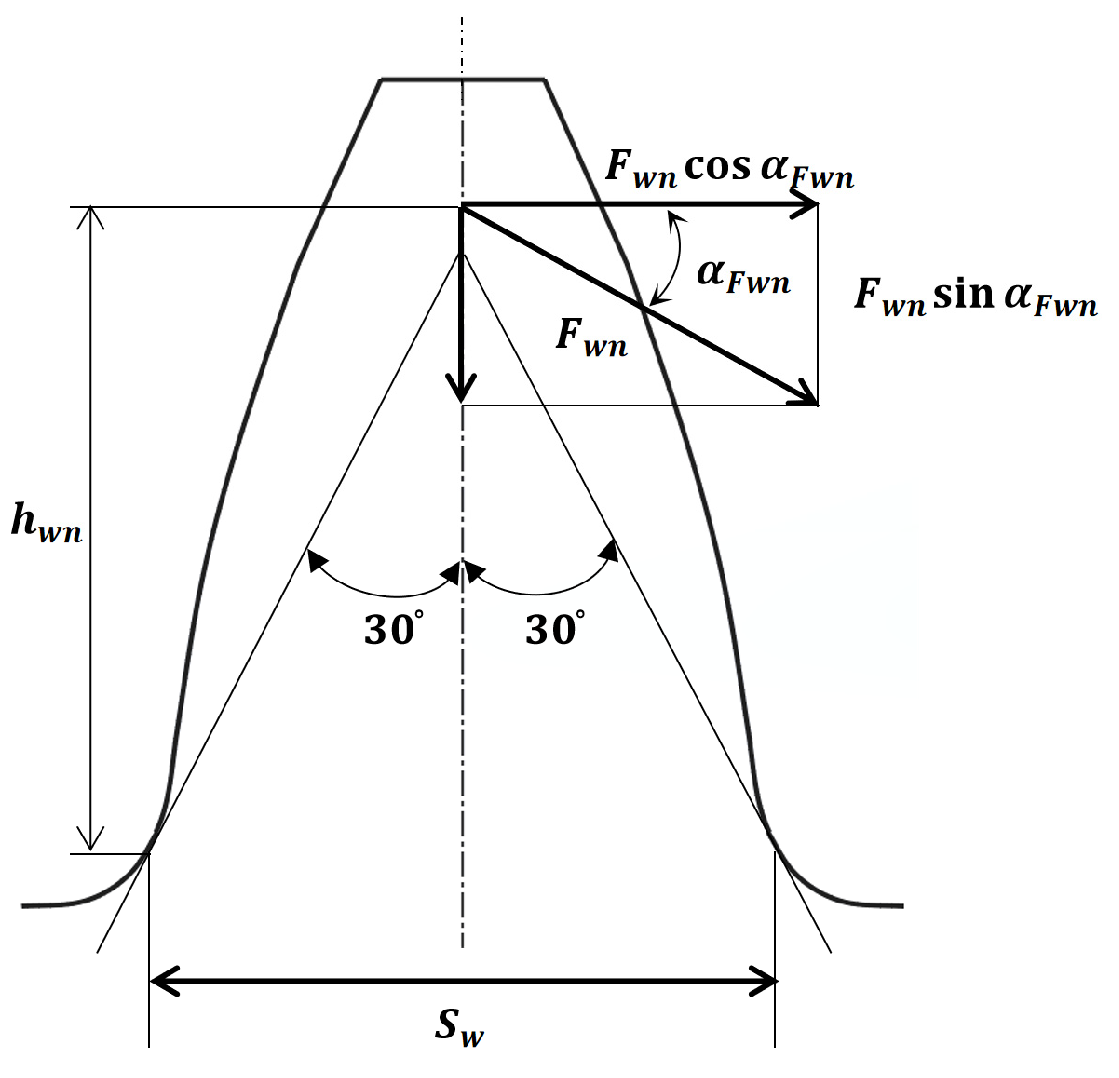
The situation regarding when the normal load F w n acts on a certain boundary point of the double-tooth meshing area is shown in Figure 1 (the subscript n represents various points of the double-tooth meshing area of the high-tooth gear pair, and the same also applies below). In the figure, α F w n is the pressure angle when the load acts on the boundary point position, and this normal load F w n can be decomposed into two components: F w n cos α F w n and F w n sin α F w n . The former generates bending tensile stress σ w n and shear stress τ w n at the dangerous section of the tooth root [33], while the latter generates compressive stress σ c n at the dangerous section. Therefore, the dangerous section of the tooth root will be subjected to a combination of bending tensile stress, shear stress, and compressive stress.
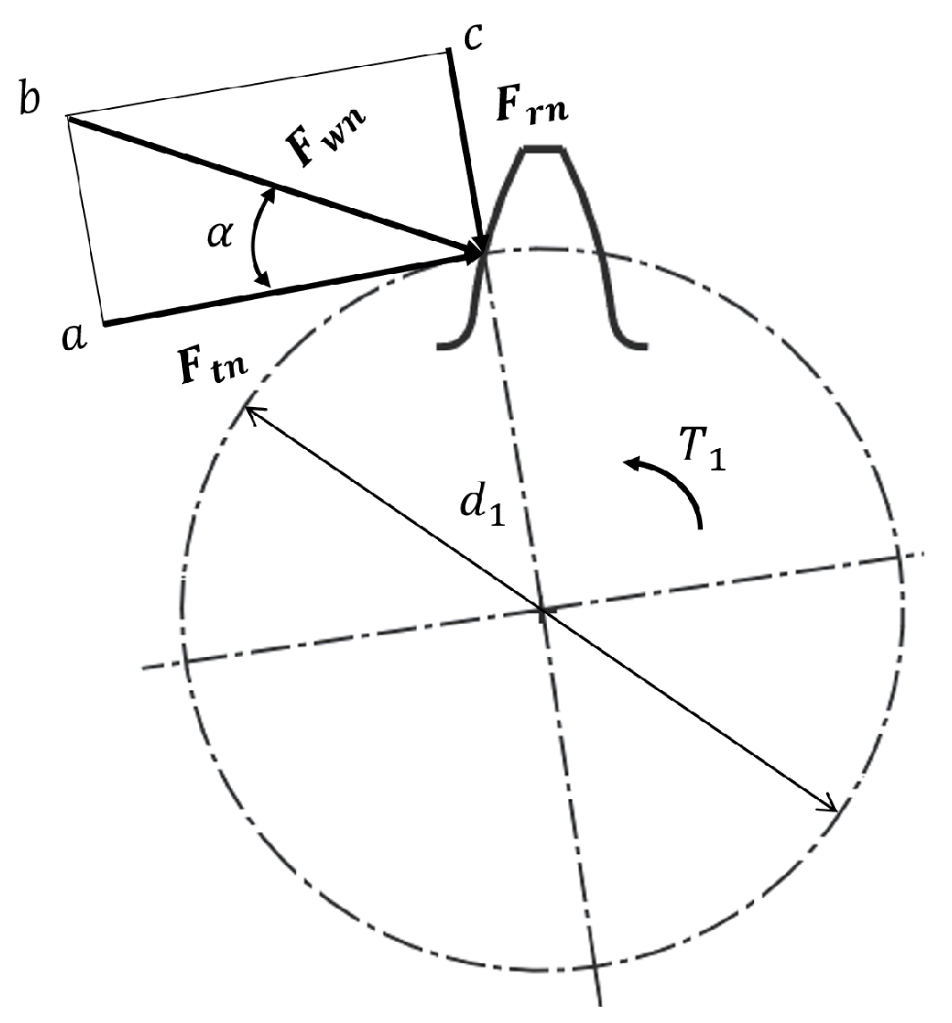
According to Figure 1 and Figure 2, the bending tensile stress at the dangerous section of the tooth root can be determined as follows:
σ w n = M W = F w n cos α F w n h w n b S w 2 6 = F t n cos α F w n h w n b S w 2 cos α 6
where h w n is the bending force arm at a certain loading boundary point of the high-tooth gear; s w is the tooth thickness at the dangerous section of the root of the high-tooth gear; and α is the indexing circle pressure angle of the high-tooth gear.
In Figure 2, d 1 is the diameter of the indexing circle. T 1 is the torque applied to the gear. F r n is the radial force, and F t n is the tangential force.
Transform Equation (1) to obtain:
σ w n = F t n b m · 6 ( h w n m ) cos α F w n ( s w m ) 2 cos α
In the formula, m is the modulus. Define the tooth shape coefficient Y F n at the boundary point of the high-tooth gear; then, obtain the effect of the tooth shape on the nominal bending stress when the load acts on the meshing boundary point of the double-tooth meshing zone.
Y F n = 6 ( h w n m ) cos α F w n ( s w m ) 2 cos α
Therefore, Equation (2) can be simplified as follows:
σ w n = F t n b m · Y F n
At present, various existing standards consider different types of stress when calculating the bending strength of tooth roots, resulting in different calculation formulas. According to GB and ISO, shear stress and compressive stress are relatively small, and they mainly consider the root bending stress of the gear teeth under the horizontal force of F w n cos α F w n ; this is then used as the basic stress for calculating the root bending strength. By introducing a stress correction coefficient Y S n , errors caused by ignoring shear stress and compressive stress can be adjusted. For gears with a tooth shape angle not equal to 20 ° , Y S n can be approximately calculated according to Formula (5):
Y S n = ( 1.2 + 0.13 L ) ( q s ) 1 1.21 + 2.3 / L
where L = S w / h w n , the root fillet coefficient is q s = S w / 2 ρ F ; and ρ F is the curvature radius at the 30 ° tangent point. The calculation formula will be introduced later.
Finally, the calculation formula for the bending strength of various points in the double-tooth meshing area of the high-tooth gear is obtained as follows:
σ w n = F t n b m · Y F n · Y S n
From Equation (6), it can be seen that the bending strength of the tooth root of the high-tooth gear is closely related to the load F t n borne by each pair of teeth in the double-tooth meshing area and the tooth shape coefficient Y S n at each meshing boundary point position. The load F t n is borne by each pair of teeth in the double-tooth meshing area being equal to the product of the total load F t and the load distribution rate q n , which is between the teeth in the meshing area. Next, we studied the load distribution in the double-tooth meshing area and the three-tooth meshing area of high-tooth gears.

2.2. Calculation of Load Distribution between the Teeth of a High-Tooth Gear Pair

Due to the high degree of contact ratios, double-tooth meshing and triple-tooth meshing were alternated between during the transmission process, and each tooth was affected by multiple parameters. At present, various standards have only studied the load distribution between the teeth of low-coincidence gears, and there is little discussion on the load distribution of high-coincidence gears.
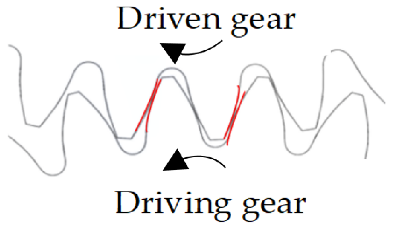
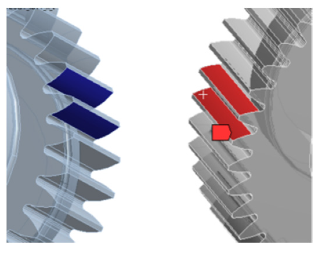
From Figure 3, it can be seen that the total load F t of the high-tooth gear in the double-tooth meshing area is borne by two pairs of high-tooth gear teeth simultaneously. Assuming that these two pairs of gear teeth share the load F t 21 and F t 22 , respectively, then
F t = F t 21 + F t 22
In Figure 3, the teeth marked with red lines represent the double-tooth meshing state.
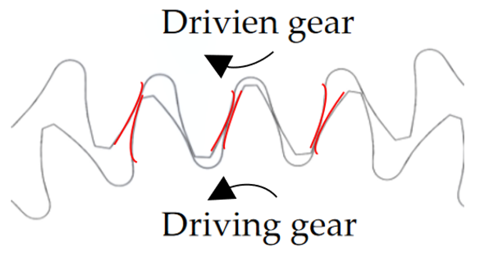
From Figure 4, it can be seen that the total load F t of a high-tooth gear in the triple-tooth meshing area is shared by three pairs of high-tooth gears. Assuming that these three pairs of gear teeth share the load   F t 31   ,   F t 32 , and F t 33 then
F t = F t 31 + F t 32 + F t 33
In Figure 4, the teeth marked with red lines represent the three-tooth meshing state.
Based on ISO standards, the load distribution rate q n between the teeth in the different meshing areas of high-tooth gears is defined as the percentage of the total load borne by a single-gear tooth in different meshing areas.
Based on ISO standards, the transmission error T d in the transmission process of high-tooth gears is defined as the deviation of the actual transmission position of the high-tooth gears from the theoretical transmission position. The expression is as follows:
T d = F i K i + δ i + Δ i
where
F i is the load borne by the i -th pair of teeth;
K i is the stiffness of the i -th pair of teeth;
δ i is the modification amount of each meshing gear tooth;
Δ i is the equivalent meshing error of the base pitch deviation, tooth orientation error, and tooth shape error of the gear.
The total deformation of each pair of gear teeth in different meshing regions should be equal, thus obtaining the gear deformation coordination formula. The deformation coordination formula for high-tooth gears in the double-tooth meshing area is as follows:
F t 21 K 21 + δ 21 + Δ 21 = F t 22 K 22 + δ 22 + Δ 22
Similarly, the deformation coordination formula for high-tooth gears in the triple-tooth meshing area is
F t 31 K 31 + δ 31 + Δ 31 = F t 32 K 32 + δ 32 + Δ 32 = F t 33 K 33 + δ 33 + Δ 33
The simultaneous use of Equations (7), (8), (10) and (11) can help with calculating the load borne by each pair of teeth in a high-tooth gear in the double-tooth meshing area and the triple-tooth meshing area. According to the definition of the load distribution rate between teeth, the load distribution rate of high-tooth gears in different meshing regions can be obtained.
Based on the above calculation, it can be inferred that the load borne by each pair of teeth in the double-tooth meshing zone is greater than that borne by each pair of teeth in the triple-tooth meshing area. According to the calculation of the bending strength of the low-coincidence gear root, the bending stress of the driving gear (pinion) root is greater than that of the driven gear root. Therefore, by only comparing the driving gears in different meshing regions, the final result is that the tooth root bending stress of the driving gear in the double-tooth meshing region is greater than that in the triple-tooth meshing region.

2.3. Calculation of the Tooth Profile Coefficients at Meshing Boundary Points of a High-Tooth Gear Pair

The processing methods for external meshing gear pairs currently include, in the main, rack tool processing and gear shaping processing. High-tooth gears are processed using rack and pinion cutting tools. This section mainly studies the tooth shape coefficients of various points in the double-tooth meshing area of high-tooth gears, as well as provides the calculation formulas for the tooth shape coefficients at each meshing boundary point.
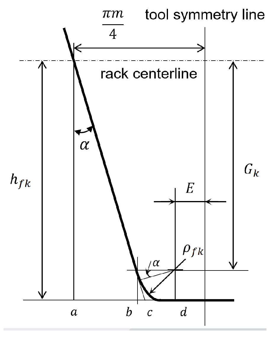
Figure 5 shows the basic tooth profile of the rack tool, where the distance E from the center of the tool tip to the symmetrical line of the tool is as follows:
E = π m 4 ( a c ¯ + b d ¯ b c ¯ )
By calculating the geometric relationships in Figure 5, it can be concluded that
E = π m 4 h f k tan α ρ f k cos α + ρ f k tan α
where
h f k is the tooth top height of the rack tool (corresponding to the tooth root height before gear modification) and ρ f k is the radius of the tooth tip fillet of the rack tool.
When introducing the hypothesis coefficient G and auxiliary calculation coefficient G k , we can obtain the following:
G k = h f k ρ f k x m
G = G k m = ρ f k m + x h f k m
where x is the radial displacement coefficient and x m is the radial displacement.
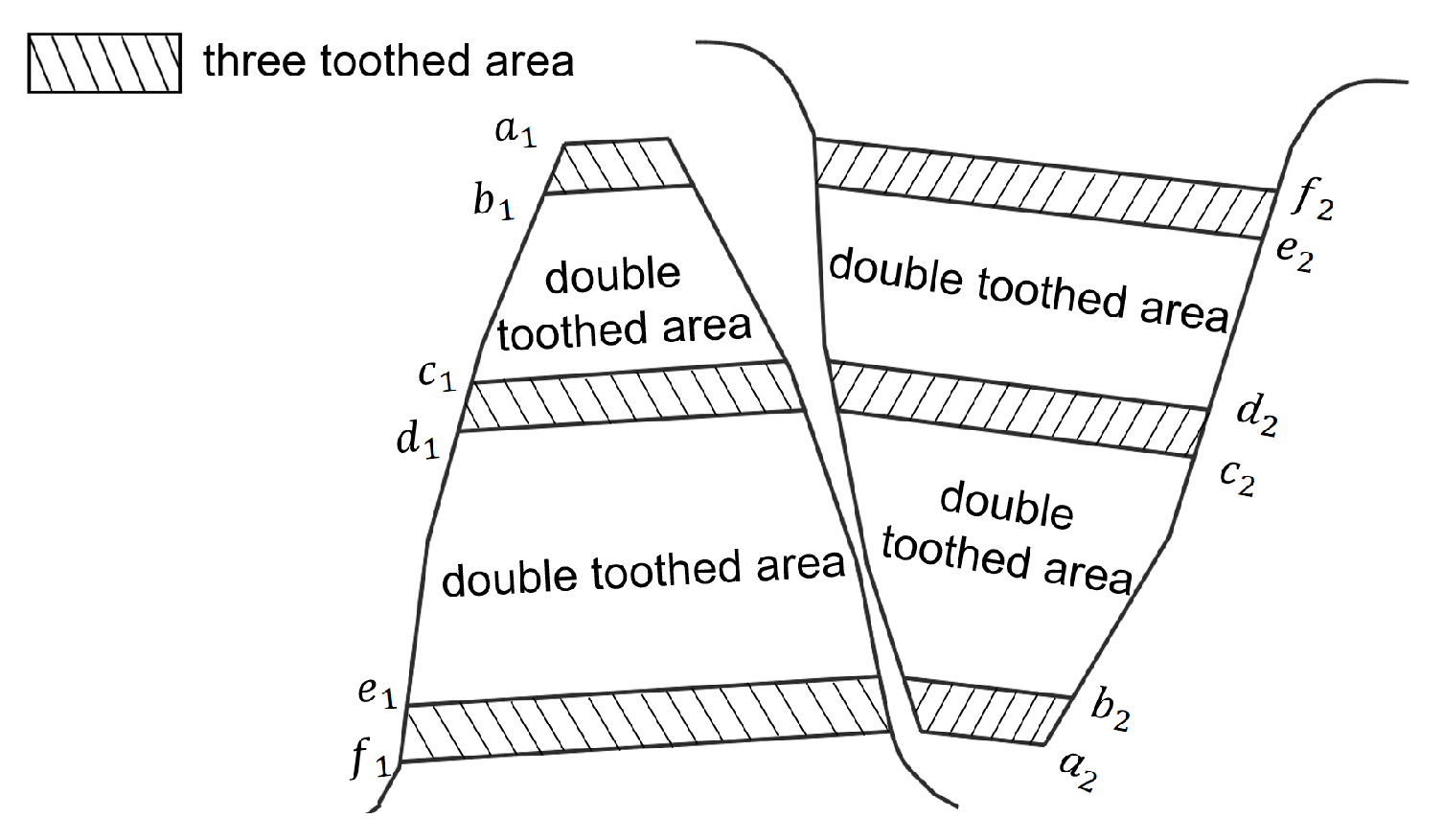
During the transmission process, the high-tooth gear pair will go through a double-tooth meshing zone and a triple-tooth meshing zone, as shown in Figure 6. The positions of various boundary points in different meshing zones are shown in Figure 6 and Figure 7.
In Figure 6, the high-tooth gear pair enters meshing from f 1 ( a 2 ) and disengages from meshing from a 1 ( f 2 ) . e , d , c , and b , which are the boundary points of the double-tooth meshing area, respectively. In
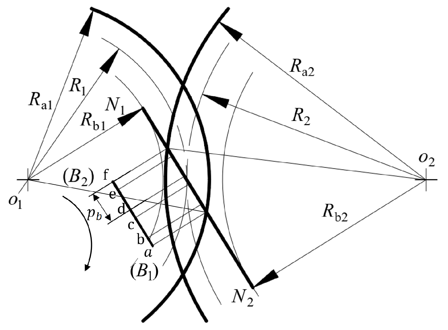
 Figure 7, N 1 N 2 ¯ is the theoretical meshing line length of the high-tooth gear pair; B 1 B 2 ¯ ( a f ¯ ) is the actual meshing line length of the high-tooth gear pair, according to the following definition:
B 1 B 2 ¯ = ε w · P b
where p b is the base circle tooth pitch and ε w is the contact ratio of the high-tooth gear transmission.
According to geometric relationships, the length of the meshing line at each meshing boundary point is as follows:
f e ¯ = a b ¯ = B 1 B 2 ¯ 2 P b = ε w 2 P b f d ¯ = a c ¯ = P b f c ¯ = a d ¯ = B 1 B 2 ¯ P b = ε w 1 P b f b ¯ = a e ¯ = B 1 B 2 ¯ ε w 2 P b = 2 P b
The theoretical meshing line length of the driving gear (pinion) is
a N 1 ¯ = ( R a 1 ) 2 ( R b 1 ) 2
In Δ O 1 N 1 e ,   Δ O 1 N 1 d ,   Δ O 1 N 1 c ,   Δ O 1 N 1 b , the diameter of each boundary point of the driving gear in the double-tooth meshing area can be obtained as follows:
d f e = 2 R f e = 2 a N 1 ¯ a e ¯ 2 + R b 1 2 = 2 R a 1 2 R b 1 2 2 P b 2 + R b 1 2 d f d = 2 R f d = 2 a N 1 ¯ a d ¯ 2 + R b 1 2 = 2 R a 1 2 R b 1 2 ε w 1 P b 2 + R b 1 2 d f c = 2 R f c = 2 a N 1 ¯ a c ¯ 2 + R b 1 2 = 2 R a 1 2 R b 1 2 P b 2 + R b 1 2 d f b = 2 R f b = 2 a N 1 ¯ a b ¯ 2 + R b 1 2 = 2 R a 1 2 R b 1 2 ε w 2 P b 2 + R b 1 2
The pressure angle corresponding to each boundary point of the driving gear in the double-tooth meshing area of the high-tooth gear pair is
{ α f e = cos 1 ( d b 1 / d f e ) α f d = cos 1 ( d b 1 / d f d ) α f c = cos 1 ( d b 1 / d f c ) α f b = cos 1 ( d b 1 / d f b )
The central angle corresponding to half of the tooth thickness at each boundary point of the driving gear in the double-tooth meshing area of the high-tooth gear pair (approximately calculated by using the arc length formula) is
γ f e = S f e R f e = 1 z 1 π 2 + 2 x tan α + inv α inv α f e γ f d = S f d R f d = 1 z 1 π 2 + 2 x tan α + inv α inv α f d γ f c = S f c R f c = 1 z 1 π 2 + 2 x tan α + inv α inv α f c γ f b = S f b R f b = 1 z 1 π 2 + 2 x tan α + inv α inv α f b
where S f e  is the half tooth thickness corresponding to the meshing boundary point e .
The end face load angle at each boundary point of the driving gear in the double-tooth meshing area of the high-tooth gear pair is as follows:
{ α w f e = α f e γ f e α w f d = α f d γ f d α w f c = α f c γ f c α w f b = α f b γ f b
According to ISO standards, the auxiliary angle θ is introduced to obtain the bending force arm at various points of the driving gear of the high-tooth gear pair as follows:
h w n = [ d f n ( cos γ f n sin γ f n tan α w f n ) z 1 m cos ( π 3 θ ) G m cos θ + ρ f k ] 2
where the subscript n represents the boundary points e , d , c , and   b of the double-tooth meshing zone of the high-tooth gear pair. The auxiliary angle θ is as follows:
θ = 2 G z 1 tan θ 2 z 1 ( π 2 E m ) + π 3
Then, solve θ according to Newton’s method and take its initial value as
θ = 1 ( 1 2 G / z 1 ) [ π 3 2 z 1 ( π 2 E m ) ]
The formula for calculating the curvature radius ρ F at the tangent point 30 ° of the driving gear root of a high-tooth gear pair is
ρ F = ρ f k + 2 m G 2 cos θ [ z 1 ( cos θ ) 2 2 G ]
The position of the dangerous section at the tooth root is determined by the 30 ° tangent method, which is the plane where the two tangent points connect the symmetrical line of the tooth and form a 30 ° and tangent line to the transition fillet of the tooth root, which forms a straight line. This plane is independent of the position of the load application point. Therefore, according to ISO standards, the tooth thickness S w of the dangerous section of the tooth root of the high-tooth gear pair can be obtained as follows:
S w = z 1 m sin ( π 3 θ ) + 3 m ( G cos θ ρ f k m )
By substituting the parameters of each boundary point in the double-tooth meshing area of the high-tooth gear pair into Equation (3), the tooth shape coefficient of the driving gear can be obtained. Similarly, the tooth shape coefficient of the driven gear can also be obtained.

3. The FEA of the Bending Strength of the Tooth Root of a High-Tooth Gear Pair

At present, the method of using finite element analysis to analyze the stress of gears is relatively mature. In this section, an ANSYS Workbench was used to analyze the maximum root bending stress for high-tooth gear pairs. The specific process is shown in Figure 8.
The following will provide a detailed introduction to each part of the flowchart.

3.1. Basic Parameters and Material Properties of High-Tooth Gear Pair

The basic parameters of the high-tooth gear pair are shown in Table 1.
The high-tooth gear pair was made of 20 GrMnTi material, and the specific material parameters are shown in Table 2.

3.2. Finite Element Model Establishment and Mesh Generation

Maidi 3D software was used to model the gear according to the parameters in Table 1, as shown in Figure 9.
The high-tooth gear pair was made of 20 GrMnTi materials, and its material properties were defined in ANSYS software according to Table 2; it was then added to the finite element solution model.
In addition to the global coordinate system, a local cylindrical coordinate system for the driving gear was added, as shown in Figure 10. In the figure, the Y-axis represents its rotational degree of freedom. The X and Z axes represent degrees of freedom in other directions.
In the pretreatment process of FEA, the quality of the mesh division directly affects the accuracy of the solution results. Compared with tetrahedral grids, hexahedral grids have fewer segmentation quantities and faster computational speed. To ensure calculation accuracy, mesh density was applied to the gear tooth contact surface and its surrounding area, and relatively larger grids were used for positions other than the meshing position in order to reduce computational complexity.
This analysis sets the mesh size of the meshing tooth surface and its surrounding area to 0.5 mm. As the distance from the gear meshing position increases, the mesh size divided gradually increases, and the maximum mesh size in the model is 1 mm. The analysis model grid is shown in Table 3.
The grid division results, and local enlarged view are shown in Figure 11.
Due to the fact that the quality of the grid division directly affects the accuracy of the analysis results, it is crucial to evaluate the quality of the grid division and to measure it with the ‘Average Element Quality value’. With a reference value range of 0.5 ~ 1 , the grid division quality was 0.75. Additionally, in order to upgrade computational accuracy, we used quadratic elements with intermediate nodes. The element types are SOLID186 and SOLID187. This type of element has the traits of a large number of nodes, high discretization accuracy, and a continuous boundary stress for the element.
Based on the actual meshing situation of the high-tooth gear pair, the contact area was set, with face-to-face contact, as the tooth contact surface of the driving gear and the driven gear. Due to the bending stress of the tooth root in the double-tooth meshing area being greater than that in the triple-tooth meshing area, two pairs of tooth contact surfaces were set up. The contact type was defined as the frictional contact, with a friction coefficient set to 0.05, where ‘Target Bodies’ was the contact surface of the driving gear teeth—represented in blue—and ‘Contact Bodies’ was the contact surface of the driven gear teeth—represented in red—as shown in Figure 12.
Due to certain errors in gear modeling, there may be gaps in the initial meshing position of the meshing gear pair during analysis. Setting ‘Interface Treatment’ to ‘Adjust to Touch’ can automatically adjust the initial gap.
During the actual transmission process, the high-tooth gear pair only maintains rotational motion, such that, when conducting finite element simulation, it is necessary to define gear constraints. These constraints range from choosing to apply fixed constraints to the inner tooth surface of the driven gear; selecting the inner tooth surface of the driving gear to apply displacement constraints, retaining only the rotational degrees of freedom on the Z-axis; and applying torque to the inner tooth surface of the driving gear. These are shown in Figure 13.

3.3. Analysis of Simulation Results

In Figure 14, the maximum principal stress distribution at the tooth root when a torque of 500 N · m is applied to the inner tooth surface of the driving gear of a high-tooth gear pair, and when the tooth root stress of the gear pair reaches its peak within a meshing cycle, is shown. From the figure, it can be seen that the maximum bending stress occurs near the midpoint of the tooth width.
Considering the reliability of the stress results, we conducted a sensitivity analysis on the grid, and the analysis results are shown in Table 4.
As can be referred from Table 4, when the grid size is less than 0.5 mm, the change in bending stress at the root of the gear pair is no longer significant; however, the time used for analysis almost doubles, resulting in very low efficiency. In summary, we believe that the stress results that are obtained by a simulation analysis when using a mesh size of 0.5 mm near the tooth root are reliable.
At the same time, a certain number of nodes are taken along the width direction of the active gear teeth to obtain the distribution pattern of the tooth root bending stress along the width direction, as shown in Figure 15. From the figure, it can be seen that in the absence of bias load, the tooth root bending stress presents a symmetrical distribution along the width direction of the teeth.
In Figure 16, different torques are applied to the inner tooth surface of the driving gear of the high-tooth gear pair to obtain the maximum tooth root bending stress of the driving gear and the driven gear. In addition, the FEA results that were compared with the theoretical calculation results are also shown. In the figure, the FEA results of the tooth root bending stress are all smaller than the theoretical calculation results; this is because when using the finite element model for static analysis, it is impossible to guarantee that the initial meshing position is exactly the position of the boundary point.
The results show that under a low load, the error between the theoretical calculation value of the driving gear and the finite element results is between 8.3~13.53%, and the error between the theoretical calculation value of the driven gear and the finite element results is between 9.45 ~ 15.42 % . Under high loads, the error between the theoretical calculation value and the finite element result is between 7.45 ~ 8.78 % , and the error between the theoretical calculation value of the driven gear and the finite element result is between 8.21 ~ 10.91 % . From these data, it can be seen that when the load is high, the theoretical calculation values are closer to the FEA results.

4. Analysis of the Influence of Gear Parameters on the Bending Strength of Tooth Roots

The high-tooth gear pair increases the contact ratio by increasing the addendum height coefficient, as well as by reducing the pressure angle and reducing the modulus, so as to improve the bearing capacity of the gear [34,35]. In this section, many pairs of high-tooth gear pairs are designed by controlling variables, and the influence of different pressure angles, different tooth heights, and different tooth thicknesses on the bending strength of the tooth root of the high-tooth gear pair is specifically studied by using the finite element method.

4.1. Gear Parameters and Contact Ratio

The relationship between the contact ratio of the high-tooth gear pair and the gear parameters such as pressure angle α and addendum height coefficient h a * can be expressed by formulas. Thus, we can express this via the formula for calculating the gear contact ratio in ISO 6336:
ε w = [ z 1 ( tan α a 1 tan α ) + z 2 ( tan α a 2 tan α ) ] 2 π
where α a 1 , α a 2 —the pressure angle of the driving gear and the driven gear tooth tip circle, respectively;   α   —the meshing angle.
The calculation formula of addendum circle pressure angle is as follows:
cos α a = d b d a = d b d + 2 h a * · m
Furthermore, the calculation formula for the meshing angle is as follows:
inv α = 2 tan α ( x 1 + x 2 ) z 1 + z 2 + inv α

4.2. Model Establishment and Analysis

On this basis, according to the parameters of the high-tooth gear pair given in Table 1, the different tooth profiles are designed by changing, in turn, the addendum coefficient, pressure angle, and the changing trend of the tooth root bending strength of different tooth profile gears under a 500 N · m load.
Changing the tooth’s top height coefficient of a high-tooth gear pair will have a certain impact on its overlap, as shown in Figure 17.
The results show that there is a linear relationship between the gear coincidence degree and the tooth’s top height coefficient. When the tooth’s top height coefficient is around 1.19 , the coincidence degree is below 2, and it is no longer in the range of a high-coincidence degree. In Figure 18, the bending stress of the driven gear tooth root is lower than that of the driving gear tooth root. When the tooth’s top height coefficient is between 1.25 ~ 1.40 , the bending stress of the tooth root significantly decreases, i.e., the fatigue strength of the tooth root bending increases with the increase in the tooth’s top height coefficient.
It can be seen from Figure 19 and Figure 20 that changing the pressure angle of the high-tooth gear pair will not only have a certain impact on its contact ratio, but will also have a certain impact on its addendum circle tooth thickness. With an increase in the pressure angle, the gear pair contact ratio basically presents a linear decreasing trend. The tooth thickness of the addendum circle of the gear pair is negatively correlated with the pressure angle and decreases with the increase in the pressure angle.
As shown in Figure 21, when the pressure angle is less than 18 ° (with an increase in the pressure angle), the tooth root bending stress of the driving gear and the driven gear shows an increasing trend; thus, the tooth root bending strength decreases. When the pressure angle is about 18 ° ~ 19 ° , the tooth root bending stress changes slowly. When the pressure angle is greater than 19 ° , the coincidence degree is less than 2, and it is no longer in the range of the high-tooth gear that has a high contact ratio.
To summarize, the improvement of the contact ratio of the high-tooth gear pair is mainly achieved by changing the gear parameters: on the one hand, an increase in the pressure angle will lead to a decrease in the contact ratio and the tooth thickness of the addendum circle, which will lead to the decrease in the bending strength of the tooth root. On the other hand, increasing the coefficient of the tooth’s top height will lead to an increase in overlap, and the bending strength of the tooth root will also increase. Based on the above analysis, it is clear that with an increase in the overlap degree of the high-tooth gear pair, the bending strength of its tooth root shows an increasing trend.

5. Conclusions

This article focuses on the calculation method of the tooth root bending stress of high-coincidence high-tooth gear pairs, and it also estimates the influence of gear parameters on tooth root bending stress:
(1)
Based on the ISO standard method for calculating the bending stress of the tooth root of low-coincidence gear pairs, the boundary point of the double-tooth meshing area of the high-tooth gear pair is used as the loading point of the load. The calculation method for the load distribution in the double-tooth meshing area of the high-coincidence high-tooth gear pair, the calculation method for the tooth shape coefficient, and the tooth root bending stress at different meshing boundary points are derived;
(2)
Under various load conditions, the root bending stress and stress distribution along the tooth direction of a high-tooth gear pair were analyzed using ANSYS FEA. The results of the FEA were compared with the theoretical calculation values. The results showed that the deviation of the theoretical calculation values was smaller under high-load conditions compared to lower-load conditions. At the same time, if the influence of an eccentric load was not considered, the bending stress at the tooth root was symmetrically distributed along the tooth width, and the maximum bending stress appeared in the middle of the tooth width. This verifies the correctness of the calculation method;
(3)
By changing the pressure angle, addendum height coefficient, and other gear parameters to design different tooth profiles, this paper attempted to explore the law of tooth root bending stress changes with the tooth profile of the high-tooth gear pair. It displayed that increasing the pressure angle will lead to a decrease in the tooth root bending strength. The increase in addendum height coefficient will lead to an increase in the tooth root bending strength. Furthermore, the change in pressure angle and addendum height coefficient will affect the contact ratio, which is of utmost importance for the engineering design of high-tooth gears.

Author Contributions

Conceptualization, H.W. (Haiwei Wang) and J.Z.; methodology, J.Z.; software, J.Z.; validation, Y.L., Z.L. and S.H.; formal analysis, Y.L.; investigation, H.W. (Huan Wang); resources, H.W. (Haiwei Wang); data curation, S.H.; writing—original draft preparation, J.Z.; writing—review and editing, H.W. (Huan Wang). All authors have read and agreed to the published version of the manuscript.

Funding

This research was funded by the Key Research and Development Plan Project of Shaanxi Province (2021ZDLGY12-03).

Data Availability Statement

The data presented in this study are available on request from the corresponding author. The data are not publicly available due to restrictions, e.g., privacy or ethical.

Conflicts of Interest

The authors declare no conflict of interest.

References

  1. Kan, K.; Binama, M.; Chen, H.; Zheng, Y.; Zhou, D.; Su, W.; Muhirwa, A. Pump as turbine cavitation performance for both conventional and reverse operating modes. Renew. Sustain. Energy Rev. 2022, 168, 112786. [Google Scholar] [CrossRef]
  2. Kan, K.; Zhang, Q.; Zheng, Y.; Gao, Q.; Shen, L. Energy loss mechanism due to tip leakage flow of axial flow pump as turbine under various operating conditions. Energy 2022, 255, 124532. [Google Scholar] [CrossRef]
  3. Dudley; Yu, M. Comparison of two standards for calculating the load carrying capacity of involute cylindrical gears. Gear 1985, 5, 36–38. [Google Scholar]
  4. Wu, C.; Lv, Y. Comparison of ISO and AGMA involute cylindrical gear strength calculation standards. China Mech. Eng. 2011, 22, 1418–1423. [Google Scholar]
  5. Zhou, C.; Tang, J.; Liu, Y.; Liu, J. Comparative study of two calculation standards for gear transmission design. Mech. Transm. 2006, 3, 9–10. [Google Scholar]
  6. Zhou, C.; Long, J.; Wang, H.; Tang, J. Comparison and finite element verification of ISO and AGMA standards for contact and bending strength of spiral bevel gears. J. Hunan Univ. (Nat. Sci. Ed.) 2018, 45, 1–9. [Google Scholar]
  7. Zhu, Z.; Cui, H.; Gong, M.; Bao, H.; Zhu, R. Contact stress analysis of external non-variable multi-modulus spur gear pairs. J. Aerosp. Eng. 2023, 09544100231167904. [Google Scholar] [CrossRef]
  8. Zorko, D.; Duhovnik, J.; Tavcar, J. Tooth bending strength of gears with a progressive curved path of contact. J. Comput. Des. Eng. 2021, 8, 1037–1058. [Google Scholar] [CrossRef]
  9. Sun, Q.; Sun, Y.; Li, L. Strength analysis and tooth shape optimization for involute gear with a few teeth. Adv. Mech. Eng. 2018, 10, 1687814017751957. [Google Scholar] [CrossRef]
  10. Müller, D.; Stahl, J.; Nürnberger, A.; Golle, R.; Tobie, T.; Volk, W.; Stahl, K. Shear cutting induced residual stresses in involute gears and resulting tooth root bending strength of a fineblanked gear. Arch. Appl. Mech. 2021, 91, 3679–3692. [Google Scholar] [CrossRef]
  11. Liang, B.; Liang, G. The application of boundary element method in the calculation of gear bending strength. Mech. Design. 1988, 3, 7–12+62. [Google Scholar]
  12. Filiz, I.H.; Eyercioglu, O. Evaluation of gear tooth stresses by finite element method. J. Eng. Industry. 1995, 117, 232–239. [Google Scholar] [CrossRef]
  13. Chen, X.S.; Tang, J.Y.; Chen, S.Y.; Fu, Z.H. Experimental study and finite element verification of bending stress in modified gears. Mech. Transm. 2018, 42, 97–101. [Google Scholar]
  14. Mo, S.; Ma, S.; Jin, G. Research on composite bending stress of asymmetric gear in consideration of friction. J. Mech. Eng. Sci. 2019, 233, 2939–2955. [Google Scholar] [CrossRef]
  15. Tu, W.B.; Yang, J.W.; Luo, Y.; Ren, J.W. Finite element analysis of bending strength during gear meshing process. Mech. Eng. Autom. 2018, 6, 48–50. [Google Scholar]
  16. Xue, Y.T.; Zhao, G.; Wang, A.Z.; He, C. Geometric analysis of bending strength and other factors of spur gears. J. Graph. 2022, 43, 79–84. [Google Scholar]
  17. Cui, G.; Fan, Y. Design and analysis of gear conjugate tooth profile based on sinusoidal reference tooth profile. Mach. Design. 2015, 39, 59–62. [Google Scholar]
  18. Li, J.; Li, H.C.; Wang, W.C.; Li, K.K.; Guo, D.N. Gear strength verification and stress simulation analysis of high pressure aviation fuel gear pumps. Hydraul. Pneum. 2021, 2, 105–113. [Google Scholar]
  19. Xianbo, Z. High Strength Gear Design; Mechanical Industry Press: Beijing, China, 1981. [Google Scholar]
  20. Fang, Z.; Jiang, X.; Song, J. Research on the performance of high coincidence gears. Gears 1987, 1, 27–32. [Google Scholar]
  21. Zhuang, Z. Discussion on the design and application of “high tooth gear” gears. Automot. Gears 2008, 2, 1–7. [Google Scholar]
  22. Li, S. Effect of addendum on contact strength, bending strength and basic performance parameters of a pair of spur gears. Mech. Mach. Theory. 2008, 43, 1557–1584. [Google Scholar] [CrossRef]
  23. Pedersen, N. Minimizing tooth bending stress in spur gears with simplified shapes of fillet and tool shape determination. Eng. Optim. 2015, 47, 805–824. [Google Scholar] [CrossRef]
  24. Bai, G.Q.; Wang, T.; Zhang, R.L.; Zhao, F.Q. Optimization and simulation analysis of the tooth profile of fine high toothed gears. Mech. Transm. 2012, 5, 46–48. [Google Scholar]
  25. Li, F. Research on the Strength and Dynamics of High Fit Planetary Gear Transmission System. Ph.D. Thesis, Nanjing University of Aeronautics and Astronautics, Nanjing, China, 2015. [Google Scholar]
  26. Raut, A.; Khot, S.; Salunkhe, V. Optimization of geometrical features of spur gear pair teeth for minimization of vibration generation. J. Vib. Eng. Technol. 2023, 1–13. [Google Scholar] [CrossRef]
  27. Concli, F.; Maccioni, L.; Fraccaroli, L.; Cappellini, C. Effect of gear design parameters on stress histories induced by different tooth bending fatigue tests: A numerical-statistical investigation. Appl. Sci. 2022, 12, 3950. [Google Scholar] [CrossRef]
  28. Concli, F.; Fraccaroli, L.; Maccioni, L. Gear root bending strength: A new multiaxial approach to translate the results of single tooth bending fatigue tests to meshing gears. Metals 2021, 11, 863. [Google Scholar] [CrossRef]
  29. Wang, Y.; Liu, P.; Dou, D. Investigation of load capacity of high-contact-ratio internal spur gear drive with arc path of contact. Appl. Sci. 2022, 12, 3345. [Google Scholar] [CrossRef]
  30. Concli, F.; Maccioni, L.; Fraccaroli, L.; Bonaiti, L. Early crack propagation in single tooth bending fatigue: Combination of finite element analysis and critical-planes fatigue criteria. Metals 2021, 11, 1871. [Google Scholar] [CrossRef]
  31. Flek, J.; Dub, M.; Kolář, J.; Lopot, F.; Petr, K. Determination of mesh stiffness of gear—Analytical approach vs. FEM analysis. Appl. Sci. 2021, 11, 4960. [Google Scholar] [CrossRef]
  32. Fontanari, V.; Molinari, A.; Marini, M.; Pahl, W.; Benedetti, M. Tooth root bending fatigue strength of high-density sintered small-module spur gears: The effect of porosity and microstructure. Metals 2019, 9, 599. [Google Scholar] [CrossRef] [Green Version]
  33. Pu, L.; Ji, M. Mechanical Design; Beijing Higher Education Press: Beijing, China, 2006. [Google Scholar]
  34. Sun, H.; Chen, Z. Mechanical Principle; Beijing Higher Education Press: Beijing, China, 2013. [Google Scholar]
  35. Zhang, L. Optimization Design and Dynamic Analysis of High-Tooth Gears. Master’s Thesis, Beijing University of Technology, Beijing, China, 2017. [Google Scholar]
Figure 1. Force on the gear tooth at a boundary point.
Processes 11 01807 g001
Figure 2. Stress analysis of the high-tooth gear.
Processes 11 01807 g002
Figure 3. Double-tooth meshing state.
Processes 11 01807 g003
Figure 4. Three-tooth meshing state.
Processes 11 01807 g004
Figure 5. Basic tooth profile of a rack tool.
Processes 11 01807 g005
Figure 6. Meshing area of a high-tooth gear pair.
Processes 11 01807 g006
Figure 7. Location of meshing boundary points.
Processes 11 01807 g007
Figure 8. Analysis method flowchart based on FEA.
Processes 11 01807 g008
Figure 9. High-tooth gear pair model.
Processes 11 01807 g009
Figure 10. Cylindrical coordinate system.
Processes 11 01807 g010
Figure 11. Grid division view.
Processes 11 01807 g011
Figure 12. Contact surface of the high-tooth gear pair.
Processes 11 01807 g012
Figure 13. Boundary constraints.
Processes 11 01807 g013
Figure 14. Stress distribution cloud diagram. (a) Driving gear. (b) Driven gear.
Processes 11 01807 g014
Figure 15. Tooth bending stress distribution.
Processes 11 01807 g015
Figure 16. Comparison between theoretical calculation and FEA.
Processes 11 01807 g016
Figure 17. Coefficient of the addendum and contact ratio.
Processes 11 01807 g017
Figure 18. The coefficient of the addendum and tooth root bending stress.
Processes 11 01807 g018
Figure 19. Pressure angle and contact ratio.
Processes 11 01807 g019
Figure 20. The pressure angle and tooth thickness of the addendum circle.
Processes 11 01807 g020
Figure 21. The pressure angle and tooth root bending stress.
Processes 11 01807 g021
Table 1. Parameters of the high-tooth gear.
Pressure Angle
( ° )
Modulus
(mm)
Number of TeethThe Modification CoefficientAddendum Height
(mm)
Total Tooth Height
(mm)
Tooth Width
(mm)
Driving gear182.3330.3003.5446.46529
Driven gear182.346−0.0082.9966.46525
Table 2. Material parameters of the high-tooth gear.
Density
( k g / m 3 )
Poisson’s RatioYoung’s Modulus
(Pa)
Tensile Strength
(Pa)
Yield Strength
(Pa)
Thermal Expansion Coefficient
( 1 / )
7.86 × 10 3 2.89 × 10 1 2.12 × 10 11 1.08 × 10 9 8.35 × 10 8 1.27 × 10 5
Table 3. Grid Properties.
Number of Grids
(Thousand)
Number of Grid Nodes
(Thousand)
Contact Area Size
(mm)
Maximum Grid Size
(mm)
Minimum Grid Size
(mm)
490.0641803.5690.510.5
Table 4. Grid sensitivity analysis.
Grid Size at Tooth Root
(mm)
Grid Division QualityRoot Bending Stress of Driving Gear
(Mpa)
Root Bending Stress of Driven Gear
(Mpa)
Time
(min)
0.70.739488.22484.5714:14
0.60.732496.26485.5413:23
0.50.754490.6487.0111:03
0.40.751488.72486.6321:20
0.30.747490.34486.9220:30
Disclaimer/Publisher’s Note: The statements, opinions and data contained in all publications are solely those of the individual author(s) and contributor(s) and not of MDPI and/or the editor(s). MDPI and/or the editor(s) disclaim responsibility for any injury to people or property resulting from any ideas, methods, instructions or products referred to in the content.

