Article

Making a Soft Elastic Pulsation Pump (SEPP)

1
Life Quality Engineering Interest Group, School of Chemical Engineering and Environmental Engineering, Soochow University, Suzhou Industrial Park, Suzhou 215123, China
2
School of Medicine, Tsinghua University, Beijing 100084, China
*
Authors to whom correspondence should be addressed.
Processes 2023, 11(5), 1581; https://doi.org/10.3390/pr11051581
Submission received: 25 April 2023 / Revised: 12 May 2023 / Accepted: 16 May 2023 / Published: 22 May 2023
(This article belongs to the Special Issue Design and Optimization Method of Pumps)

Abstract

:
In this work, a soft-elastic pulsation pump (SEPP) has been made and investigated. Here, 3D printing was used to make casting molds and a melt-removal method using wax was employed. The SEPP was made of silicone rubber and driven by an external squeezing mechanism. A silicone one-way valve was also made which prevented backflow after the fluid was squeezed out of the pump chamber. The material characteristics of the SEPP including durability were examined. The pump operating parameters were confirmed to differential pressure of 100 mm Hg in a close flow loop. The average flow rate was 2 L/min, while yielding a peak flow of 8 L/min, and a stroke volume of 70 mL. A preliminary trial using fresh animal blood had shown that the SEPP has good protection on the blood. Therefore, within the resources available, an interesting idea for an effective SEPP has been proposed and realized in the laboratory. The technical details of the SEPP described, and the experimental results reported here form a good basis for making higher capacity SEPPs. This effort may help make its way to an effective ventricular assist device.

1. Introduction

The current work, though far away from a realistic application, was inspired by the ventricular assist device (VAD). A design approach was taken to make a soft-elastic pump which has distinct pulsing characteristics.
It is general knowledge that heart transplantation is a gold standard for the treatment of end-stage heart failure. Due to an insufficient number of heart donors, patients who need heart transplantation can only take conservative treatment and indeed may lose their lives at any time [1]. An artificial heart pump is a device that powers human blood circulation temporarily. It is expected that it can help patients to stay alive while waiting for a heart transplant. For some patients, it can also be used as an ultimate treatment, i.e., when a heart transplant is not available or when an artificial system is good enough to replace the actual heart. Since the twentieth century, artificial heart pumps have undergone several technological innovations. They gradually become smaller, lighter, have good hemolytic properties, and stable performance. There are, however, problems such as hemolysis and thrombosis [2,3,4]. The occurrence of these problems is related to the high shear force and long exposure time of the blood in the pump. Essentially it is undesirable that the red blood cells are exposed to high shear for long periods. Due to the fragility of the cell membrane, the risk of hemolysis caused by red blood cell fragmentation is always present [5,6,7,8,9]. The transport phenomena created in the structure of an artificial heart pump are important, influencing the hydraulic performance and thus the hemolytic performance [10].
Copeland et al. believed that the surplus hemodynamic energy of a pulsatile pump is much higher than that of a continuous pump [11]. The extra energy of each pulse seems to be an advantage. As physiological conditions change, the microcirculation may require this additional energy to maintain adequate capillary flow [11]. Sunagawa et al. suggested that the use of pulsatile flow improves end-organ function compared to non-pulsatile flow [12].
A pulsatile pump is considered to be more in line with human biology. In addition, more applications of 3D printing technology in artificial heart development have been reported in the literature, which facilitate the fabrication of cavities of complex geometries [13,14,15,16]. In 2017, Cohrs et al. first proposed a pneumatically actuated flexible artificial heart with a flow rate of 2.2 L/min when operated at 80 bpm [17]. In 2021, Guex et al. fabricated a pneumatically actuated flexible artificial heart by injection molding [18]. Both of the above devices transport liquid through expansion and contraction of the internal expansion chambers of the artificial heart which could cause a sharp increase in local shear stress which is not desirable for blood protection.
In recent years, some interesting fluid rolling robots have been developed which use voltage-driven oscillating liquids and eccentric soft actuators driven by stacked electrohydrodynamic pumps to mimic muscles [19,20] These new technologies may be expected to be used for artificial heart applications. For the time being, however, no such report can be found.
In this study, a robust soft elastic pulsation pump (SEPP) relevant to the development of a future prototype VAD has been devised. A soft-elastic chamber (the Bread) has been made and optimized to an extent. A non-return valve was designed and made which enables the flow forward after each squeezing pulse. The mock fluid loop was established using non-blood fluids and, in one case, using fresh pig blood. The results have demonstrated that the N.I.H. after 6 h was only 0.006356, below the standard value of 0.01.
The material which constitutes the device has been tested for durability which has shown great potential for practical application. Though the current device is small in capacity compared with a usual VAD, the principle is not limited to the current size as it can be enlarged in the future.

2. Materials and Methods

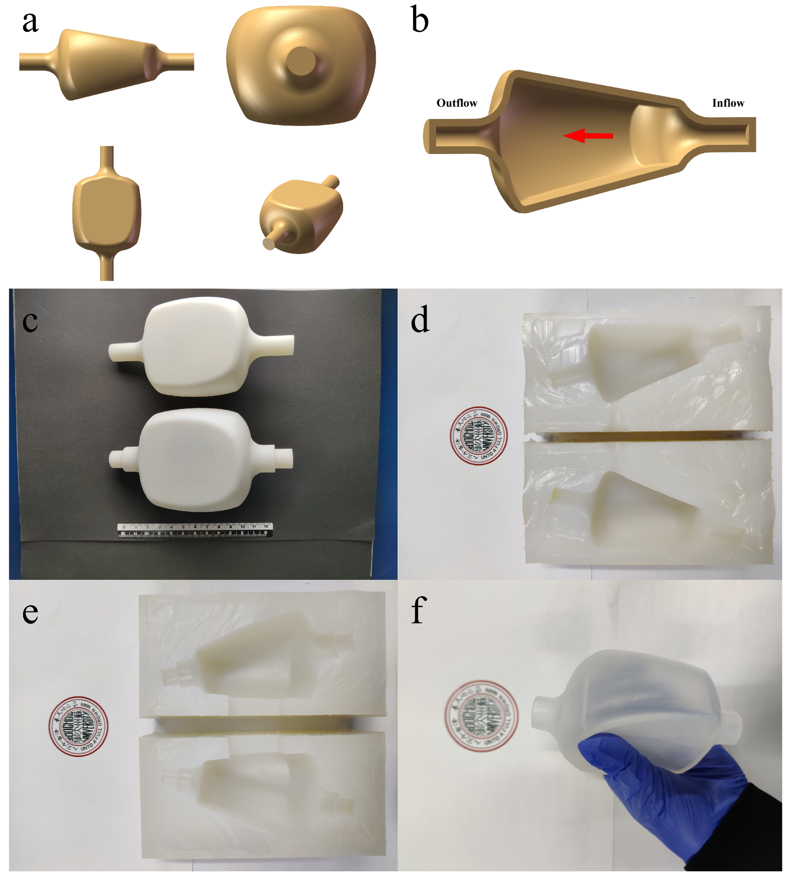
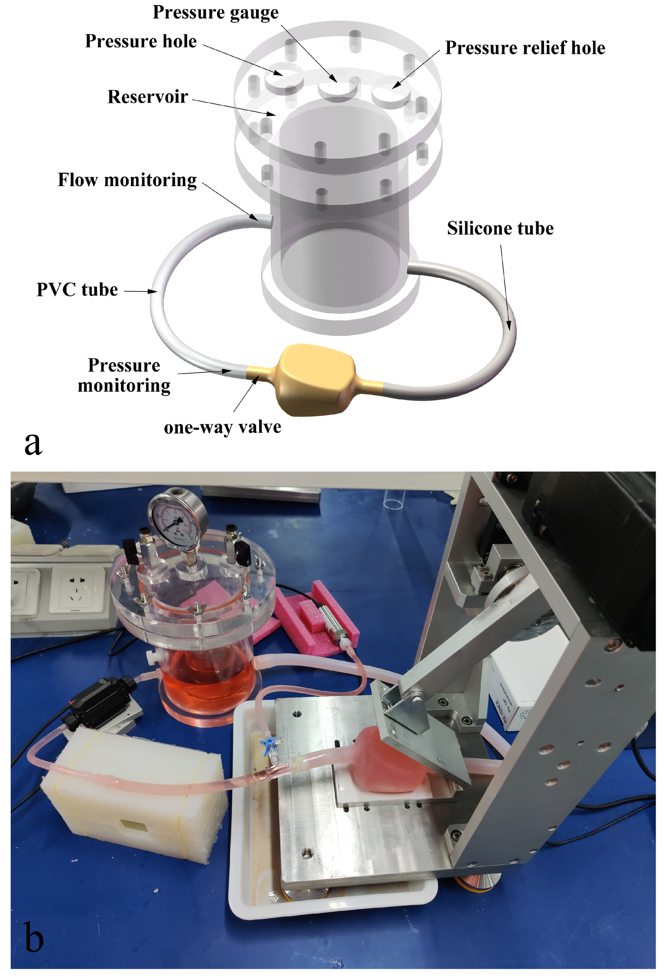
2.1. Design of the Soft-Elastic Pulsation Pump (SEPP)

Figure 1a shows the 3D SEPP (The Bread). The pump chamber was nicknamed ‘Bread’ which makes it easier for referring to in the following discussion. The design idea came from the laboratory’s previous works on an angled extrusion device for mimicking the rat stomach for in vitro digestion studies [21,22]. It arrived at the idea of a trapezoidal body with a clamping extrusion angle. Each stroke of the squeezing plate acting on the upper side of the Bread yields a fluid extrusion process. The upper and lower sides of the extrusion contact are flat, while the left and right sides protrude (bulged) outwards (i.e., roundish). The outlet was made to allow flow to converge to an appropriate cylindrical outlet. The inlet is also of a gradual change. They look like a horn that smoothly transits to the cylindrical tubing for external connectivity (Figure 1a,b). These gradual transits were intended for lesser shear.
Flow is qualitatively indicated in Figure 1b, relative to the geometry, driven by squeezing. In terms of the inner Bread size, the height of the cavity at the inlet side is 23 mm, the width is 57 mm, the height of the cavity at the outlet side is 54 mm, the width is 60 mm, and the length of the cavity is 78 mm, respectively. The diameter of the inlet and outlet is 14 mm. The internal volume of the Bread is about 212 cm3. It is about the size of an adult male heart [23]. Of course, here it is only a single-stroke device which is much less complex than that of the heart. Figure 1c–f show the images of the real molds and the final product of the ‘Bread’.
Figure 2 shows the extrusion and the non-return valve setup, which made it feasible, that after each squeezing (each extrusion), the emptied Bread sucks in new fluid. This facilitates a continuous pulsation pumping as desired.

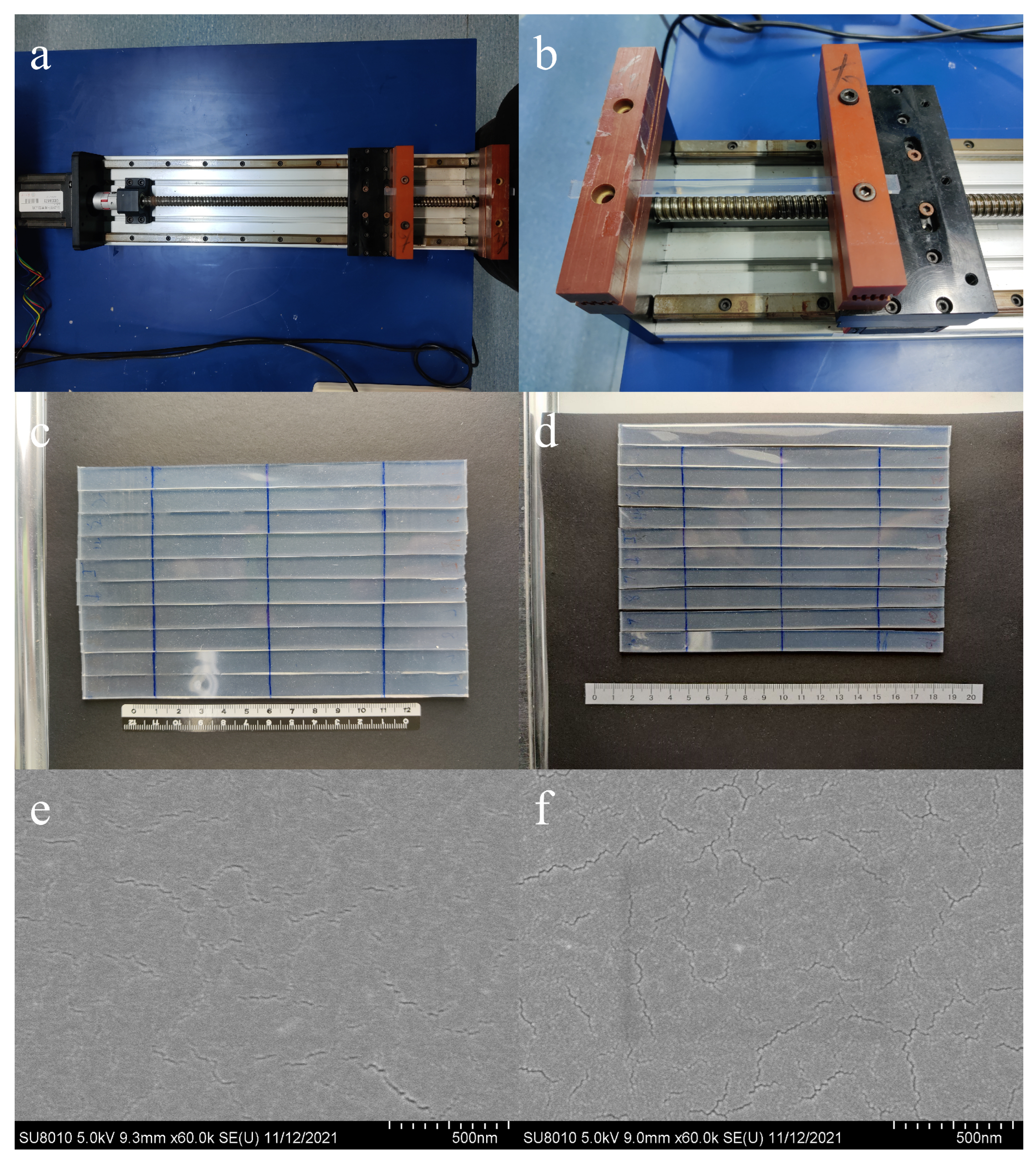
2.2. Producing the SEPP

Referring to Figure 1, the Bread cavity was made using 3D printing technology combined with the lost wax casting method [24]. First, take the CAD file shown in Figure 1a and convert it to a suitable format for 3D printing. UnionTech Lite 600 3D printer (Wenext, Shenzhen, China) was used for printing (i.e., Stereoscopic Light Curing Technology). R4600 photosensitive resin was the material. The inner mold was made first by ‘computationally thickening’ of 3 mm to allow an outer-cavity mold to be printed (Figure 1c). The wall thickness of the Bread VAD was 3 mm as a result. It is noted that the 3D printing technology can only print the hard molds at this stage.
After the above hard molds were made, the soft-elastic molds, i.e., the silicone molds, which have the same geometry and dimensions, were made too. The flexible nature of the silicone material after curing makes it easier to de-mold and detach the completed Bread. The PS6600 type silicone rubber (Shenzhen Yipin Yipin Trading Co., Ltd., Shenzhen, China) was used (Figure 1d). The mold master was made into two halves. Similarly, the outer mold master was made (Figure 1e).
The wax core was necessary for making the Bread inner chamber. Here, an acrylic rod with a diameter of 14 mm was fixed in the inner master mold in advance, and the solid polyethylene glycol (PEG) was placed in an oven and heated at 80 °C. Slowly pouring the melted PEG into the inner mold master, while gently shaking to prevent the air bubbles in the PEG from being adsorbed on the wall of the master mold. Replenishing PEG after 4 h of cooling at room temperature. The PEG wax core was then made.
The PEG solid wax core was then placed into the outer mold master. The gap between the wax core and the silicone outer mold was filled with a medical high-transparency silicone rubber type 3042 (Shenzhen Yipin Yipin Trading Co., Ltd., Shenzhen, China). This formed the Bread’s wall. The silicone material has a Shore hardness of 40 degrees, a tear strength of 11.49 KN/m, a tensile strength of 4.7 MPa and the elongation at break is 220%. The wall was occasionally cut into flat square sections to carry out tensile tests of >10,000 times, the wall material properties did not change.
After filling, a vacuum at 1Pa was applied for 12 h, the molding assembly was placed in an oven set at 50 °C for 48 h. The inner PEG was then removed after heating to above 70 °C. The Bread was detached from the silicone outer mold as well. Then, the Bread alone still needs to be heated in an oven at 100 °C for 12 h until the cavity structure was completely formed.
For the one-way valve installed at the Bread cavity outlet, originated from an idea exercised previously in the same group for making a bionic rat stomach and a bionic stomach model [25], and a modified design was realised. In addition, a custom-made metal mold (contract made by Haocheng Metal Materials Co., Ltd., Shanghai, China) was used. Figure 2 shows the images of the mold and the finished one-way valve.
The one-way valve is a cylindrical passage, and there are two thin layers of 2 mm silicone rubber inside which are integrally formed within the main body (Figure 2c). These two thin layers of silicone rubber are sliced with a thin sharp knife, and the angle between the thin layers of silicone rubber is 30°. This converging angle is conducive to the flow to go through the conduit. The silicone rubber has a Shore hardness of 10 degrees. When the sample blood flow passes through the valve, the gap between the two silicone rubber ‘lips’ can be easily opened. The reverse, however, due to the pressing of liquid on both sides of the protruding lips, the flow cannot go through, realizing the one-way operation.
In view of the deformation of the Bread cavity during the fluid extrusion process, it was necessary to select a material with high strength. The mechanical properties of the silicone rubber type 3042 were found to be suitable. Moreover, Type 3042 retains reasonable transparency when the shore hardness reaches 40 degrees, which was feasible for observing the flow in the experiments.

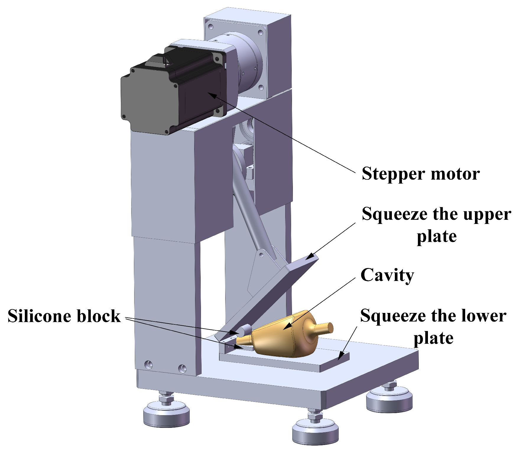
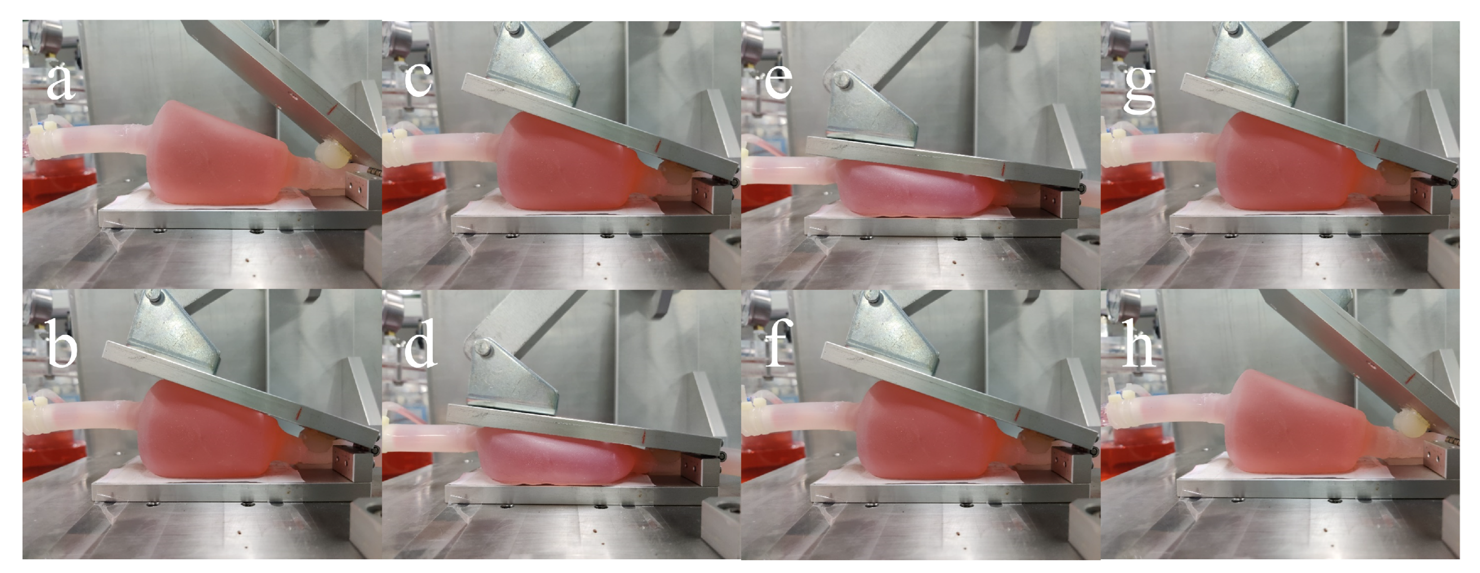
2.3. Actuation of the SEPP

The device was powered with mechanical extrusion driven externally by an electro-mechanical device (Figure 3). A step motor was installed on the electro-mechanical device and was connected to a rotating wheel and with the transmission rod to control the pressing and lifting actions of the metal plate. The upper and lower plates were fixed by hinges, and there was a gap in the middle, allowing for the placement of the inlet tubing of the Bread. Through the operation of a programmable logic controller (PLC), the internal storage and execution of logic operations, sequence control, timing, counting, and other operations were set up to achieve precise control with different synchronizing lengths and speeds. At the entrance of the Bread, a solid silicone rubber rod and a silicone rubber gasket (a stopper) were, respectively fixed. Upon closing the extruder upper plate and lower plate which are metallic, the silicone rod took the role of the check valve of the Bread inlet.
When the upper plate is at the highest point, the silicone rod only just touches the inlet tubing of the Bread. When the upper plate is pressed down until it just touches the Bread top surface, the silicone rod would completely shut the inlet. As such when the upper metal plate press extruded the fluid within the Bread, no fresh fluid can come into the Bread.
When the upper metal plate continued to squeeze down to the lowest level, the silicone rod and the inlet tubing were deformed to the maximum. The Bread was squeezed to extrude the liquid. This process was defined as the Contact Drop Phase (CDP). Before that, the upper plate comes in touch with the upper side of the Bread and it was called the Non-Contact Drop Phase (NCDP). The ‘drop’ referred to the upper metal plate moving from the top position downwards. After each extrusion was completed, the upper metal plate started to rise until it returned to the end of the NCDP. At this time, due to the closure of the inlet and outlet, the Bread cavity remained flat in a deformed state. This period was defined as the Contact Ascending Phase (CAP). The upper metal plate continued to rise to its original position. During the process, the silicone rod gradually released the Bread inlet, and the Bread cavity started to refill to full. This process was defined as the Non-Contact Ascending Phase (NCAP). The one-whole process is demonstrated in Figure 4.

2.4. SEPP Operated in Circulations

Figure 5 shows a laboratory circulation loop consisting of a 3 L reservoir, medical polyvinyl chloride (PVC) tubing, outlet check valve, Bread cavity, and silicone rubber tubings. The reservoir is a customized pressure vessel made of acrylic with a maximum working pressure of 0.2 MPa (gauge pressure). The connections of PVC pipe–PVC pipe and PVC pipe–reservoir were of medical polypropylene (PP) tubings. The joint of the PVC pipe and the one-way valve was installed with a sampling port.
A pressure sensor (SUAY12.6.A1.M2.N1, Nanjing Xuanye Measurement and Control Technology Co., Ltd., Nanjing, China) was installed at the outlet check valve position, and a clamp-type ultrasonic flow sensor was installed at the reservoir inlet. The reservoir was composed of a cylindrical tank and a cap.
An elastic rubber ring is used to seal between the tank and the cap. A vent hole and a pressure gauge are installed on the cap. The air compressor boosted the pressure of the circuit through another opening on the cap to cope with the post-load due to the pulsation. The varying pressure was monitored through the pressure gauge. When the critical pressure of 0.2 MPa was reached, the vent automatically deflated to ensure the system’s safety.

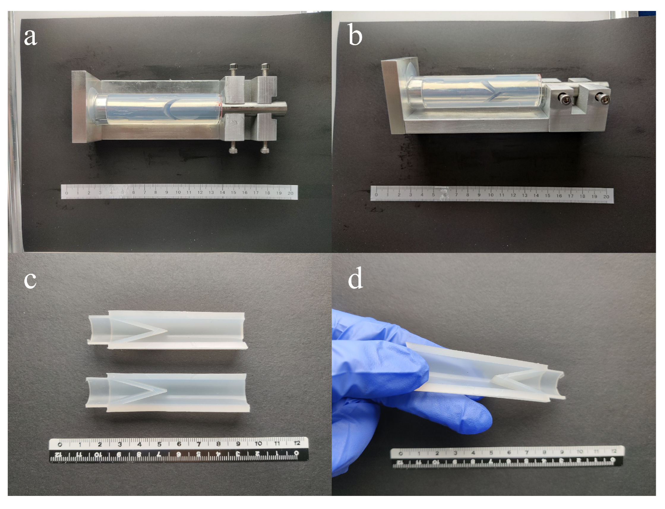
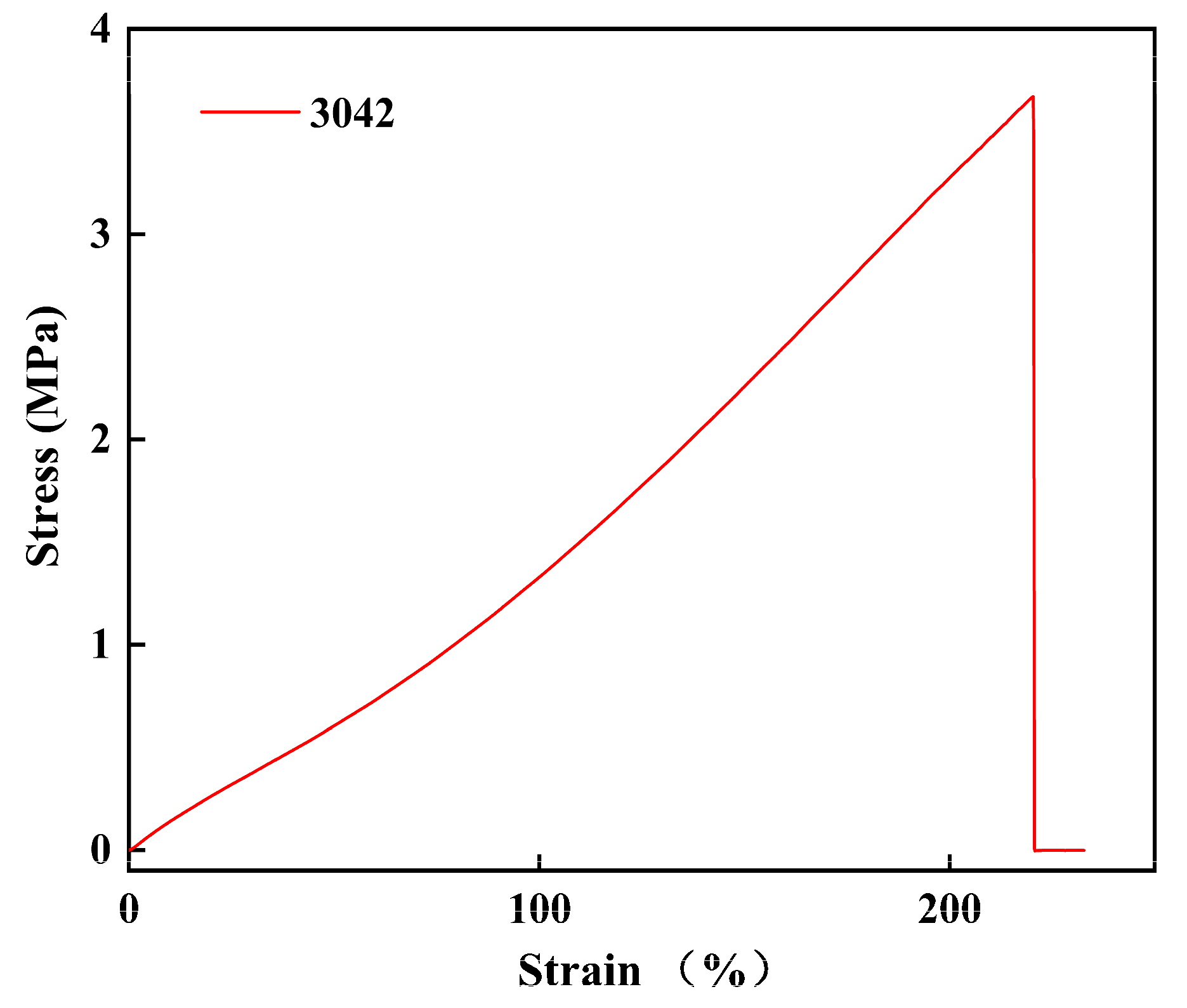
2.5. The Material Properties of the SEPP

It was clear that the durability of the system was of great importance that one has to address when considering a real application in future. A custom-made stretching machine (see Figure 6) in our laboratory was used to perform continuously 10,000 stretches on the 3042 silicone rubber strips made the same way as the Bread. The thickness of the silicone rubber strip was 2 mm, when the initial length was 100 mm, and the length was stretched to was 120 mm (i.e., the elongation was 20%).
The relative changes in the surface morphology of the samples were analyzed by Scanning Electron Microscopy (SEM). The field emission scanning electron microscope used was HITACHI SU-8010 (HITACHI, Tokyo, Japan), equipped with an electron gun, operating in the voltage range of 3–30 kV in high vacuum mode. A 10-nm-thick gold film was coated on the surface of the silicone rubber samples by sputtering to avoid artifacts caused by surface charging.

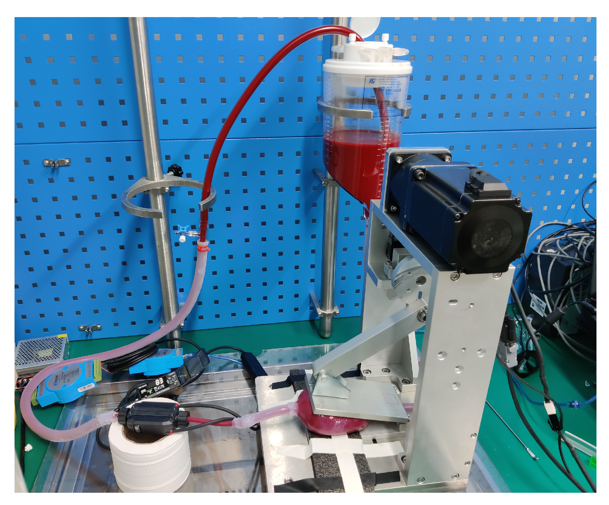
2.6. Initial Test on Real Blood

The circulation system was taken to the well-established animal research center of Tianjin TEDA hospital which has the permit to collect pig blood to carry out in vitro tests. To test the damage to the blood under the continuous operation of the device, we performed a low-pressure in vitro hemolysis test with an afterload of 40 mmHg (Figure 7). The experimental blood of 0.8 L was collected from healthy and quarantine-qualified experimental pigs. The experimental animals were kept in isolation and fasted for 12 h before the blood collection. During blood collection, the blood in the bag was slowly shaken to keep mixed. A disposable medical blood collection bag containing citrate-phosphate-glucose-adenine anticoagulant was used. Each bag of 200 mL and a total of four bags were obtained. Since the circuit was open to the atmosphere, a disposable blood reservoir hemofilter was used as the blood reservoir (different from the laboratory setup mentioned in the methods section due to practicality issues at the time). Before the test the SEPP and the circuit were rinsed with phosphate-buffered solution (PBS), the experimental blood collected was slowly filled into the reservoir, and 1 mL (3000 IU) of heparin sodium was injected at the same time.

3. Results and Discussion

3.1. On the SEPP Material

There was no obvious irreversible deformation of the silicone rubber strip seen after the tests (Figure 6c,d). From the SEM images (Figure 6e,f), there was no obvious change after stretching 10,000 times under the observation range of 500 nm, indicating that the durability of 3042 silicone rubber was sufficient for the research purpose. Figure 8 shows the stress–strain curve of the 3042 silicone rubber sample tested with a universal mechanical testing machine, and dumbbell-shaped specimens made according to ASTM-D412 [26]. The thickness was 2 ± 0.2 mm, the tensile strength was 4.7 MPa, and the elongation at the breaking point was 220%. This met the deformation requirements for the current extrusion process.
In fact, the Bread withstood 30,000 times of continuous operation of pulsation pumping without dysfunction. A microscopic inspection found no visible changes after long-term extrusion.

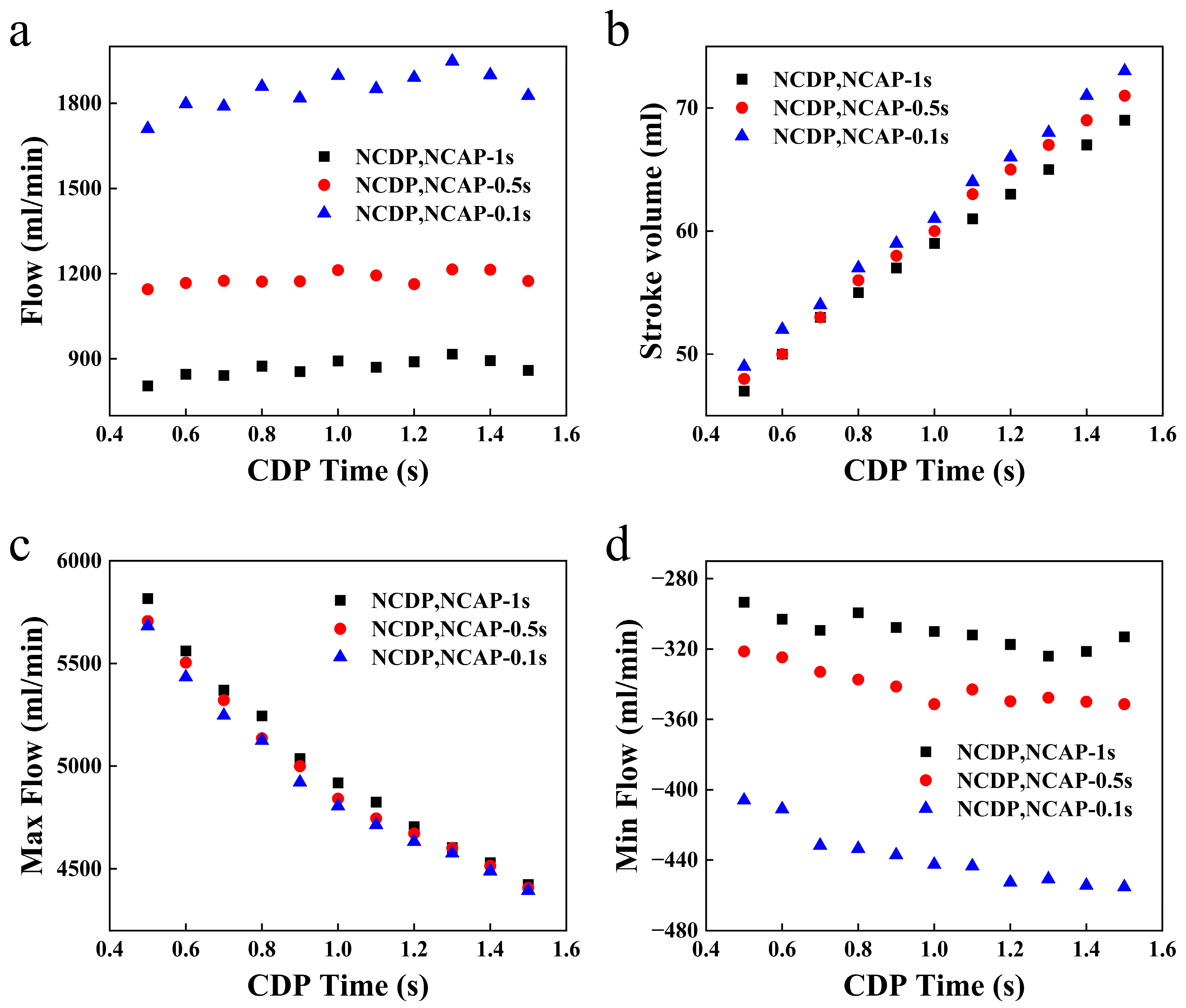
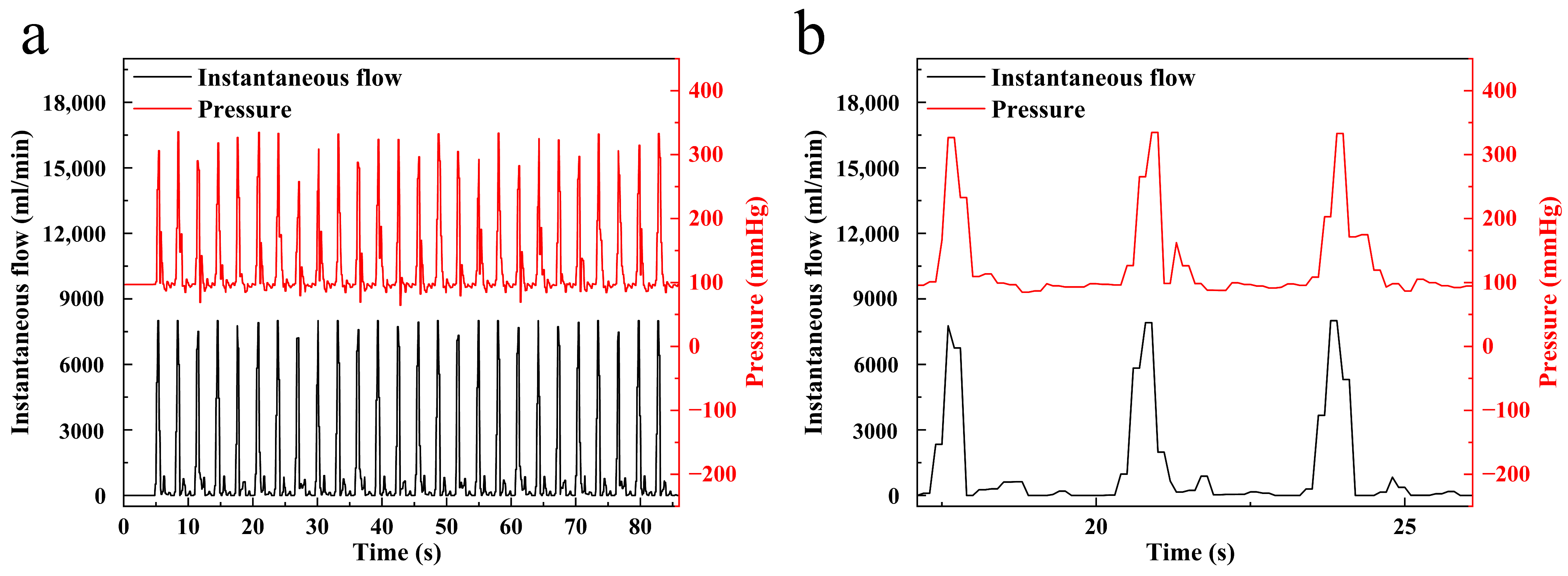
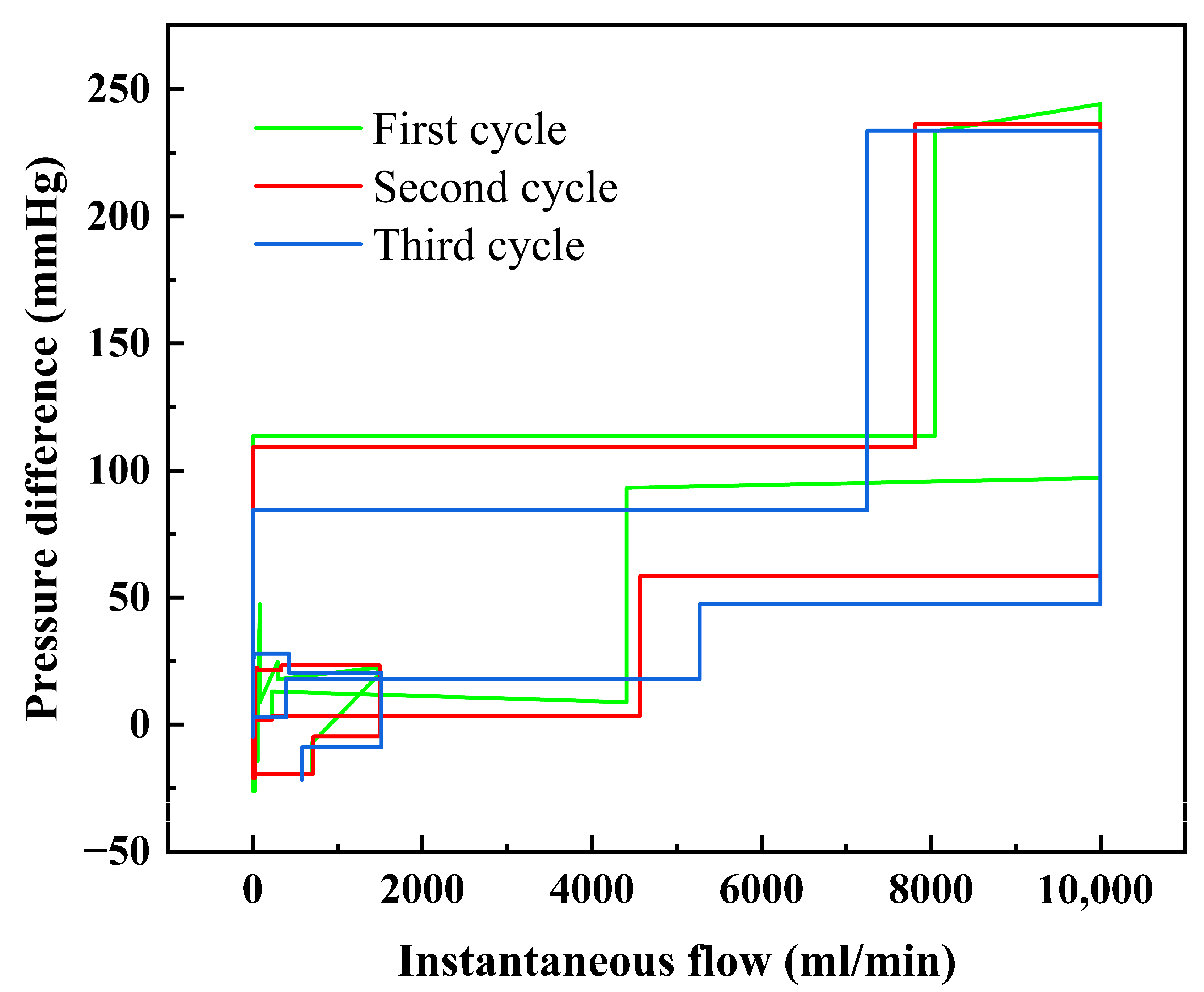
3.2. Pumping Performance

Figure 9 shows the effect of changing the CDP time by changing the CDP speed on the volumetric flow, instantaneous peak flow, instantaneous valley flow, and stroke volume of the SEPP under a physiological pressure of 100 mm Hg. NCDP, NCAP, and CAP operation times were fixed at 1 s, 1 s, and 0.5 s, respectively. With the increase in the CDP time, the stroke volume showed a stable growing trend. It was because the energy of the upper metal plate pressing the Bread could not be converted instantly into the power for driving the liquid. One part of the energy must be absorbed by the Bread due to the nature of the soft-elastic material of the Bread wall in the way seen previously for a soft-elastic reactor (SER) in the same laboratory [27,28,29,30].
As such, there was a delay in initiating the liquid flow after the initial contact of the upper metal plate to the top of the Bread. If the CDP time was short, the Bread was only deformed but not actually moving the liquid. Increasing the CDP time deepened this process so that the Bread (the SEPP) worked.
The reduction of NCDP and NCAP time was realized by increasing the extrusion speed, this resulted in a higher speed at the end of the NCD and led to the increase of kinetic energy acting on the Bread, so there was a small increase in the stroke volume. For volumetric flow, when the stroke volume increased, the single extrusion cycle was extended, and the number of extrusions achieved per minute decreased. There was a tendency for the volumetric flow to fluctuate. The reduction of NCDP and NCAP time greatly shortened the extrusion cycle. For example, when the NCDP and NCAP times were set at 0.1 s and 1 s, respectively, the CAP time was 0.5 s and the CDP time was set to 0.5 s, a complete cycle, i.e., extrusion and recovery, were 1.2 s and 3 s, correspondingly.
This directly affected the volumetric flow rate, resulting in 1711 mL/min to 805 mL/min, correspondingly. The instantaneous peak flow was directly related to the speed of the upper metal plate during the CDP. The greater the speed of the moving of the upper metal plate, the higher the kinetic energy obtained by the Bread or the SEPP, the greater the instantaneous peak flow, and the shorter CDP time. With enlarging CDP time, the influence of NCDP and NCAP time that changed the instantaneous peak flow was weakened. When the CDP time was 1.5 s, the three instantaneous peak flow values were almost equal. For the instantaneous valley flow, some small negative values were recorded, indicating that there was a small amount of flow reversal, which might be caused by the sharp increase in the pressure in the loop in the later stage of the CAP. This might be much greater than the pressure in the Bread or the SEPP. In general, the instantaneous valley flow was not affected much by the CDP time. The reduction of the NCDP and NCAP time corresponded to a small increase in the instantaneous valley flow.
Figure 10 shows the instantaneous flow rate and outlet pressure measured of the SEPP at 100 mmHg when the NCDP and the NCAP time were both 1 s; the CDP and the CAP time were both 0.5 s. It is noted that the afterload refers to the study of Cohrs et al. [17]. When the afterload was 100 mmHg, the instantaneous flow and the pressure had a similar wavy pattern. During NCDP, the upper metal plate did not touch the Bread top, and the instantaneous flow and outlet pressure were at their initial values.
There was a constant plateau. After entering NCAP, small fluctuations of the instantaneous flowrate and the outlet pressure were observed. This was caused by the movement of the Bread upon pressing and releasing by the upper metal plate. When the metal upper metal plate left the Bread and entered NCAP, the Bread rebounded. Because of the elasticity of silicone rubber, pressure fluctuation would occur again. However, the chamber and check valve were flexible and had a certain degree of compliance, pressure feedback was faster than the flow feedback. Chong et al. showed that a pump generating the waveforms that conform to human physiology is considered to be more suitable for use in experimental studies of vascular blood flow [31].
Figure 11 shows the relationship between the measured instantaneous flow rate and the pressure difference between the inlet and the outlet of the Bread under the same conditions, showing the cycling signals of three cycles. It was obvious that the pressure signal was ahead of the flow signal. Before starting the SEPP, both pressure difference and flow were 0. After the equipment started to operate, it entered CDP through NCDP, at that moment, the pressure difference increased sharply first, then the instantaneous flow signal would appear. When the instantaneous flow reached the maximum, the flow difference signal decreased first, and the instantaneous flow decreased accordingly.

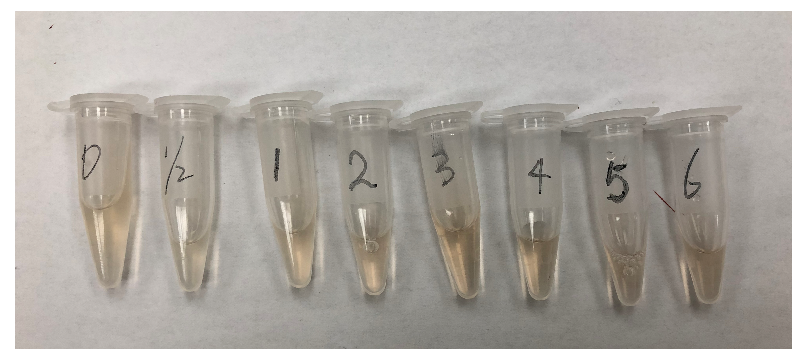
3.3. Real Blood Test

Employing the protocols described in Section 2.6, after 5 min of initial circulation with the blood, ensure that the blood is properly looped. The initial blood samples of 2 mL and 1 mL were drawn, respectively. The 2 mL samples were centrifuged to detect free hemoglobin (FHB) and the 1 mL samples were used for the blood routine test. Continuous circulation for 6 h in the SEPP system, sampling at 0.5 h, 1 h, 2 h, 3 h, 4 h, 5 h, and 6 h from the start, respectively. It was evident that the color of the supernatant drawn after centrifugation at 3500 rpm for 5 min had no visible difference (Figure 12). The test data are shown in Figure 12, where FHB refers to the concentrplasma-freeasma free hemoglobin. The standard hemolysis index was calculated using the standard method ASTM F 1841 [32]:
N . I . H = Δ F r e e   H b × V × 100 H c t 100 × 100 Q × T ,
where N.I.H is the standard hemolysis index, ∆Free HbFHB) is the increase in the concentration of the plasma free hemoglobin (g/L) from the beginning of circulation, V is the circulating blood volume (L), Hct is the hematocrit (%), Q is the flow rate (L/min), and T is the time from the start of the circulation.
Figure 13 shows the analytical results of a 6 h in vitro test on blood circulation. For the first 60 min, a fast increase in ΔFHB was observed. This was probably due to incomplete cleaning of the inside of the circulation loop or certain aspects of biocompatibility of the rial were not the most ideal. Considering the hemolysis caused by exposure of the blood to air, the increase in ΔFHB here was not high. Roberts et al. tested Impella CP for in vitro hemolysis within 3 h [33]. In their tests, at 180 min, ΔFHB was already 40 mg/L, which was higher than the 37 mg/L at the 180 min mark in the current study. Svitek et al. performed a 6 h in vitro hemolysis test on the Tandem Heart Pediatric Pump and the BP-50 Pediatric Pump. At 6 h, their ΔFHB was 84 mg/L for Tandem Heart and 101 mg/L for BP-50, respectively [34]. In the current, N.I.H.s were lower values and a benign decreasing trend.
The initial detected value of N.I.H was 0.0189 g/100 L. Considering that the Q value was 1 L/min, which was lower than the test standard [30], the initial N.I.H value was high. There was, however, no significant change in the hematocrits throughout the experiment. During the process, it was observed that there was thrombosis in the local pipe in the circulation circuit, which was located in a hidden dead corner and was not easy to clean, which might explain the sudden increase in ΔFHB at the beginning of the experiment.

3.4. A Remark

It has been shown that a soft-elastic pulsation pump (SEPP) can be made, such as a soft-elastic reactor (SER) previously developed in the same team over the past decade. The mechanism for powering the fluid flow is simple, i.e., squeezing/extruding. The pulse generated in each extrusion, if used for the purpose of a VAD, may make better sense than that used with a rotational device which generates no pulse. Once scaled up, it may make its way into the field of VAD. It is interesting to note that the current device may be duplicated working in parallel making a larger throughput. Since it is soft and elastic, the absorption of the energy from the external squeezing and the internal deformation without sharp edges/corners seem to moderate the flowing condition to minimize high shear. Silicone material is indeed excellent and versatile, which has a good range to choose from for making different parts of the SEPP system. The durability of the SEPP is also promising at least in the current way of making it which had survived over 30,000 extrusions without noticeable issues. To prove the validity of the device for pumping real blood with little damage, much longer period of operation needs to be investigated, which is beyond the current scope of the work.

4. Conclusions

In this paper, a soft elastic pulsation pump (SEPP) was designed and made many times over for testing towards potential medical applications. Much of the technical details have been recorded. The space inside the pump (the Bread) has no sharp edges or corners to avoid high shear. High shear is known to cause damage to blood. The SEPP is powered by squeezing its wall. Interesting flow characteristics were observed. A preliminary hemolysis test showed a very mild hemolysis which may serve as a proof of concept. If optimized, the current SEPP may be tested towards a VAD or a heart failure model. Furthermore, the current approach is scalable in that the flow rate of the device can be increased to meet the normal physiological demands of 5 L/min. This may be achieved through a series of the same device in parallel. Improvements in biocompatibility may be made further. Alternatively, a single but larger SEPP may be constructed to be investigated in the near future.

Author Contributions

H.G.: Laboratory testing, mechanical design, material selection, processing, and manuscript preparation; Y.X.: Material selection and processing, molding design; Y.Z.: Conceptualization, supervision, and manuscript preparation; X.D.C.: Conceptualization, mechanical design, material selection and processing, lab testing, supervision, manuscript preparation, and manuscript finalization. All authors have read and agreed to the published version of the manuscript.

Funding

The project was funded through a sub-project contracted to Xiao Dong Pro-health Instrumentation (Suzhou) Ltd. for conceptual design and fabrication. The main project funding was from the Tsinghua University Initiative Scientific Research Program (Nos. 20182000306 and 20229990132).

Data Availability Statement

The data presented in this study are available on request from the corresponding author. Some of the data may be not publicly available due to conditions of funding.

Conflicts of Interest

The authors declare no conflict of interest.

References

  1. Koprivanac, M.; Kelava, M.; Soltesz, E.; Smedira, N.; Kapadia, S.; Brzezinski, A.; Alansari, S.; Moazami, N. Advances in temporary mechanical support for treatment of cardiogenic shock. Expert Rev. Med. Devices 2015, 12, 689–702. [Google Scholar] [CrossRef] [PubMed]
  2. Schumer, E.M.; Black, M.C.; Monreal, G.; Slaughter, M.S. Left ventricular assist devices: Current controversies and future directions. Eur. Heart J. 2016, 37, 3434–3439. [Google Scholar] [CrossRef] [PubMed]
  3. Prinzing, A.; Herold, U.; Berkefeld, A.; Krane, M.; Lange, R.; Voss, B. Left ventricular assist devices-current state and perspectives. J. Thorac. Dis. 2016, 8, E660–E666. [Google Scholar] [CrossRef] [PubMed]
  4. Thunberg, C.A.; Gaitan, B.D.; Arabia, F.A.; Cole, D.J.; Grigore, A.M. Ventricular assist devices today and tomorrow. J. Cardiothorac. Vasc. Anesth. 2010, 24, 656–680. [Google Scholar] [CrossRef]
  5. Badiye, A.P.; Hernandez, G.A.; Novoa, I.; Chaparro, S.V. Incidence of Hemolysis in Patients with Cardiogenic Shock Treated with Impella Percutaneous Left Ventricular Assist Device. ASAIO J. 2016, 62, 11–14. [Google Scholar] [CrossRef]
  6. Katz, J.N.; Jensen, B.C.; Chang, P.P.; Myers, S.L.; Pagani, F.D.; Kirklin, J.K. A multicenter analysis of clinical hemolysis in patients supported with durable, long-term left ventricular assist device therapy. J. Heart Lung Transpl. 2015, 34, 701–709. [Google Scholar] [CrossRef]
  7. Li, H.; Gou, Z.; Huang, F.; Ruan, X.D.; Qian, W.W.; Fu, X. Evaluation of the hemolysis and fluid dynamics of a ventricular assist device under the pulsatile flow condition. J. Hydrodyn. 2018, 31, 965–975. [Google Scholar] [CrossRef]
  8. Papanastasiou, C.A.; Kyriakoulis, K.G.; Theochari, C.A.; Kokkinidis, D.G.; Karamitsos, T.D.; Palaiodimos, L. Comprehensive review of hemolysis in ventricular assist devices. World J. Cardiol. 2020, 12, 334–341. [Google Scholar] [CrossRef]
  9. Ravichandran, A.K.; Parker, J.; Novak, E.; Joseph, S.M.; Schilling, J.D.; Ewald, G.A.; Silvestry, S. Hemolysis in left ventricular assist device: A retrospective analysis of outcomes. J. Heart Lung Transplant. 2014, 33, 44–50. [Google Scholar] [CrossRef]
  10. Copeland, H.; Berumen, J.; Smith, R.G.; Copeland, J.G. The Artificial Heart. In Textbook of Organ Transplantation; John Wiley & Sons: Hoboken, NJ, USA, 2014; pp. 563–567. [Google Scholar]
  11. Copeland, J.; Copeland, H. Pulsatile Mechanical Circulation, Physiology, and Pump Technology. In Mechanical Support for Heart Failure; Springer: Berlin/Heidelberg, Germany, 2020; pp. 231–252. [Google Scholar]
  12. Sunagawa, G.; Koprivanac, M.; Karimov, J.H.; Moazami, N.; Fukamachi, K. Is a pulse absolutely necessary during cardiopulmonary bypass? Expert Rev. Med. Devices 2017, 14, 27–35. [Google Scholar] [CrossRef]
  13. Yeh, Y.C.; Yamada, N.; Watanabe, Y.; Shiblee, M.N.I.; Ogawa, J.; Khosla, A.; Kawakami, M.; Akamatsu, T.; Furukawa, H. 3D printing of soft-matter mono pump in infant ventricular assist device (VAD) for blood pumping. ECS Trans. 2020, 98, 31. [Google Scholar] [CrossRef]
  14. Miller, J.R.; Singh, G.K.; Woodard, P.K.; Eghtesady, P.; Anwar, S. 3D printing for preoperative planning and surgical simulation of ventricular assist device implantation in a failing systemic right ventricle. J. Cardiovasc. Comput. Tomogr. 2020, 14, e172–e174. [Google Scholar] [CrossRef] [PubMed]
  15. Thaker, R.; Araujo-Gutierrez, R.; Marcos-Abdala, H.G.; Agrawal, T.; Fida, N.; Kassi, M. Innovative Modeling Techniques and 3D Printing in Patients with Left Ventricular Assist Devices: A Bridge from Bench to Clinical Practice. J. Clin. Med. 2019, 8, 635. [Google Scholar] [CrossRef]
  16. Vukicevic, M.; Mosadegh, B.; Min, J.K.; Little, S.H. Cardiac 3D Printing and its Future Directions. JACC Cardiovasc. Imaging 2017, 10, 171–184. [Google Scholar] [CrossRef] [PubMed]
  17. Cohrs, N.H.; Petrou, A.; Loepfe, M.; Yliruka, M.; Schumacher, C.M.; Kohll, A.X.; Starck, C.T.; Schmid Daners, M.; Meboldt, M.; Falk, V.; et al. A soft total artificial heart-first concept evaluation on a hybrid mock circulation. Artif. Organs 2017, 41, 948–958. [Google Scholar] [CrossRef] [PubMed]
  18. Guex, L.G.; Jones, L.S.; Kohll, A.X.; Walker, R.; Meboldt, M.; Falk, V.; Schmid Daners, M.; Stark, W.J. Increased longevity and pumping performance of an injection molded soft total artificial heart. Soft Robot. 2021, 8, 588–593. [Google Scholar] [CrossRef] [PubMed]
  19. Mao, Z.; Asai, Y.; Yamanoi, A.; Seki, Y.; Wiranata, A.; Minaminosono, A. Fluidic rolling robot using voltage-driven oscillating liquid. Smart Mater. Struct. 2022, 31, 105006. [Google Scholar] [CrossRef]
  20. Mao, Z.; Asai, Y.; Wiranata, A.; Kong, D.; Man, J. Ececentric actuator driven by stacked electrohydrodynamic pumps. J. Zhejiang Univ. Sci. A (Appl. Phys. Eng.) 2022, 23, 329–334. [Google Scholar] [CrossRef]
  21. Chen, L.; Jayemanne, A.; Chen, X.D. Venturing into in vitro physiological upper GI system focusing on the motility effect provided by a mechanised rat stomach model. Food Dig. 2012, 4, 36–48. [Google Scholar] [CrossRef]
  22. Chen, L.; Wu, X.; Chen, X.D. Comparison between the digestive behaviors of a new in vitro rat soft stomach model with that of the in vivo experimentation on living rats—Motility and morphological influences. J. Food Eng. 2013, 117, 183–192. [Google Scholar] [CrossRef]
  23. Ford, L. Heart size. Circ. Res. 1976, 39, 297–303. [Google Scholar] [CrossRef] [PubMed]
  24. Tourlomousis, F.; Chang, R.C. Dimensional Metrology of Cell-matrix Interactions in 3D Microscale Fibrous Substrates. Procedia CIRP 2017, 65, 32–37. [Google Scholar] [CrossRef]
  25. Chen, L. In Vitro Bionic Rat and Human Stomach: Construction and Preliminary Applications. Ph.D. Thesis, Xiamen University, Xiamen, China, 2013. (In Chinese). [Google Scholar]
  26. Azmi, N.N.; Patar, M.N.A.A.; Noor, S.N.A.M.; Mahmud, J. Testing standards assessment for silicone rubber. In Proceedings of the 2014 International Symposium on Technology Management and Emerging Technologies, Bandung, Indonesia, 27–29 May 2014; pp. 332–336. [Google Scholar]
  27. Liu, M.; Xiao, J.; Chen, X.D. A Soft-Elastic Reactor Inspired by the Animal Upper Digestion Tract. Chem. Eng. Technol. 2018, 41, 1051–1056. [Google Scholar] [CrossRef]
  28. Xiao, J.; Zou, C.; Liu, M.; Zhang, G.; Delaplace, G.; Jeantet, R.; Chen, X.D. Mixing in a soft-elastic reactor (SER) characterized using an RGB based image analysis method. Chem. Eng. Sci. 2018, 181, 272–285. [Google Scholar] [CrossRef]
  29. Delaplace, G.; Gu, Y.; Liu, M.; Jeantet, R.; Xiao, J.; Chen, X.D. Homogenization of liquids inside a new soft elastic reactor: Revealing mixing behavior through dimensional analysis. Chem. Eng. Sci. 2018, 192, 1071–1080. [Google Scholar] [CrossRef]
  30. Delaplace, G.; Liu, M.; Jeantet, R.; Xiao, J.; Chen, X.D. Predicting the mixing time of soft elastic reactors: Physical models and empirical correlations. Ind. Eng. Chem. Res. 2020, 59, 6258–6268. [Google Scholar] [CrossRef]
  31. Chong, A.B.; Sun, Z.H.; van de Velde, L.; Jansen, S.; Versluis, M.; Reijnen, M.; Groot Jebbink, E. A novel roller pump for physiological flow. Artif. Organs 2020, 44, 818–826. [Google Scholar] [CrossRef]
  32. ASTM F1841-19e1; Standard Practice for Assessment of Hemolysis in Continuous Flow Blood Pumps. ASTM International: West Conshohocken, PA, USA, 1841.
  33. Roberts, N.; Chandrasekaran, U.; Das, S.; Qi, Z.; Corbett, S. Hemolysis associated with Impella heart pump positioning: In vitro hemolysis testing and computational fluid dynamics modeling. Int. J. Artif. Organs 2020, 43, 710–718. [Google Scholar] [CrossRef]
  34. Svitek, R.G.; Smith, D.E.; Magovern, J.A. In vitro evaluation of the TandemHeart pediatric centrifugal pump. ASAIO J. 2007, 53, 747–753. [Google Scholar] [CrossRef]
Figure 1. The SEPP. (a) Various views of the CAD design; (b) Axial cross-sectional view of the interior of the model showing the liquid flow direction; (c) 3D printed inner and outer molds; (d) The inner mold master; (e) The external mold master; (f) The flexible elastic Bread in a squeezed state.
Processes 11 01581 g001
Figure 2. (a,b) Front view and side view of one-way valve mold (filled with medical silicone rubber with Shore hardness of 10°). (c,d) Sectional diagram of the finished product of the one-way valve.
Processes 11 01581 g002
Figure 3. Schematic diagram of electro-mechanical device which drives the SEPP.
Processes 11 01581 g003
Figure 4. The four stages of an extrusion cycle. (a,b) Non-contact drop phase (NCDP). (c,d) Contact drop phase (CDP). (e,f) Contact ascending phase (CAP). (g,h) Non-contact ascending phase (NCAP).
Processes 11 01581 g004
Figure 5. (a) Schematic diagram of the laboratory circulation loop. (b) Physical setup of the loop.
Processes 11 01581 g005
Figure 6. Tensile tests of the silicone rubber strip. (a,b) Physical drawing of customized stretching machine, which step length and speed can be adjusted. (c) The 3042 silicone rubber strips before stretching. (d) The 3042 silicone rubber strips after stretching (from top to bottom, the first is the control). (e) The SEM image of the surface of the 3042 silicone rubber strips before stretching. (f) The SEM image of the surface of the 3042 silicone rubber strip after continuously stretching for 10,000 times.
Processes 11 01581 g006
Figure 7. In vitro hemolysis testing: The circulation test is in progress, and the extrusion plate is extruding the Bread.
Processes 11 01581 g007
Figure 8. A typical stress–strain curve of the 3042 silicone rubber samples.
Processes 11 01581 g008
Figure 9. The effect of the CDP time on the flow. (a) The stroke volume was positively correlated with the CDP time. (b) The volumetric flow fluctuated somewhat with increasing CDP time. (c) The prolonging of the CDP time is shown to be beneficial for reducing the instantaneous peak flow, thus reducing the maximum shear stress. (d) The instantaneous valley flow can be negative, indicating that there is a small amount of flow reversal, which is not greatly affected by the CDP time.
Processes 11 01581 g009
Figure 10. Typical instantaneous flow and the outlet pressure measured on the SEPP afterload at 100 mmHg. (a) Example over 90s of running; (b) The same example but zooming in to look at more details of the peaks.
Processes 11 01581 g010
Figure 11. The relationship between the instantaneous flowrate and the pressure difference between the inlet and outlet of the SEPP was measured for the afterload of the 100 mmHg.
Processes 11 01581 g011
Figure 12. In vitro hemolysis assaying. The supernatants obtained by centrifugation after sampling was completed at 0, 0.5, 1, 2, 3, 4, 5, and 6 h of operating SEPP system on real blood.
Processes 11 01581 g012
Figure 13. Relationship of N.I.H and ΔFHB against time in the circulation test (the in vitro hemolysis test) up to 6 h.
Processes 11 01581 g013
Disclaimer/Publisher’s Note: The statements, opinions and data contained in all publications are solely those of the individual author(s) and contributor(s) and not of MDPI and/or the editor(s). MDPI and/or the editor(s) disclaim responsibility for any injury to people or property resulting from any ideas, methods, instructions or products referred to in the content.

