
Evanescent-Field Excited Surface Plasmon-Enhanced U-Bent Fiber Probes Coated with Au and ZnO Nanoparticles for Humidity Detection
 and
and
Abstract
:1. Introduction
2. Principle of Operation of Evanescent Wave Sensor
3. Materials and Methods
3.1. U-Bent Fiber Fabrication
3.2. Nanoparticle Coating Using the Pulsed-Laser Ablation in Liquid (PLAL) Method
3.3. Thin Film Coating Using DC Magnetron Sputtering
3.4. Test Setup
4. Results and Discussion
5. Conclusions and Perspectives
Author Contributions
Funding
Data Availability Statement
Acknowledgments
Conflicts of Interest
References
- Yang, W.; Marr, L.C. Mechanisms by Which Ambient Humidity May Affect Viruses in Aerosols. Appl. Environ. Microbiol. 2012, 78, 6781–6788. [Google Scholar] [CrossRef] [PubMed] [Green Version]
- Peinado, A.; Hammond, J.; Scott, A. Development, validation and transfer of a Near Infrared method to determine in-line the end point of a fluidised drying process for commercial production batches of an approved oral solid dose pharmaceutical product. J. Pharm. Biomed. Anal. 2011, 54, 13–20. [Google Scholar] [CrossRef] [PubMed]
- Arimi, J.; Duggan, E.; O’Sullivan, M.; Lyng, J.; O’Riordan, E. Effect of moisture content and water mobility on microwave expansion of imitation cheese. Food Chem. 2010, 121, 509–516. [Google Scholar] [CrossRef]
- Dijkink, B.H.; Tomassen, M.M.; Willemsen, J.H.; van Doorn, W.G. Humidity control during bell pepper storage, using a hollow fiber membrane contactor system. Postharvest Biol. Technol. 2004, 32, 311–320. [Google Scholar] [CrossRef]
- Sberveglieri, G.; Rinchetti, G.; Groppelli, S.; Faglia, G. Capacitive humidity sensor with controlled performances, based on porous Al2O3 thin film growm on SiO2-Si substrate. Sens. Actuators B Chem. 1994, 19, 551–553. [Google Scholar] [CrossRef]
- Anchisini, R.; Faglia, G.; Gallazzi, M.; Sberveglieri, G.; Zerbi, G. Polyphosphazene membrane as a very sensitive resistive and capacitive humidity sensor. Sens. Actuators B Chem. 1996, 35, 99–102. [Google Scholar] [CrossRef]
- Ali, S.; Jameel, M.A.; Harrison, C.J.; Gupta, A.; Shafiei, M.; Langford, S.J. Nanoporous naphthalene diimide surface enhances humidity and ammonia sensing at room temperature. Sens. Actuators B Chem. 2021, 351, 130972. [Google Scholar] [CrossRef]
- Ali, S.; Jameel, M.A.; Harrison, C.J.; Gupta, A.; Evans, R.A.; Shafiei, M.; Langford, S.J. Enhanced Capacitive Humidity Sensing Performance at Room Temperature via Hydrogen Bonding of Cyanopyridone-Based Oligothiophene Donor. Chemosensors 2021, 9, 320. [Google Scholar] [CrossRef]
- Farahani, H.; Wagiran, R.; Hamidon, M.N. Humidity Sensors Principle, Mechanism, and Fabrication Technologies: A Comprehensive Review. Sensors 2014, 14, 7881–7939. [Google Scholar] [CrossRef] [Green Version]
- Mogera, U.; Sagade, A.A.; George, S.J.; Kulkarni, G.U. Ultrafast response humidity sensor using supramolecular nanofibre and its application in monitoring breath humidity and flow. Sci. Rep. 2014, 4, 4103. [Google Scholar] [CrossRef] [Green Version]
- Borini, S.; White, R.; Wei, D.; Astley, M.; Haque, S.; Spigone, E.; Harris, N.; Kivioja, J.; Ryhänen, T. Ultrafast Graphene Oxide Humidity Sensors. ACS Nano 2013, 7, 11166–11173. [Google Scholar] [CrossRef] [PubMed]
- Rao, X.; Zhao, L.; Xu, L.; Wang, Y.; Liu, K.; Wang, Y.; Chen, G.Y.; Liu, T.; Wang, Y. Review of Optical Humidity Sensors. Sensors 2021, 21, 8049. [Google Scholar] [CrossRef] [PubMed]
- Alwis, L.; Sun, T.; Grattan, K.T.V. Optical fibre-based sensor technology for humidity and moisture measurement: Review of recent progress. Measurement 2013, 46, 4052–4074. [Google Scholar] [CrossRef]
- Sikarwar, S.; Yadav, B.C. Opto-electronic humidity sensor: A review. Sens. Actuators A Phys. 2015, 233, 54–70. [Google Scholar] [CrossRef]
- Estella, J.; de Vicente, P.; Echeverría, J.C.; Garrido, J.J. A fibre-optic humidity sensor based on a porous silica xerogel film as the sensing element. Sens. Actuators B Chem. 2010, 149, 122–128. [Google Scholar] [CrossRef]
- Wang, B.; Zhang, F.; Pang, F.; Wang, T. An optical fiber humidity sensor based on optical absorption. Opt. Sens. Biophotonics 2011, vol. 8311, 83112A. [Google Scholar] [CrossRef]
- Kronenberg, P.; Rastogi, P.K.; Giaccari, P.; Limberger, H.G. Relative humidity sensor with optical fiber Bragg gratings. Opt. Lett. 2002, 27, 1385–1387. [Google Scholar] [CrossRef]
- Berruti, G.; Consales, M.; Giordano, M.; Sansone, L.; Petagna, P.; Buontempo, S.; Breglio, G.; Cusano, A. Radiation hard humidity sensors for high energy physics applications using polyimide-coated fiber Bragg gratings sensors. Sens. Actuators B Chem. 2013, 177, 94–102. [Google Scholar] [CrossRef]
- Yeo, T.; Sun, T.; Grattan, K.; Parry, D.; Lade, R.; Powell, B. Polymer-coated fiber Bragg grating for relative humidity sensing. IEEE Sens. J. 2005, 5, 1082–1089. [Google Scholar] [CrossRef]
- Chen, L.; Li, T.; Chan, C.; Menon, R.; Balamurali, P.; Shaillender, M.; Neu, B.; Ang, X.; Zu, P.; Wong, W.; et al. Chitosan based fiber-optic Fabry–Perot humidity sensor. Sens. Actuators B Chem. 2012, 169, 167–172. [Google Scholar] [CrossRef]
- Khijwania, S.K.; Srinivasan, K.L.; Singh, J.P. An evanescent-wave optical fiber relative humidity sensor with enhanced sensitivity. Sens. Actuators B Chem. 2005, 104, 217–222. [Google Scholar] [CrossRef]
- Matias, I.R.; Arregui, F.J.; Corres, J.M.; Bravo, J. Evanescent Field Fiber-Optic Sensors for Humidity Monitoring Based on Nanocoatings. IEEE Sens. J. 2006, 7, 89–95. [Google Scholar] [CrossRef]
- Satija, J.; Punjabi, N.; Sai, V.V.R.; Mukherji, S. Optimal Design for U-bent Fiber-optic LSPR Sensor Probes. Plasmonics 2014, 9, 251–260. [Google Scholar] [CrossRef]
- Ramakrishna, B.; Sai, V. Evanescent wave absorbance based U-bent fiber probe for immunobiosensor with gold nanoparticle labels. Sens. Actuators B Chem. 2016, 226, 184–190. [Google Scholar] [CrossRef]
- Zhang, C.; Li, Z.; Jiang, S.Z.; Li, C.H.; Xu, S.C.; Yu, J.; Wang, M.H.; Liu, A.H.; Man, B.Y. U-bent fiber optic SPR sensor based on graphene/AgNPs. Sens. Actuators B Chem. 2017, 251, 127–133. [Google Scholar] [CrossRef]
- Takagi, K.; Sasaki, H.; Seki, A.; Watanabe, K. Surface plasmon resonances of a curved hetero-core optical fiber sensor. Sens. Actuators A Phys. 2010, 161, 1–5. [Google Scholar] [CrossRef]
- Rivero, P.J.; Urrutia, A.; Goicoechea, J.; Arregui, F. Optical fiber humidity sensors based on Localized Surface Plasmon Resonance (LSPR) and Lossy-mode resonance (LMR) in overlays loaded with silver nanoparticles. Sens. Actuators B Chem. 2012, 173, 244–249. [Google Scholar] [CrossRef]
- Lin, J.; Tanada, H.; Odawara, K.; Hiragino, Y.; Fujita, Y. Localized Surface Plasmon Effect for ZnO Nanoparticles Based Devices. JSAP-OSA Joint Symposia, Washington, DC, USA; 2015. Available online: https://www.osapublishing.org/abstract.cfm?uri=JSAP-2015-13a_2C_4 (accessed on 1 May 2021).
- Mei, G.S.; Menon, P.S.; Hegde, G. ZnO for performance enhancement of surface plasmon resonance biosensor: A review. Mater. Res. Express 2020, 7, 012003. [Google Scholar] [CrossRef]
- Zhao, Y.; Peng, Y.; Chen, M.-Q.; Xia, F.; Tong, R.-J. U-shaped microfiber coupler coated with polyvinyl alcohol film for highly sensitive humidity detection. Sens. Actuators A Phys. 2019, 285, 628–636. [Google Scholar] [CrossRef]
- Zhao, Z.; Duan, Y. A low cost fiber-optic humidity sensor based on silica sol–gel film. Sens. Actuators B Chem. 2011, 160, 1340–1345. [Google Scholar] [CrossRef]
- Mathew, J.; Semenova, Y.; Farrell, G. A fiber bend based humidity sensor with a wide linear range and fast measurement speed. Sens. Actuators A Phys. 2012, 174, 47–51. [Google Scholar] [CrossRef]
- Yadav, B.C.; Shukla, R.K.; Bali, L.M. Sol-gel processed TiO2 films on U-shaped glass-rods as optical humidity sensor. Indian J. Pure Appl. Phys 2005, 43, 51–55. [Google Scholar]
- Shukla, S.; Parashar, G.; Mishra, A.; Misra, P.; Yadav, B.; Bali, L.; Dubey, G. Nano-like magnesium oxide films and its significance in optical fiber humidity sensor. Sens. Actuators B Chem. 2004, 98, 5–11. [Google Scholar] [CrossRef]
- Fuke, M.V.; Kanitkar, P.; Kulkarni, M.; Kale, B.; Aiyer, R. Effect of particle size variation of Ag nanoparticles in Polyaniline composite on humidity sensing. Talanta 2010, 81, 320–326. [Google Scholar] [CrossRef] [PubMed]
- Gupta, B.; Ratnanjali. A novel probe for a fiber optic humidity sensor. Sens. Actuators B Chem. 2001, 80, 132–135. [Google Scholar] [CrossRef]
- Vijayan, A.; Fuke, M.; Hawaldar, R.; Kulkarni, M.; Amalnerkar, D.; Aiyer, R. Optical fibre based humidity sensor using Co-polyaniline clad. Sens. Actuators B Chem. 2008, 129, 106–112. [Google Scholar] [CrossRef]
- Zamarreño, C.; Hernaez, M.; Del Villar, I.; Matias, I.; Arregui, F. Tunable humidity sensor based on ITO-coated optical fiber. Sens. Actuators B Chem. 2010, 146, 414–417. [Google Scholar] [CrossRef]
- Paul, D.; Dutta, S.; Saha, D.; Biswas, R. LSPR based Ultra-sensitive low cost U-bent optical fiber for volatile liquid sensing. Sens. Actuators B Chem. 2017, 250, 198–207. [Google Scholar] [CrossRef]
- Gao, S.S.; Qiu, H.W.; Zhang, C.; Jiang, S.Z.; Li, Z.; Liu, X.Y.; Yue, W.W.; Yang, C.; Huo, Y.Y.; Feng, D.J.; et al. Absorbance response of a graphene oxide coated U-bent optical fiber sensor for aqueous ethanol detection. RSC Adv. 2016, 6, 15808–15815. [Google Scholar] [CrossRef]
- Xiong, F.; Sisler, D. Determination of low-level water content in ethanol by fiber-optic evanescent absorption sensor. Opt. Commun. 2010, 283, 1326–1330. [Google Scholar] [CrossRef]
- Fabian, M.; Lewis, E.; Newe, T.; Lochmann, S.; Mueller, I. Investigation of ethanol and methanol water mixtures in the visible wavelength area using fibre-optic evanescent field absorption sensors based on a u-shaped, a coil-shaped and a meander-shaped probe. In Proceedings of the 2008 IEEE Sensors Applications Symposium, SAS-2008—Proceedings, Atlanta, GA, USA, 12–14 February 2008; pp. 79–84. [Google Scholar] [CrossRef]
- Memon, S.F.; Ali, M.M.; Pembroke, J.T.; Chowdhry, B.S.; Lewis, E. Measurement of Ultralow Level Bioethanol Concentration for Production Using Evanescent Wave Based Optical Fiber Sensor. IEEE Trans. Instrum. Meas. 2017, 67, 780–788. [Google Scholar] [CrossRef]
- Cai, H.; Chu, F.; Qu, R. U-shaped plastic optical fiber dissolved oxygen sensor. In Proceedings of the 19th International Conference on Optical Fibre Sensors, Perth, Australia, 15–18 April 2008; Volume 7004, p. 70042B. [Google Scholar] [CrossRef]
- Tri, P.N.; Ouellet-Plamondon, C.; Rtimi, S.; Assadi, A.A.; Nguyen, T.A. Chapter 3—Methods for Synthesis of Hybrid Nanoparticles. In Noble Metal-Metal Oxide Hybrid Nanoparticles; Mohapatra, S., Nguyen, T.A., Nguyen-Tri, P., Eds.; Woodhead Publishing: Sawston, UK, 2019; pp. 51–63. [Google Scholar] [CrossRef]
- Mohammadnezhad, M.; Aïssa, B.; Harnagea, C.; Bentouaf, A.; Haddad, E.; Rosei, F. Photovoltaic properties of hybrid c-Si/ZnO nanorod solar cells. Mater. Adv. 2022, 3, 5911–5921. [Google Scholar] [CrossRef]
- Henni, A.; Harfouche, N.; Karar, A.; Zerrouki, D.; Perrin, F.; Rosei, F. Synthesis of graphene–ZnO nanocomposites by a one-step electrochemical deposition for efficient photocatalytic degradation of organic pollutant. Solid State Sci. 2019, 98, 106039. [Google Scholar] [CrossRef]
- Selloum, D.; Henni, A.; Karar, A.; Tabchouche, A.; Harfouche, N.; Bacha, O.; Tingry, S.; Rosei, F. Effects of Fe concentration on properties of ZnO nanostructures and their application to photocurrent generation. Solid State Sci. 2019, 92, 76–80. [Google Scholar] [CrossRef]
- Papadaki, D.; Mhlongo, G.H.; Motaung, D.E.; Nkosi, S.S.; Panagiotaki, K.; Christaki, E.; Assimakopoulos, M.N.; Papadimitriou, V.C.; Rosei, F.; Kiriakidis, G.; et al. Hierarchically Porous Cu-, Co-, and Mn-Doped Platelet-Like ZnO Nanostructures and Their Photocatalytic Performance for Indoor Air Quality Control. ACS Omega 2019, 4, 16429–16440. [Google Scholar] [CrossRef] [Green Version]
- Selopal, G.S.; Mohammadnezhad, M.; Besteiro, L.V.; Cavuslar, O.; Liu, J.; Zhang, H.; Navarro-Pardo, F.; Liu, G.; Wang, M.; Durmusoglu, E.G.; et al. Synergistic Effect of Plasmonic Gold Nanoparticles Decorated Carbon Nanotubes in Quantum Dots/TiO 2 for Optoelectronic Devices. Adv. Sci. 2020, 7, 2001864. [Google Scholar] [CrossRef]
- Cited, R.; Springs, B.; Esse, R.L. Humidity Control System for Wood Products. U.S. Patent US8748723B1, 10 June 2014. [Google Scholar]
- He, Y.Q.; Liu, S.P.; Kong, L.; Liu, Z.F. A study on the sizes and concentrations of gold nanoparticles by spectra of absorption, resonance Rayleigh scattering and resonance non-linear scattering. Spectrochim. Acta Part A Mol. Biomol. Spectrosc. 2005, 61, 2861–2866. [Google Scholar] [CrossRef]
- Birch, K.P.; Downs, M.J. The results of a comparison between calculated and measured values of the refractive index of air. J. Phys. E Sci. Instrum. 1988, 21, 694–695. [Google Scholar] [CrossRef]
- Uikey, P.; Vishwakarma, K. Review of zinc oxide (ZnO) nanoparticles applications and properties. J. Emerg. Technol. Comput. Sci. Electron. 2016, 21, 239–242. [Google Scholar]
- Ennaceri, H.; Wang, L.; Erfurt, D.; Riedel, W.; Mangalgiri, G.; Khaldoun, A.; El Kenz, A.; Benyoussef, A.; Ennaoui, A. Water-resistant surfaces using zinc oxide structured nanorod arrays with switchable wetting property. Surf. Coat. Technol. 2016, 299, 169–176. [Google Scholar] [CrossRef] [Green Version]


| Sample No. | Coating Method/Layer | Material | Film Thickness |
|---|---|---|---|
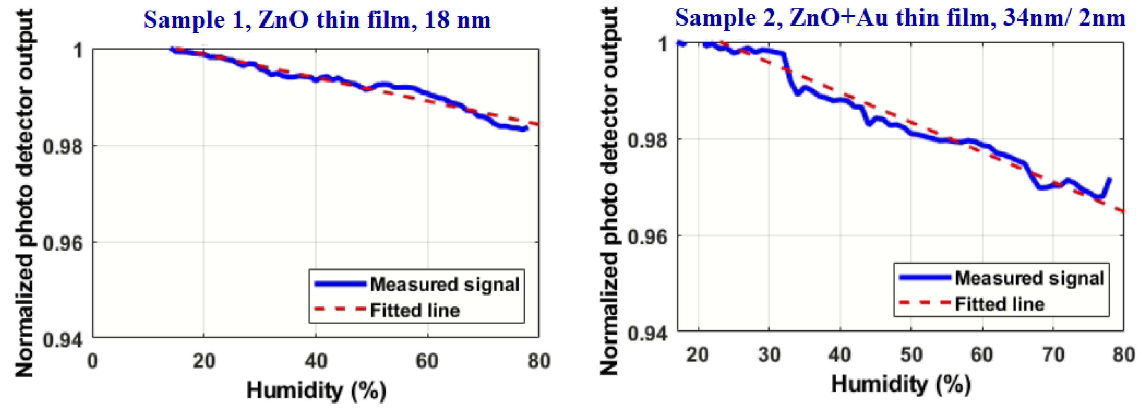
| 1 | Sputtering/thin film | ZnO | 18 nm |
| 2 | ZnO + Au | 34 nm + 2 nm | |
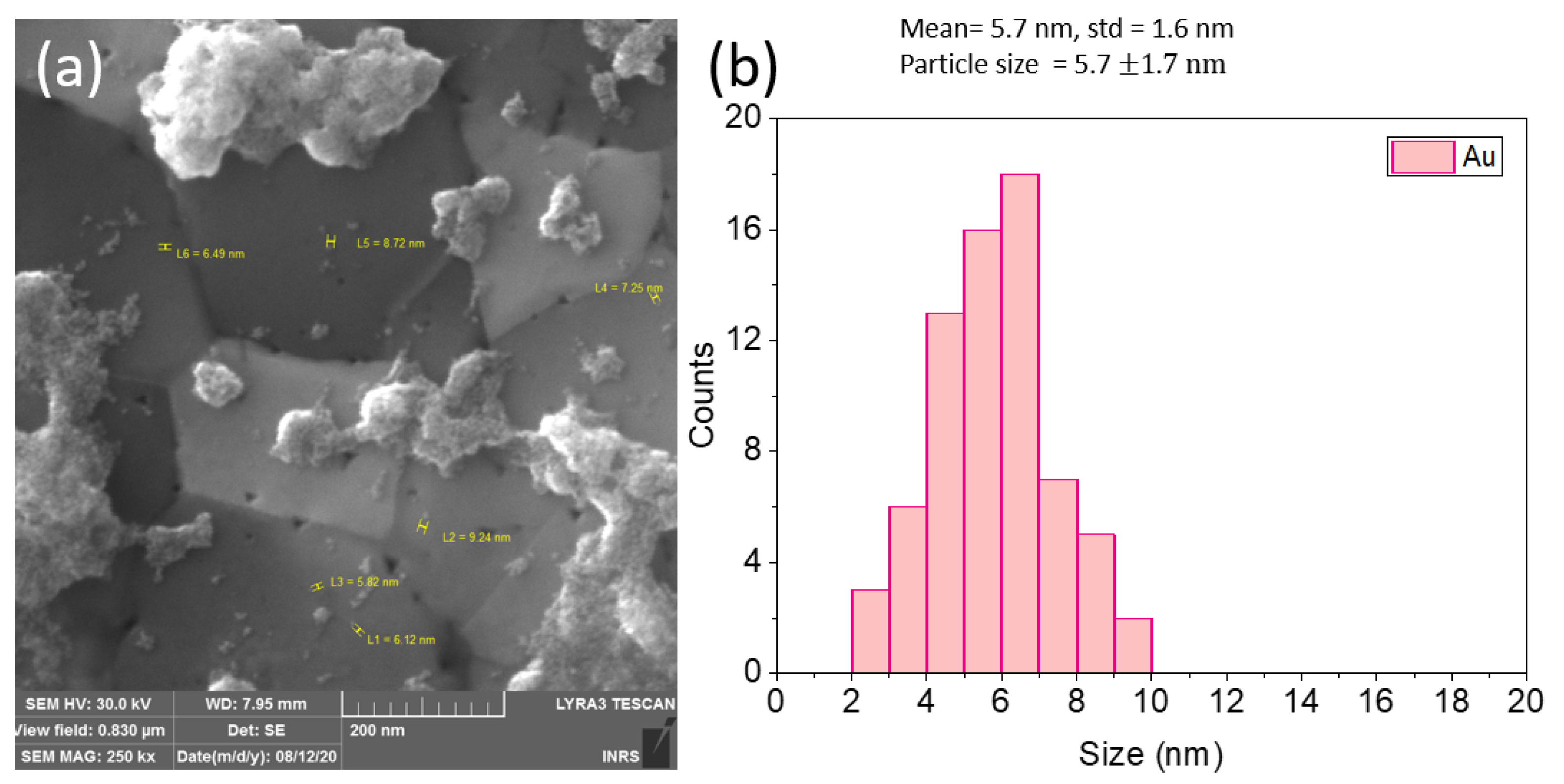
| 3 | PLAL/nanoparticles | Au | 5.7 ± 1.6 nm |
| 4 | ZnO | 38 ± 19 nm | |
| 5 | Au + ZnO | 42 ± 17 nm |
| Sample No. | Coating | Maximum Power Variation (%) | Linearity (%) | Sensitivity (uV/%RH) | Minimum Detectable Humidity (%RH) |
|---|---|---|---|---|---|
| 1 | ZnO (18 nm) | 1.7 | 0.94 | Low sensitivity | |
| 2 | ZnO + Au (34 nm + 2 nm) | 3.0 | 0.91 | ||
| 3 | AuNp | 29.9 | 0.97 | 71.6 | 0.3 |
| 4 | ZnONp | 38.9 | 0.95 | 143.6 | 0.1 |
| 5 | Au + ZnO Nps | 33.4 | 0.98 | <20 | 2 |
| Reference | Coating Material | Mechanism | Humidity Range | Sensitivity | Resolution | Linearity | Response Time | Strength Point |
|---|---|---|---|---|---|---|---|---|
| Y. Zhao et al. [30] | PVA | EW, U-bent probe, Wavelength variation | 15–85% | 318.1 pm/%RH | 0.0629% RH | 99% | NF | Excellent resolution |
| A. Vijayan et al. [37] | Co nanoparticles dispersed in polyaniline | EW, U-bent Optical power variation | 20–100% | 2 mV/%RH (between 35% to 80%) | NF | NF | 8 s rise/60 s fall | High sensitivity in a wide range |
| Z. Zhao et al. [31] | Silica doped with Methylene Blue | EW, U-bent Optical power variation | 1.1–70% | 0.087 dB/%RH (between 1.1% to 4.1%) | 0.062% RH (between 1.1% to 4.1%) | logarithmic | 20 s rise/180 s fall | Excellent resolution |
| S. K. Shukla et al. [34] | MgO | EW, U-bent Optical power variation | 5–80% | (0.037–0.015)/75 (W) 0.3 mW/%RH | NF | NF | NF | High sensitivity |
| J. Mathew et al. [32] | Agarose | EW, U-bent Optical power variation/wavelength optimized | 25–90% | 100 mdB/%RH at 1600 nm wavelength | NF | Linear | 50 ms rise/700 ms fall (60–90%) | High sensitivity, fast response, and recovery time |
| S. Khijwania et al. [21] | PVA dopped with CoCl2 | EW, U-bent, Optical power variation/ | 10–90% | 27 mV/%RH | NF | Linear | 1s | Very high sensitivity |
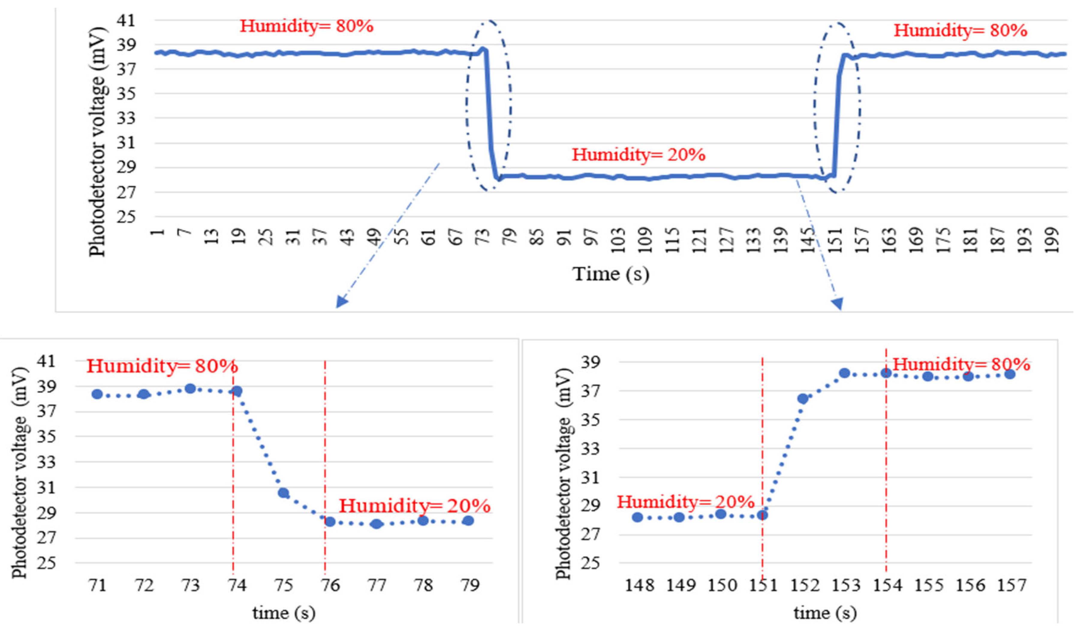
| This work | ZnO nanoparticles | EW excited surface polaritons | 10–80% | 143 µV/%RH | 0.1% RH | 95% in the whole range | 3 s rise/4 s fall (20–80%) | Very good resolution, Linear, Fast response, and recovery time |
Disclaimer/Publisher’s Note: The statements, opinions and data contained in all publications are solely those of the individual author(s) and contributor(s) and not of MDPI and/or the editor(s). MDPI and/or the editor(s) disclaim responsibility for any injury to people or property resulting from any ideas, methods, instructions or products referred to in the content. |
© 2023 by the authors. Licensee MDPI, Basel, Switzerland. This article is an open access article distributed under the terms and conditions of the Creative Commons Attribution (CC BY) license (https://creativecommons.org/licenses/by/4.0/).
Share and Cite
Afsharipour, E.; Malviya, K.D.; Montazeri, M.; Mortazy, E.; Soltanzadeh, R.; Hassani, A.; Rosei, F.; Chaker, M. Evanescent-Field Excited Surface Plasmon-Enhanced U-Bent Fiber Probes Coated with Au and ZnO Nanoparticles for Humidity Detection. Processes 2023, 11, 642. https://doi.org/10.3390/pr11020642
Afsharipour E, Malviya KD, Montazeri M, Mortazy E, Soltanzadeh R, Hassani A, Rosei F, Chaker M. Evanescent-Field Excited Surface Plasmon-Enhanced U-Bent Fiber Probes Coated with Au and ZnO Nanoparticles for Humidity Detection. Processes. 2023; 11(2):642. https://doi.org/10.3390/pr11020642
Chicago/Turabian StyleAfsharipour, Elnaz, Kirtiman Deo Malviya, Mohammadreza Montazeri, Ebrahim Mortazy, Ramin Soltanzadeh, Alireza Hassani, Federico Rosei, and Mohamed Chaker. 2023. "Evanescent-Field Excited Surface Plasmon-Enhanced U-Bent Fiber Probes Coated with Au and ZnO Nanoparticles for Humidity Detection" Processes 11, no. 2: 642. https://doi.org/10.3390/pr11020642