All articles published by MDPI are made immediately available worldwide under an open access license. No special
permission is required to reuse all or part of the article published by MDPI, including figures and tables. For
articles published under an open access Creative Common CC BY license, any part of the article may be reused without
permission provided that the original article is clearly cited. For more information, please refer to
https://www.mdpi.com/openaccess.
Feature papers represent the most advanced research with significant potential for high impact in the field. A Feature
Paper should be a substantial original Article that involves several techniques or approaches, provides an outlook for
future research directions and describes possible research applications.
Feature papers are submitted upon individual invitation or recommendation by the scientific editors and must receive
positive feedback from the reviewers.
Editor’s Choice articles are based on recommendations by the scientific editors of MDPI journals from around the world.
Editors select a small number of articles recently published in the journal that they believe will be particularly
interesting to readers, or important in the respective research area. The aim is to provide a snapshot of some of the
most exciting work published in the various research areas of the journal.
For a wind energy system, main speed-increasing gearboxes, pitch drives and yaw drives are composed of a multistage planetary gear system. However, inevitable errors in the manufacturing and assembling of the gears lead to uneven load of distribution in the planetary gear system; thus, its service life and reliability decrease greatly, which would eventually affect the normal operation of the whole wind power system. In this study, a dynamic load sharing model of pitch drive is established with a lumped-parameter method. Given the manufacturing and assembly errors and central floating gear, the dynamic equations for each component, the stiffness matrix and damping matrix, the dynamic load sharing coefficient and the floating displacement of the sun gear are obtained according to the dynamic meshing force and damping load. Furthermore, the load sharing coefficient for external and internal meshing of the pitch drive for a 2 MW wind turbine with a three-stage planetary gear are achieved. Then, the floating displacement of the sun gear and the displacement of other gears are also obtained. Moreover, the influence of both external and internal meshing stiffness, the eccentric error and tooth frequency error for all components on the load sharing coefficient of all stages are investigated. Lastly, the theoretical components displacement of this model is compared with experiment results of the pitch drive under 50%, 100% and 150% rated torque in a test rig; the correctness of the model is verified by the experiment results.
A planetary gear is characterized by a high speed ratio, and its input torque is split into several parallel paths among planetary gears in the same stage, so its structure is more compact than others. Therefore, it is widely applied in fields such as aviation, automobile, wind turbine, etc. In addition, greater torque and smaller volume can be achieved by applying a multistage planetary gear system. All main gearboxes, pitch drives and yaw drives for the MW wind turbine comprise a multistage planetary system. However, unavoidable errors during the manufacture and assembling process cause unequal loads among the planetary gears and affect its reliability and operating life [1]. Therefore, it is essential to analyze load sharing characteristics of the planetary gearboxes in wind power systems.
Some researchers have investigated the load sharing of planetary gear systems. Iglesias et al. [2,3,4] considered the tangential and radial pin hole position error, fixed and floating central gears of a single-stage planetary gear system central gear floating. The results showed that the load sharing characteristics are better with the floating central gear, and the influence of the radial position error on the load sharing coefficient is larger than that of the tangential position error. Zhiliang Xu et al. [5] considered position errors of a gear pair. The results showed that suitable position errors can improve the load sharing condition by 10% if position errors change from 0.1 to 0.2 mm. Lokaditya Ryali et al. [6] established a dynamic load distribution model for a single-stage planetary gear system, and studied the effect of system parameters such as meshing phase, tooth modifications and contact ratio on the dynamic characteristics of the system. Kim et al. [7,8] analyzed the impact of increasing torque and rotation direction changing on the dynamic load sharing performance of planetary gearboxes through experiments. It showed that the increasing torque can improve the load sharing characteristics. Jungang Wang et al. [9] established a dynamics model for a multistage planetary gear system to study the load-sharing performance under the interaction of random input speed and internal excitation. The results showed that the fluctuation of the load sharing coefficient in the first-stage is more intense; thus, it is necessary to improve load distribution among gear pairs in the first-stage, which reduces vibration and prolongs the life.
Furthermore, some studies focused on load sharing measures to reduce the uneven load distribution. Julian Theling et al. [10] presented a method which combines a structural optimization with tooth contact analysis for planetary gearboxes. The results showed that the optimized geometry is capable of reducing the excitation and improving the load sharing behavior. Woo-Jin Chung et al. [11] analytically investigated the effects of floating components on the load sharing characteristics and the strength of planetary gearboxes with non-torque load and carrier pinhole position errors. The results implied that the load sharing characteristics of planetary gearboxes are improved by floating components. Zhixin Fan et al. [12] focused on flexible ring gears based on shell and Timoshenko beam theory. The results indicated that the flexible ring gear sharply reduces dynamic loads and uneven load distribution of the system. Lokaditya Ryali et al. [13] combined finite element input/output shafts and carrier in a computational model of planetary gear sets. The results showed that flexible carriers improve the load sharing among planetary gears.
In addition, other researchers also explored the dynamic characteristics and load distribution of planetary gear systems in a wind turbine gearbox. Young-Jun Park et al. [14] used a 1/4 scale-down model of a main speed increasing gearbox for a 2-MW wind turbine and conducted a parametric study with a three-dimensional model. The results of the analysis showed that the radial force and moment were major non-torque elements that affect the load sharing of planet gears. Magnitudes, positions and phases of pinhole position errors also affect the load sharing characteristics of the planet gears significantly. When non-torque loads and pinhole position errors acted together, the influence of pinhole position errors was greater than that of the non-torque loads. Ho-gil Yoo et al. [15] designed a flexible pin to improve load sharing of the main speed increasing gearbox for a wind turbine gearbox. The results showed that the load sharing performance improved significantly with the flexible pin. Additionally, the flexible pin design ensured that all components satisfied the strength requirement.
However, all the above studies are related to the load sharing behavior of the main speed increasing gearboxes in wind turbines; there are few studies focused on the pitch drive in wind turbines. Accordingly, it is necessary to investigate the load sharing performance of the planetary gear system of the pitch drive in wind power systems. In this study, a lumped-parameter model for a pitch drive is developed to explore the dynamic load sharing characteristics. This article is organized as follows: In Section 2, the dynamic load sharing model of planetary gear systems is briefly introduced. Section 3 analyzes the dynamic load sharing coefficient and displacement of a pitch drive with a three-stage planetary gear system and discusses the impact of meshing stiffness, eccentric errors and tooth frequency errors in the load sharing behaviors. A comparison of the theoretical dynamics behavior and the experiment result is set out in Section 4.
2. Dynamic Load Sharing Model of the Pitch Drive for the MW Wind Turbine
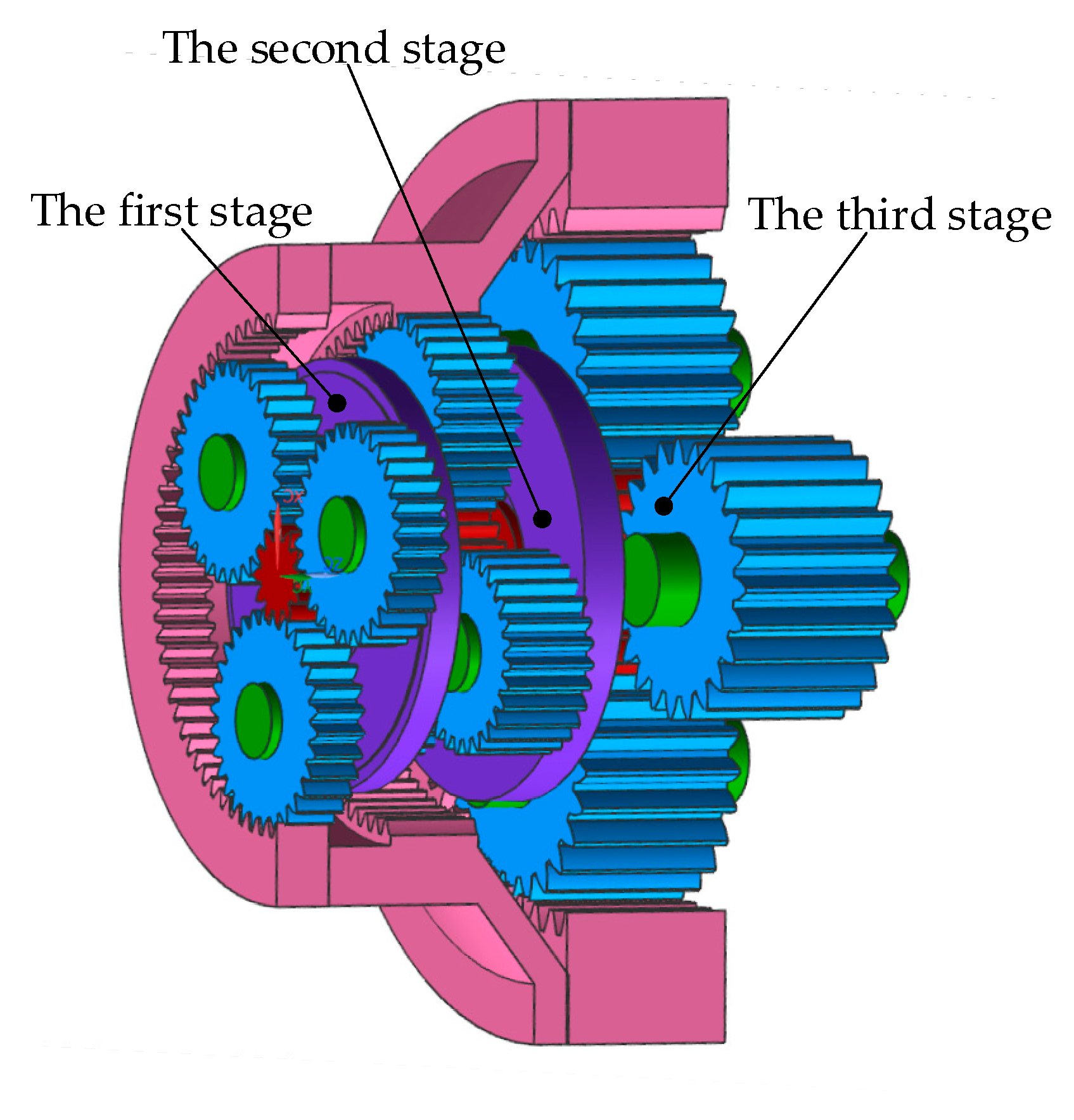
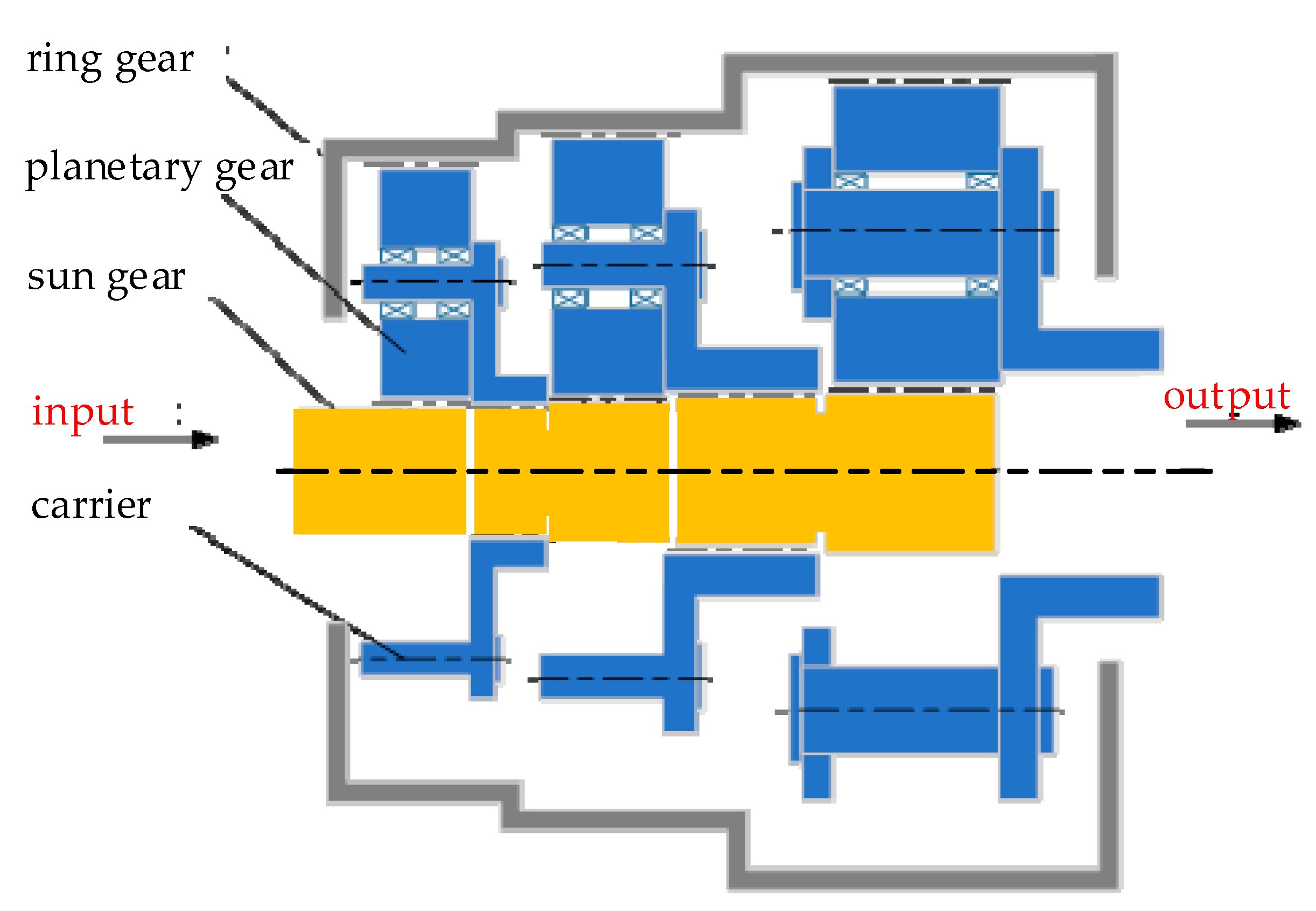
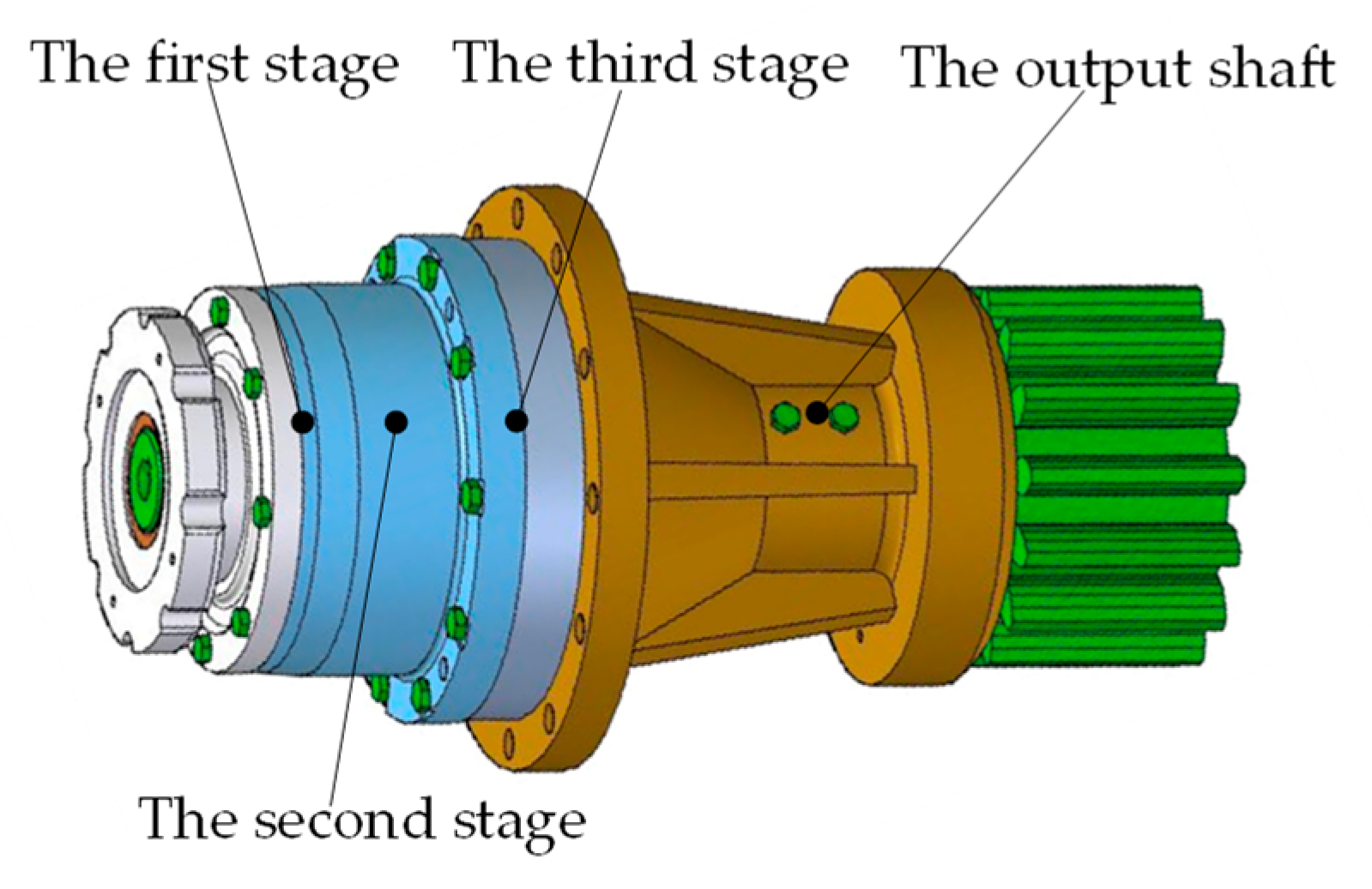
The pitch drive consists of several stages of a planetary gear system connected in series. Each stage is composed of a sun gear, planetary gears, a ring gear and a carrier. The power of the pitch drive is inputted from the sun gear in the first stage and transferred through planetary gears to the carrier, which is connected to the sun gear in next stage by splines. The power is outputted to the carrier in the last stage. Consequently, mutual supports are created between the sun gear in the next stage and the front carrier. Figure 1 shows the three-dimensional structure of a three-stage planetary gear system, and Figure 2 shows how they are connected.
2.1. Lumped-Parameter Model of the Planetary System for MW Wind Turbines
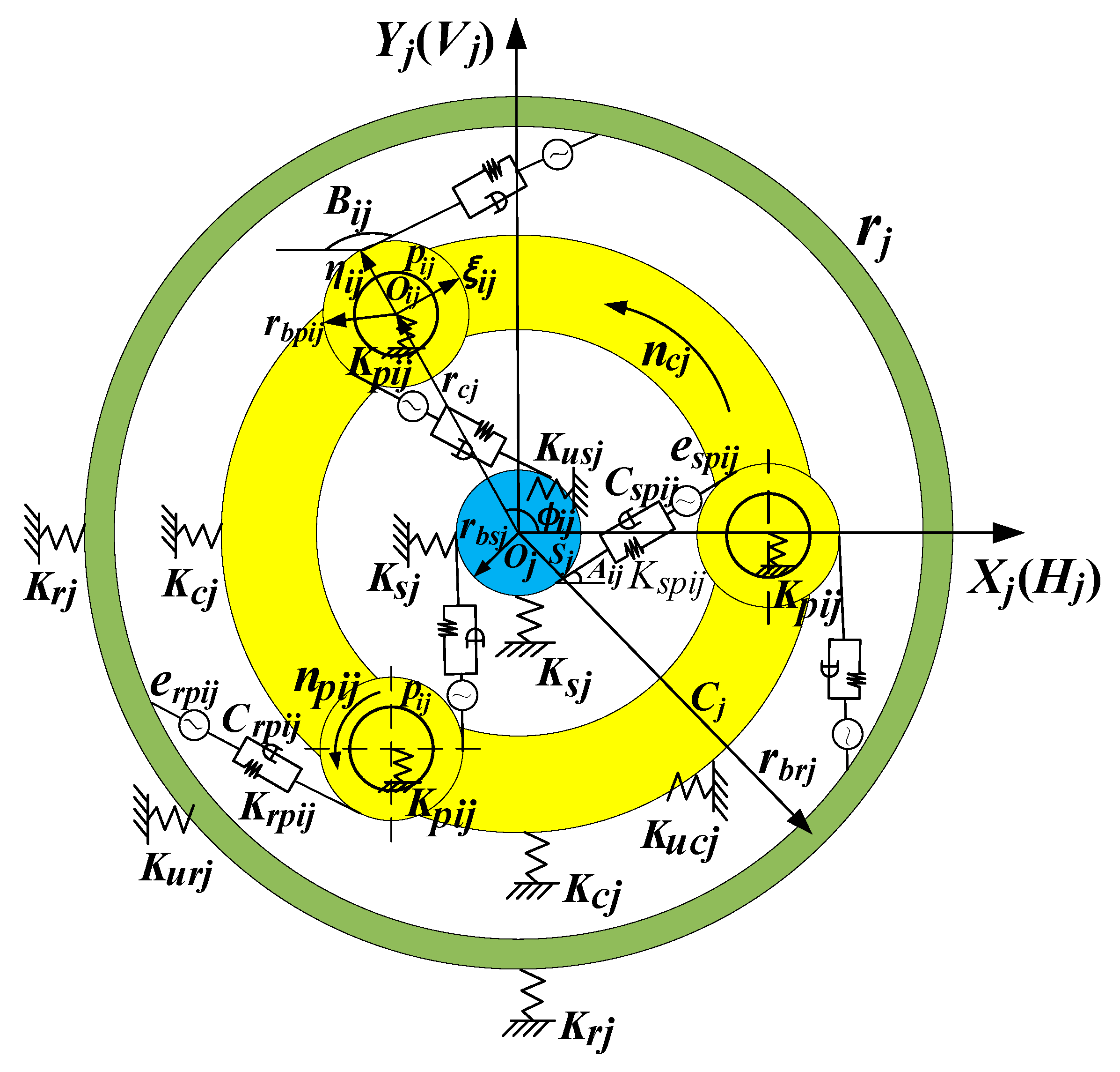
The lumped-parameter dynamics model of a single-stage planetary gear system is shown in Figure 3. In this model, as its main components are considered rigid, the gear meshing is modeled as a spring with time-varying stiffness, a damping and an equivalent error along the meshing line, where the equivalent error is connected with the spring and damping in parallel. Additionally, other supporting springs are linear. In the same stage, all planetary gears are assumed to be identical with the mass, inertia, gear profile error and gear meshing stiffness. However, the mass, inertia, gear profile error and gear meshing stiffness of planetary gears in different stages are not the same. Hj-Oj-Vj, ξij-Oij-ηij and Xj-Oj-Yj represent the coordinates of the sun gear, the ith planetary gear and the carrier in the jth stage, respectively. The axial displacement of all the components is not taken into consideration.
In Figure 3, Ksj, Krj, Kpij and Kcj represent the support stiffness of the sun gear, ring gear, ith planetary gear and the carrier in jth stage, respectively, and Kusj, Kurj, Kucj are the rotational stiffness of the sun gear, the ring gear and carrier, respectively. The meshing between the sun gear and the planetary gear is defined as external meshing, and that between the ring gear and the planetary gear is defined as internal meshing. Kspij and Krpij are the stiffness of the external meshing and the internal meshing, respectively. Cspij and Crpij are the damping of the external meshing and the internal meshing, respectively. espij and erpij are the equivalent error of the external meshing and the internal meshing, respectively. upij, usj and ucj are the rotational displacement of the planetary gear, the sun gear and the carrier in the jth stage, respectively. usj = rbsj × θsj, upij = rbpij × θpij, and ucj = rcj × θcj.
2.2. Errors in the Model
2.2.1. Manufacturing and Assembling Errors
Because of the manufacturing and assembling errors, the load is not equally shared among the planetary gears of the planetary gear system. The considered manufacturing errors in this paper are the eccentric error and tooth frequency error.
When the previous meshing for the tooth pair ends and the next meshing starts, the tooth profile deviation and the base pitch error of the gear cause the load varying along the meshing line. These two types of errors are defined as the tooth frequency error, so it is necessary to consider the influence of the tooth frequency error εspij on the dynamic load sharing. The tooth frequency error εspij of the external meshing and εrpij of the internal meshing are valued by their tolerance.
Moreover, the assembling error is only considered for the ring gear for the floating carrier and sun gear. The eccentric and assembling errors considered in this study are shown in Table 1. The symbols E and A represent the manufacturing error and assembling error, respectively. βsj, βpj, βcj, and βrj are the phase angles of the manufacturing error E for the sun gear, the planetary gear, the carrier and the ring gear, respectively. γrj is the phase angle of the assembly error Arj.
2.2.2. Equivalent Meshing Error
The meshing error consists of the above manufacturing and assembly errors of different components. Thus, it is vital to determine the equivalent meshing error by transforming these errors along the meshing line [16]. The equivalent meshing error espij between the sun gear and the ith (i = 1, 2, …, n) planetary gear and the meshing error erpij between the ring gear and the ith planetary gear are calculated as follows:
where ωsj, ωcj and ωpj are the angular velocities of the sun gear, the carrier and the planetary gear in the jth stage, respectively. φij is the phase angle of the ith planetary gear in the jth stage,
. αwj and αnj are the external and internal meshing angles in the jth stage, respectively. εspij is the tooth frequency error of the external meshing gear, and εrpij is the tooth frequency error of the internal meshing gear.
2.2.3. Floating Error
The radial flotation of the central member causes the displacement varying along the internal and external meshing lines in the planetary gear system, so the floating displacement also needs to be transformed into the floating error [17]. Hsj and Vsj are the floating displacements of the sun gear in the horizontal and vertical directions in the Hj-Oj-Vj coordinates, respectively. Xcj and Ycj are the floating displacements for the carrier in the horizontal and vertical directions in the Xj-Oj-Yj coordinates, respectively. The ring gear is fixed, so its displacement is zero. The floating displacements Hsj and Vsj of the sun gear are incorporated in the floating error Δsij of the external meshing, and Xcj and Ycj are incorporated in the floating error Δcisj of the external meshing and incorporated in the floating error Δcirj of the internal meshing. These errors are indicated as below:
where Aij represents the azimuth angle of the meshing line between the sun gear and the ith planetary gear, , and Bij represents the azimuth angle of the meshing line between the ith planetary gear and the ring gear, .
2.3. Dynamic Load and Damping Force along the Meshing Line
All the time-varying meshing stiffness [18], the equivalent meshing error, the floating error and the tooth frequency error of planetary gears are considered in the dynamic load sharing model of the pitch drive. The dynamic load Wspij of the external meshing and Wrpij of the internal meshing are presented as follows:
where Kspij is the time-varying stiffness of the external meshing, and Krpij is the time-varying stiffness of the internal meshing.
The time-varying meshing stiffness can be approximately expressed by the Fourier series expansion as follows [17]:
where ko is the average meshing stiffness of the gear pair, kmin is the meshing stiffness of a single tooth pair and kmax is the meshing stiffness of double tooth pairs. ICR is the contact ratio of the gear pair and ω is the meshing frequency.
By substituting the Equations (1) and (2) into the Equation (3), the dynamic meshing force of the external and internal meshing can be calculated as follows:
Corresponding to Wspij and Wrpij, the damping force Dspij of the external meshing and Drpij of the internal meshing are the following:
where Kspij and Krpij are the time-varying stiffness of the external and internal meshing, respectively, and Cspij and Crpij are the damping coefficients of the external and internal meshing, respectively.
The damping coefficient Cspij of the external meshing and the damping coefficient Crpij of the internal meshing are the following:
where ζ is the damping ratio, which is 0.007 for steel, and msj, mpij, and mrj are the mass of the sun gear, the ith planetary gear and the ring gear, respectively.
2.4. Dynamics Model of the Planetary Gear System
The dynamics model of the system is
For the pitch drive, the displacement vector is as follows:
The mass matrix M for the system is the following:
where msj is the mass of the sun gear in the jth stage, mpij is the mass of the ith planetary gear in the jth stage, and mrj is the carrier mass in the jth stage.
For each stage, the dynamic equation [19] for the sun gear, the planetary gears and the carrier in the translation and torsional directions are deduced as follows:
The sun gear:
The ith planetary gear:
The carrier:
where: T is the input torque of the sun gear, Kpij is the support stiffness of the ith planetary gear, Kucj is the torsion stiffness of the spline and Kcj is the support stiffness of the carrier.
Based on dynamic equations, the stiffness matrix Kj for the whole planetary gear system in the jth stage is shown in Equation (15).
where , , , , , , and .
Similar to the stiffness matrix, the overall damping matrix Cj of the whole planetary gear system in the jth stage is shown in Equation (16).
Each sub-matrix of the damping matrix Cj of the planetary gear system in the jth stage in Equation (16) is shown as follows:
where .
Then, the overall stiffness matrix and the damping matrix of the pitch drive are integrated by the stiffness matrix and the damping matrix of each stage, which are as follows:
2.5. Dynamic Load Sharing Coefficient and Sun Gear Floating Displacement
The dynamic load sharing coefficient indicates an unequal degree of the load sharing among planetary gears in the system. The larger the load sharing coefficient is, the more uneven load sharing is then indicated. The displacement vector u can be obtained through numerical solution of the differential Equation (9) with the Runge–Kutta method. Then, the dynamic load can be achieved by substituting the displacements into Equation (5).
With both the external meshing and internal meshing load for each planetary gear, the load sharing coefficient for the external and internal meshing is able to be obtained separately. The tooth frequency cycle is defined as the period when the sun gear rotates one tooth. In the kth tooth frequency cycle, the load sharing coefficient Bspij of the external meshing and Brpij of the internal meshing of the ith planetary gear in the jth stage can be obtained with the maximum dynamic load:
In the whole operating process, the dynamic load sharing coefficients Bspj and Brpj of the external and internal meshing are the maximum values of all planetary gears, which can be calculated separately as follows:
The sun gear floats near its ideal central position because of the error excitation, and its radial floating displacement is as follows:
3. Load Sharing Analysis of the Pitch Drive for a 2 MW Wind Turbine
3.1. The Pitch Drive of a 2 MW Wind Turbine
The example analyzed in this study is the pitch drive with a three-stage planetary gear system in a 2 MW wind turbine. The main function of the pitch drive serves as pitching and adjusting the output power of the wind turbine. Its parameters are listed in Table 2. There are three planetary gears equally placed in each stage, and the phase angle of first planetary gear is 2π/3.
In the first stage, the sun gear is applied by an external torque from the driving motor, so it only has a rotational movement, and Hs1 and Vs1 are zero. Each planetary gear and carrier has the lateral, vertical and rotational movements, and the ring gear in every stage is fixed by the flange. Thus, there are 13 degrees of freedom in the first stage.
In addition, each of the sun gears, the planetary gear and the carrier in the second and third stage, has three degrees of freedom; there are 15 degrees of freedom in the second or third stage with three planetary gears. As a result, there are a total of 43 degrees of freedom in dynamic load sharing model of pitch drive.
The supporting and meshing stiffness in all stages are listed in Table 3, and the values of the considered errors are shown in Table 4.
3.2. Dynamic Load Sharing Coefficient
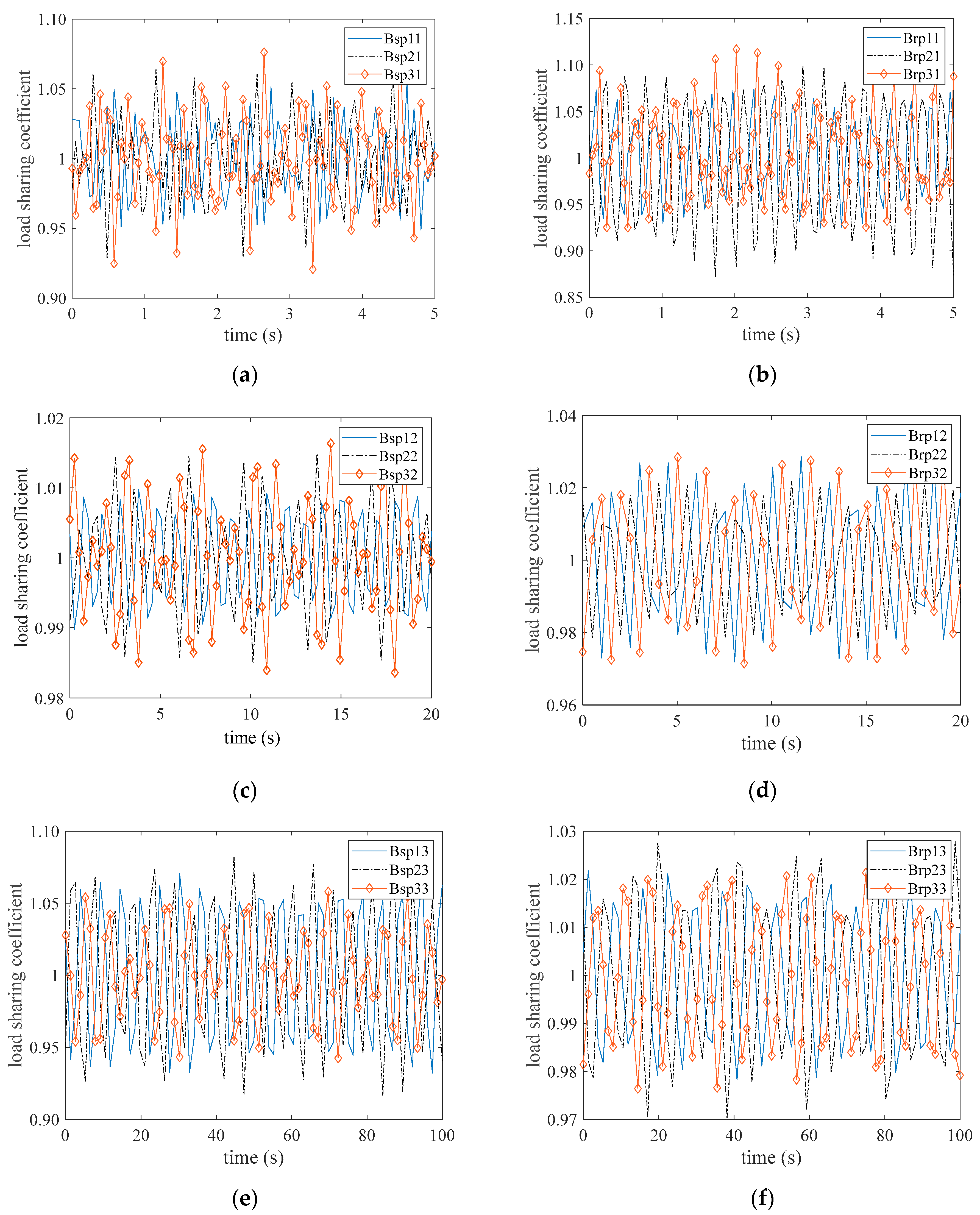
The load sharing coefficients of the internal and external meshing in three stages calculated based on the model above are shown in Figure 4a–f, respectively. The dynamic load sharing coefficients vary periodically with the gears operation. In the first stage, the dynamic load sharing coefficient Bsp1 of the external meshing is 1.076 and Brp1 of the internal meshing is 1.116. Then, Bsp2 of the external meshing is 1.016 and Brp2 of the internal meshing is 1.028 in the second stage. Moreover, the dynamic load sharing coefficient Bsp3 is 1.092 and Brp3 of the internal meshing is 1.027 in the third stage.
3.3. Floating Displacement of the Sun Gear
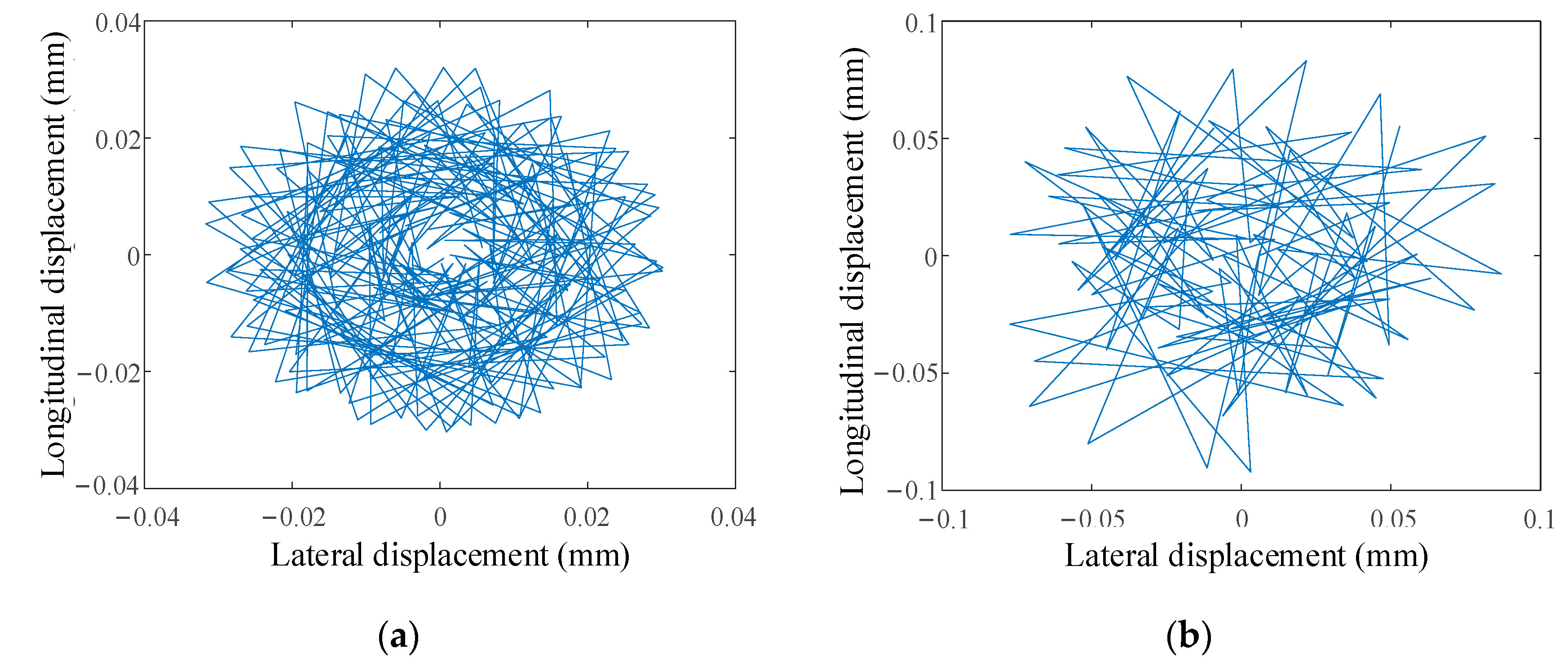
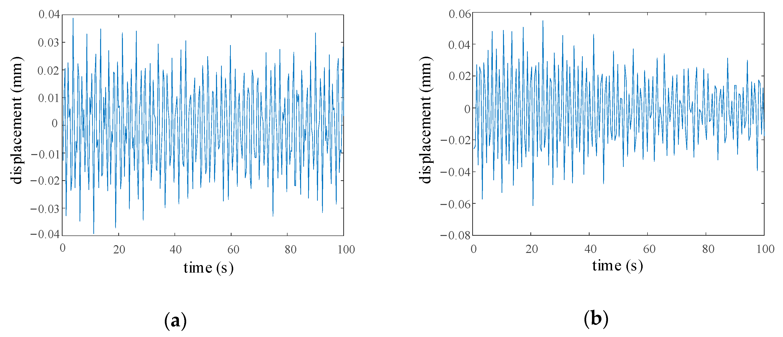
The sun gear deviates from the original position with fluctuation. As the sun gear in the first stage of the pitch drive of wind turbines is radially fixed, it cannot float. As a consequence, only the floating displacement of sun gears in the second and third stage is researched in this study. The longitudinal and lateral floating displacements in the second and third stage are shown in Figure 5a,b, respectively. The radial synthetic floating displacement of the sun gear is 0.028 mm in the second stage and 0.087 mm in the third stage.
3.4. Dynamic Displacement of the Gears
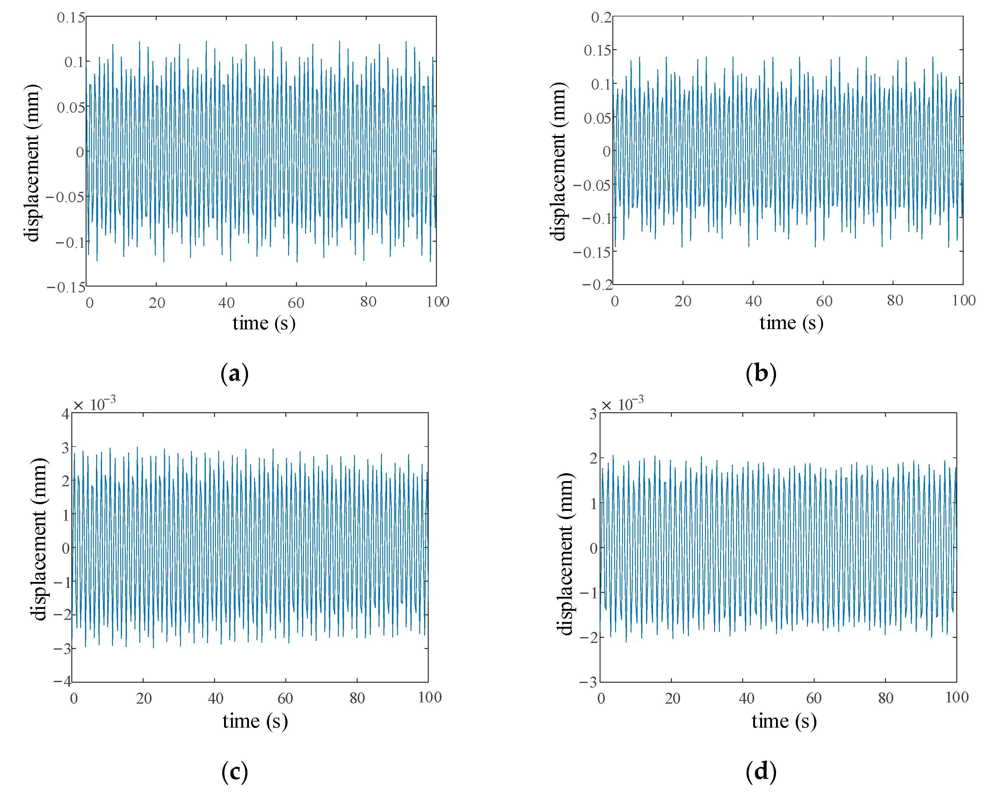
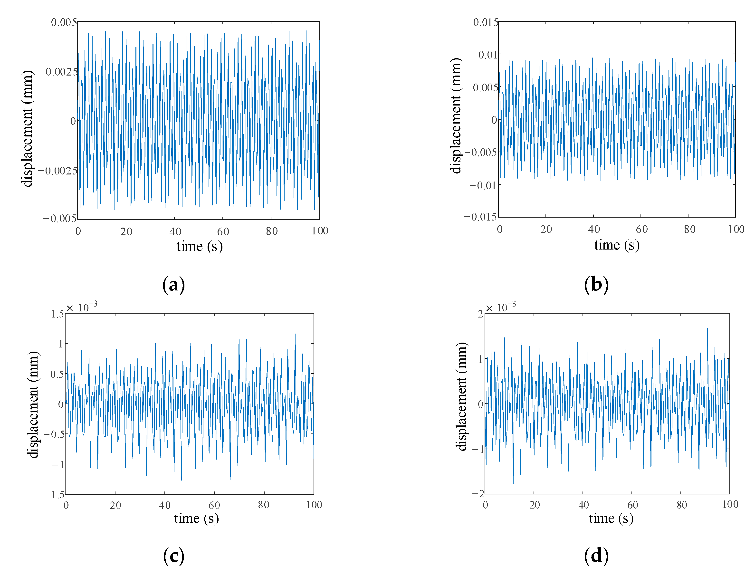
The time-domain displacement of each component in each stage is analyzed in this section. The time-domain displacement of the components in certain directions in the first, second and third stage are shown in Figure 6, Figure 7 and Figure 8, respectively. Owing to the rotation torque in every stage, the rotational displacement of the planetary gear is larger than its radial displacement. Additionally, the displacement of the sun gear, the planetary gear and the carrier in the third stage is greater than that in the first and second stages, on account of the largest torque in the third stage.
3.5. The Displacement of Carrier under Different Loads
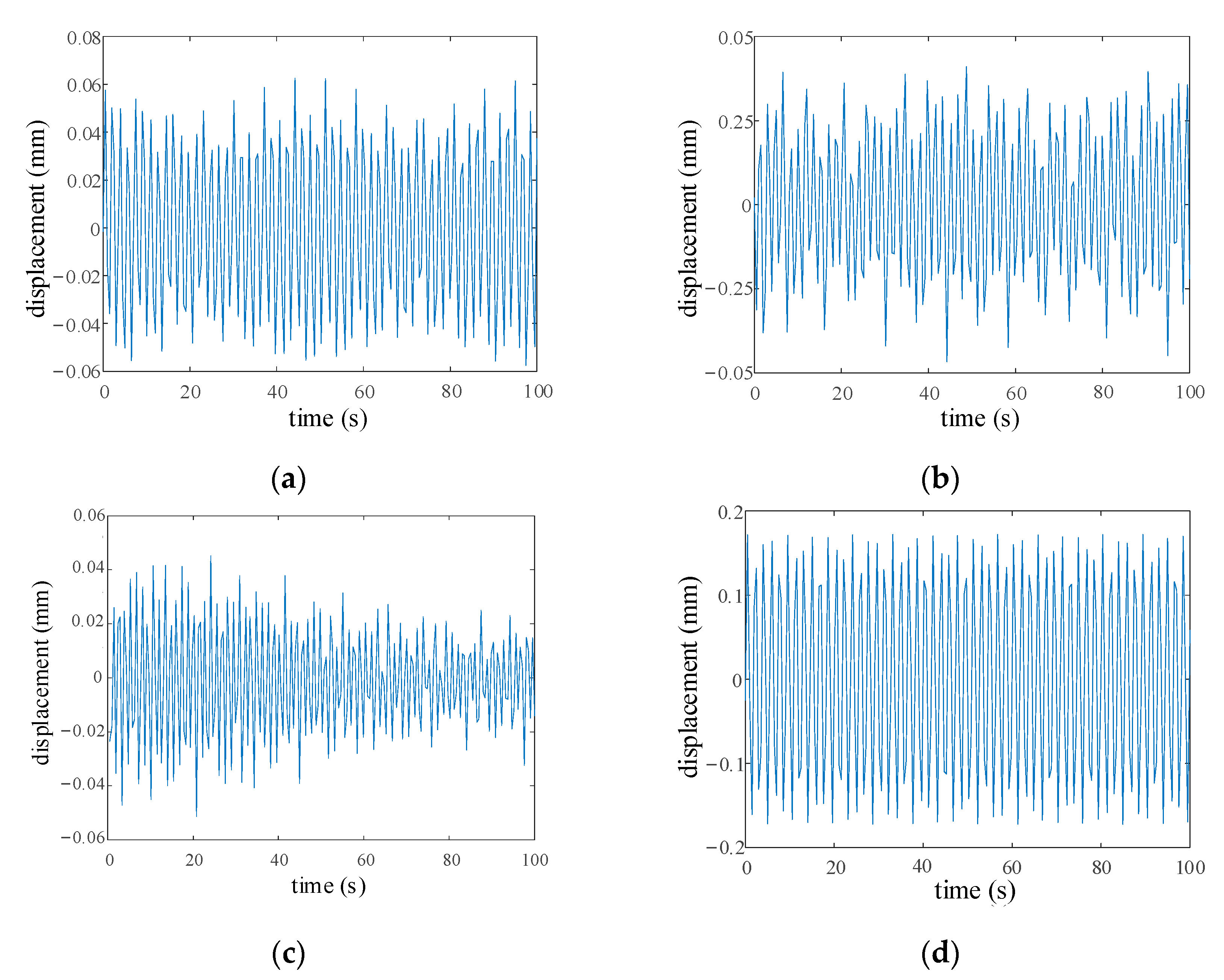
In order to analyze displacement under different loads, the displacement of the carrier in the third stage under 50% and 150% rated torque are also calculated in the time-domain. The vertical displacement Yc3 of the carrier in the third stage under 50% and 150% rated torque are shown in Figure 9a,b, respectively. In addition, the vertical displacement Yc3 of the carrier under the rated torque is shown in Figure 8c. It can be seen from these figures that the displacement of the carrier improves slowly with the load increment.
3.6. Analysis of the Parameter Sensitivity
3.6.1. The Effect of the Meshing Stiffness on the Load Sharing Coefficient
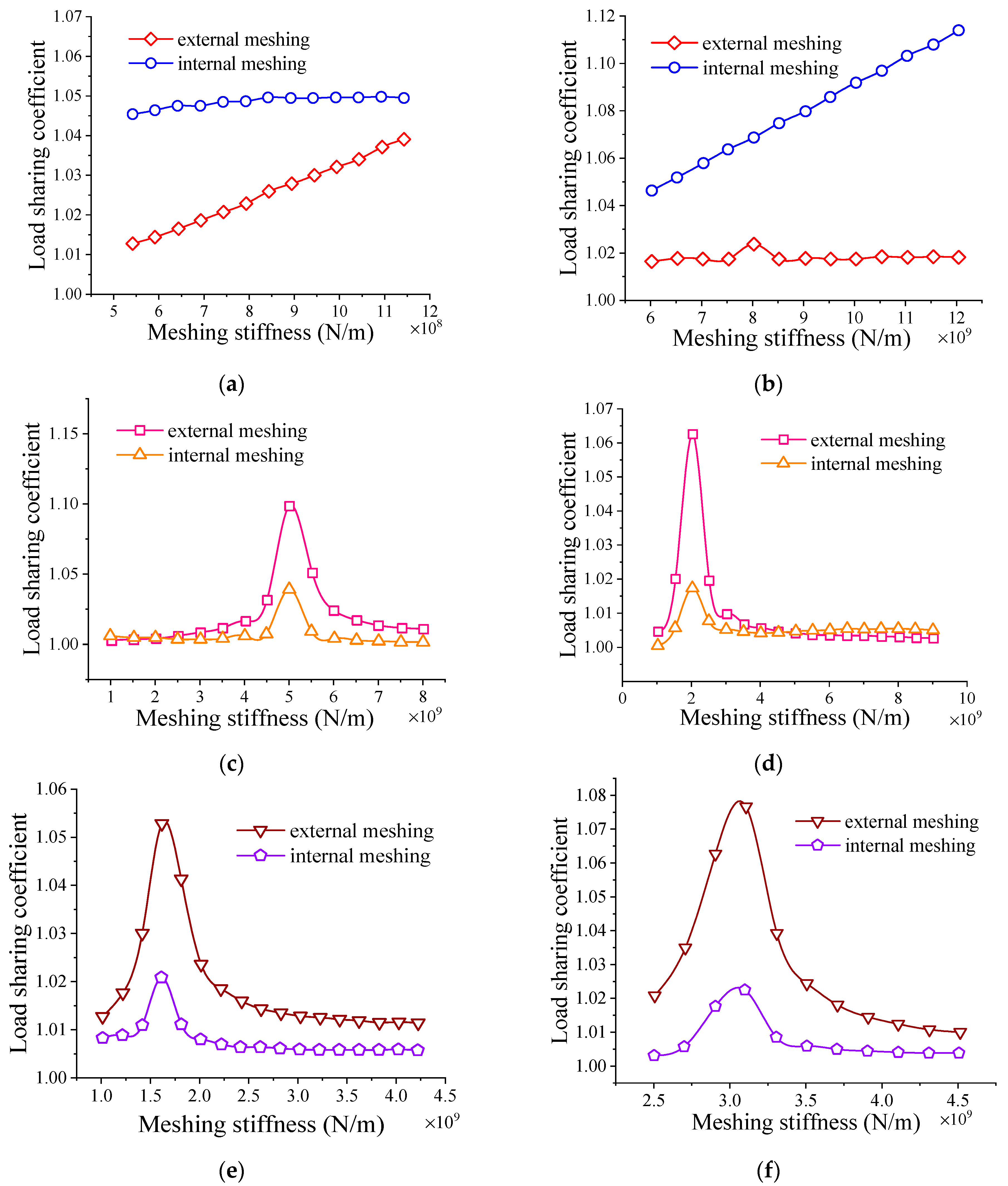
The effect of external and internal meshing stiffness on the dynamic load sharing coefficient for the external and internal meshing in three stages of pitch drive is shown in Figure 10a–f, respectively. The time-varying meshing stiffness is replaced by the average meshing stiffness in this study. In the first stage, as external meshing stiffness increase, the dynamic load sharing coefficient of the internal meshing increases slowly but dynamic load sharing coefficient of the external meshing grows more significantly, as Figure 10a shows. For the internal meshing stiffness in Figure 10b, when the internal meshing stiffness turns to 8 × 10⁹ N/m, the load sharing coefficient of the external meshing increases slightly. However, the load sharing coefficient of the internal meshing rises largely with the improvement in the internal meshing stiffness.
In the second and third stages, all the load sharing coefficients are under the impact of the saltation when the external and internal meshing stiffness reaches a specific value, as shown in Figure 10c–f, respectively.
The load sharing coefficients for each stage increase rapidly to the maximum and then gradually decrease and tend to be stable. In the second stage, the load sharing coefficients for the external and internal meshing are similar except for the saltation area. In the third stage, the load sharing coefficients of the external meshing are greater than those of the internal meshing as the stiffness of meshing increases. Therefore, both the internal and external meshing stiffness in the saltation areas should be avoided in the process of gear system design.
3.6.2. The Effect of Eccentric Error on the Load Sharing Coefficient
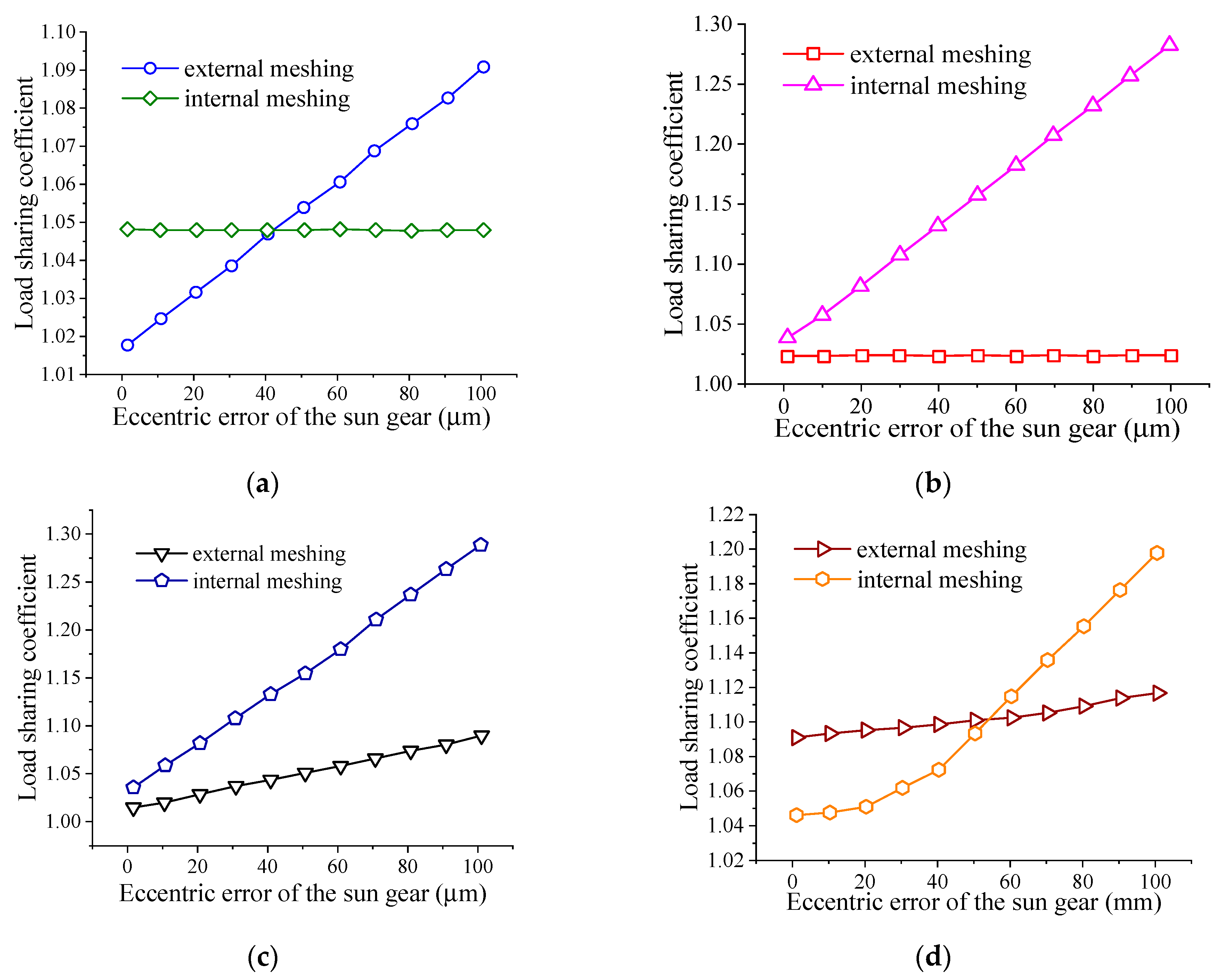
The impact of the eccentric error of all components on the load sharing coefficients of the external and internal meshing in the first stage is shown in Figure 11a–d, noting that results for other stages are the same as in the first stage.
With eccentric error increment of the sun gear, the load sharing coefficient of the external meshing augments significantly. The load sharing coefficient of the internal meshing remains unchanged because the sun gear does not get incorporated into the internal meshing. Similar to the sun gear, the eccentric error of the ring gear has an obvious effect on the internal meshing, as shown in Figure 11a,b.
Moreover, the load sharing coefficients of both the internal and external meshing augment with eccentric error increment of the planetary gear and the carrier, as shown in Figure 11c,d. Therefore, the eccentric error of the two components should be effectively controlled to improve the load sharing behavior of the system.
3.6.3. The Effect of Tooth Frequency Error on the Load Sharing Coefficient
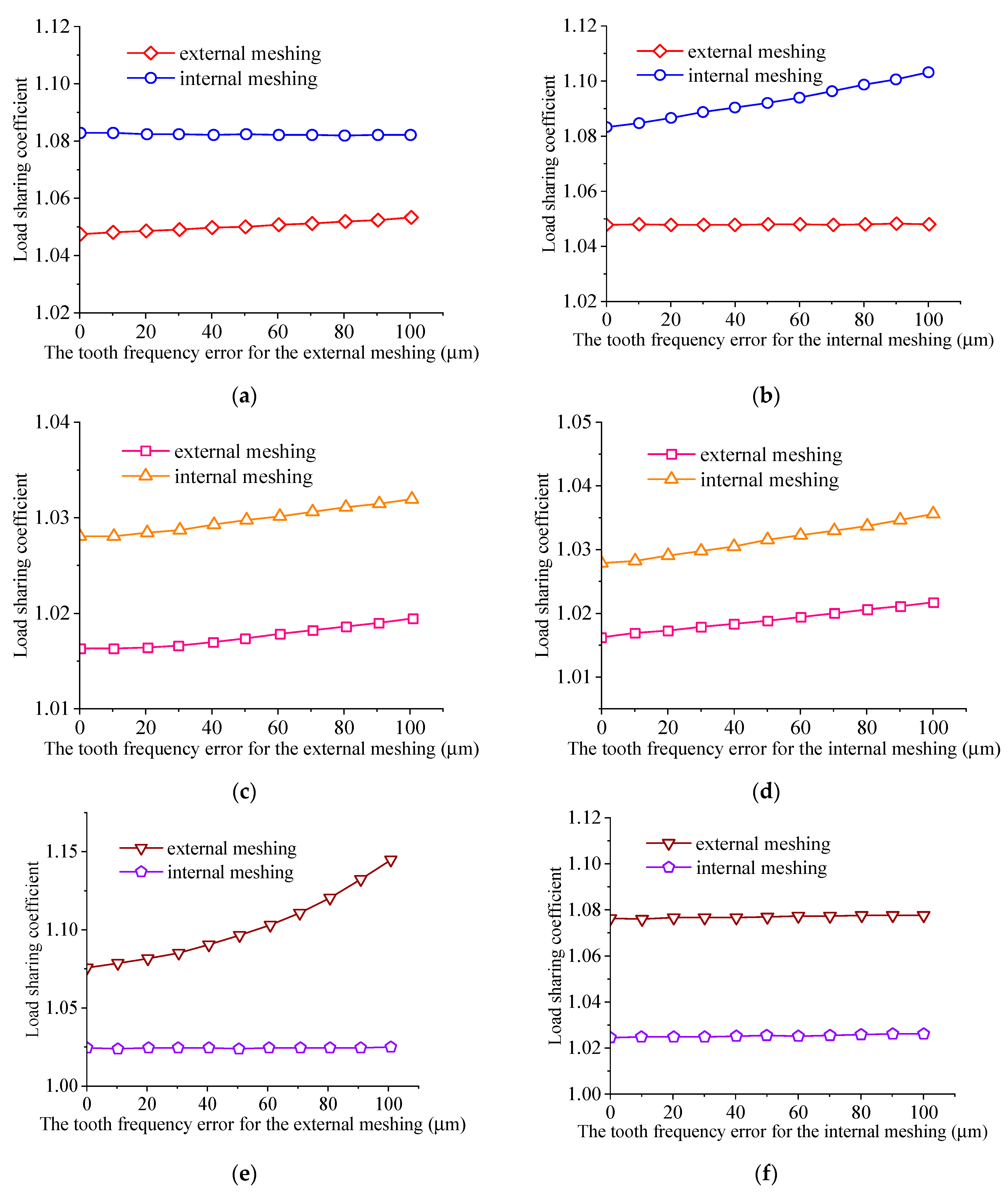
The impact of the tooth frequency error on the load sharing coefficient of the external and internal meshing in three stages is shown in Figure 12a–f. In the first stage, the dynamic load sharing coefficient of the external meshing increases slowly with an augment in the tooth frequency error of the external meshing, while that of the internal meshing remains unchanged. When the tooth frequency error of the internal meshing grows, the dynamic load sharing coefficient of the internal meshing also improves significantly, while that of the external meshing is basically unchanged, as shown in Figure 12a,b. The influence of the tooth frequency error in the second stage is shown in Figure 12c,d. Both the load sharing coefficients of the external and internal meshing promote gradually as the tooth frequency error augments.
However, in the third stage, the load sharing coefficient of the external meshing augments dramatically with the tooth frequency error for the external meshing increasing, but it remains unchanged as with the increment of the tooth frequency error of the internal meshing. In addition, the load sharing coefficients for meshing do not change with the variation of the tooth frequency error of the both meshing.
It can be seen that the tooth frequency error of the external meshing bears more impact on the external meshing load sharing, and the tooth frequency error of the internal meshing mainly affects the internal meshing load sharing, while sometimes the error of both the external and internal meshing interacts.
4. Dynamics Experiments of Pitch Drive
4.1. Test Rig of Pitch Drive
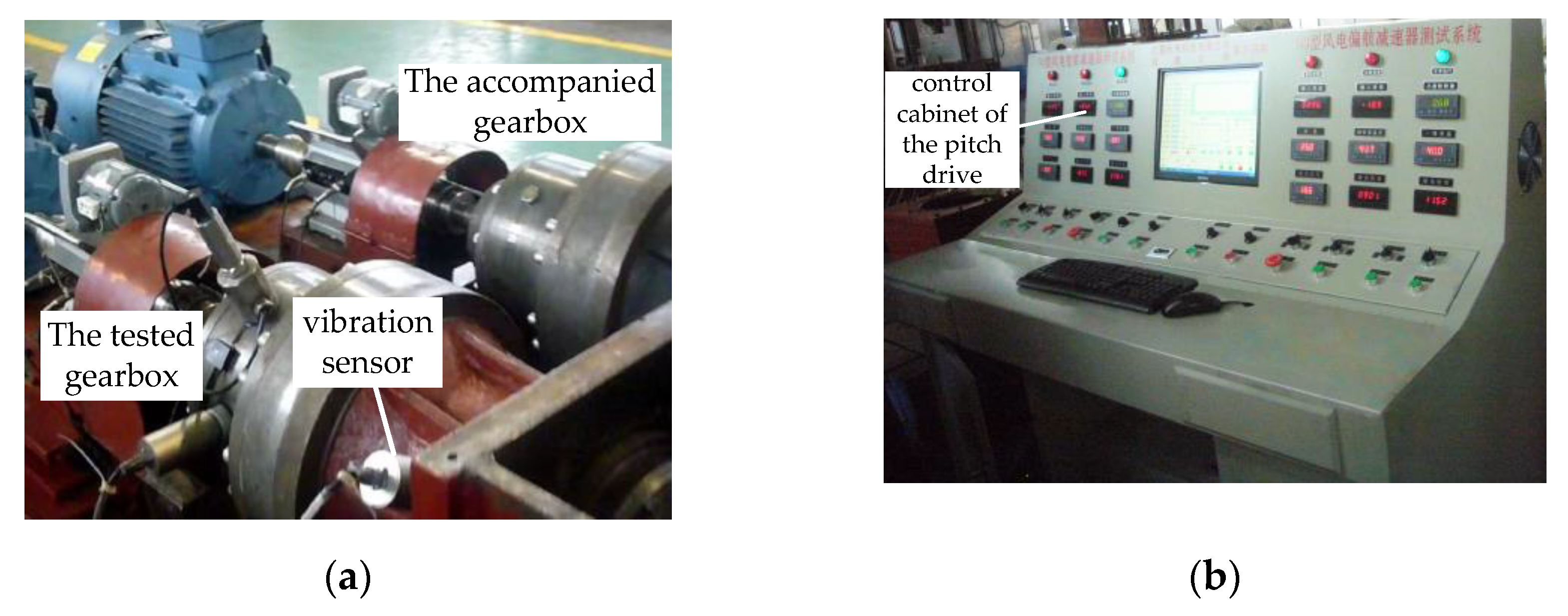
A test rig is built to measure the dynamics behavior of the pitch drive of 2 MW wind turbines. The structure of the pitch drive is shown in Figure 13. Additionally, as shown in Figure 14a, the tested pitch drive connects with an accompanied gearbox through an idle gear with the input speed 1600 r/min and input power 6.4 KW. The power is supplied by a direct current motor equipped with electronic speed control, and then transmitted to the tested gearbox, idler and the accompanied gearbox. The rotational speed decreases through the tested gearbox and then increases through the accompanied gearbox. A torque speed sensor is installed between the motor and gearbox.
Furthermore, a uniaxial vibration sensor is mounted on the output shaft housing of the tested gearbox through magnetic attraction. The vibration sensor is Vib 90 with a 1000 Hz frequency response; it tests the radial acceleration signal of the output shaft. A signal processor inside the vibration sensor can calculate the velocity and displacement according to the vibration signal automatically, and then output the vibration data in the time domain. In addition, a data acquisition card is installed in the control cabinet. All the data are collected using LabView software and then displayed on the screen of the control cabinet, as shown in Figure 14b. Moreover, the vibration displacements of the gearbox are tested under three types of load: 50% rated torque, 100% rated torque and 150% rated torque.
4.2. Experimental Results
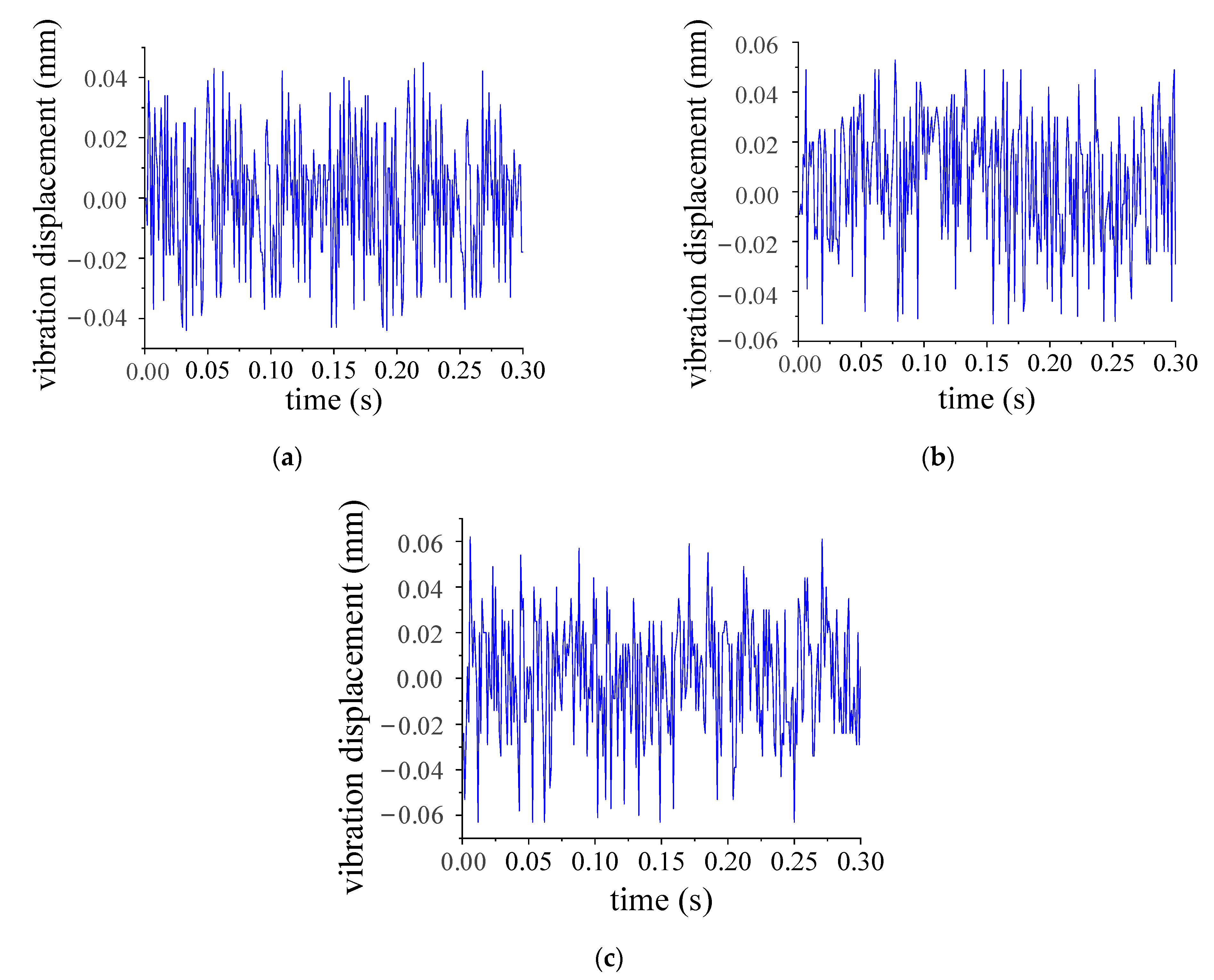
Since the carrier in the third stage is connected to the output shaft, their displacements are similar. Thus, the displacement of the carrier in the third stage is replaced by that of the output shaft. The vibration displacements of the carrier in the third stage under 50%, 100% and 150% torque are shown in Figure 15a–c, respectively. The amplitude of the vibration displacement under 50% load is 0.043 mm, and the peak-to-peak displacement is 0.085 mm. Moreover, the amplitude of the vibration displacement with 100% load is 0.054 mm, and the peak-to-peak displacement is 0.105 mm. While the amplitude and the peak-to-peak displacement of the displacement for the carrier with 150% load are 0.063 mm and 0.121 mm, respectively.
4.3. Comparison with Experimental Results
Table 5 shows the comparison between the tested displacement and theoretical vertical displacement Yc3 of the carrier in the third stage, which is shown in Figure 8c and Figure 9a,b. Both the amplitude and peak-to-peak displacement of the theoretical displacement are close to those of the tested displacement. The experimental results generally agree with the theoretical results. The slight difference between the experiment and theoretical results may be because the magnetic attraction installation brings a small error. The effectiveness of the dynamic load sharing model for the pitch drive for MW wind turbines is validated.
5. Conclusions
This study investigates the load sharing of the pitch drive for MW wind energy systems, illustrates the dynamic load sharing model, and obtains the dynamic load sharing coefficients of all stages. Afterwards, the displacement calculated in this model is verified by an experiment, and the theoretical model is effective. Conclusions are achieved as follows:
1.
The load sharing coefficient of external meshing in the first stage is the largest. Thus, the load distribution is most uneven in the first stage.
2.
The effect of the external and internal meshing stiffness for all stages is studied with the basic parameters of the pitch drive of 2 MW wind turbines. There is saltation of the load sharing coefficient with the improvement in the meshing stiffness. Therefore, the meshing stiffness in the saltation areas should be avoided in the design process.
3.
Furthermore, eccentric errors for the sun gear, carrier, ring gear and planetary gear on the load sharing behavior are analyzed in this paper. The load sharing coefficients of both internal and external meshing augment greatly with the increment of eccentric errors of the planetary gear and carrier. Therefore, these two errors should be controlled.
4.
The tooth frequency error of the external/internal meshing bears a main impact on the corresponding load sharing coefficient.
5.
The displacement of the dynamic load sharing model for the pitch drive in MW wind turbines is validated by the vibration experiment under the 50%, 100% and 150% rated torque in a test rig.
Lastly, these conclusions can provide a theoretical reference in designing high-performance planetary gear systems.
Author Contributions
Conceptualization, C.H.; methodology, C.H.; software, T.Y.; validation, S.Y.; formal analysis, T.Y.; investigation, S.Y.; resources, X.L.; data curation, Y.H.; writing—original draft preparation, T.Y..; writing—review and editing, X.L.; visualization, Y.H; supervision, X.L.; project administration, X.L.; funding acquisition, C.H. All authors have read and agreed to the published version of the manuscript.
Funding
This research was funded by the National Natural Science Foundation of China, grant number 51705442 and 12104386; the China Scholarship Council, grant number 201908430286; the Construction Project of National Independent Innovation Demonstration Area of Xiangtan, grant number GX-YB20211018; and the Science and Technology Innovation Program of Hunan Province, grant number 2021RC2097.
Data Availability Statement
The data presented in this study are available on request from the corresponding author. The data are not publicly available due to intellectual property protection.
Acknowledgments
We are grateful to the referees whose comments were helpful in the revision of this paper. The sojourn of the first author as a visiting scholar at Rice University in Houston, USA is acknowledged with pleasure.
Conflicts of Interest
The authors declare no conflict of interest.
References
Kahraman, A. Load Sharing Characteristics of Planetary Transmissions. Mech. Mach. Theory1994, 29, 1151–1165. [Google Scholar] [CrossRef]
Iglesias, M.; Fernandez, A.; Dejuan, A. Planet position errors in planetary transmission: Effect on load sharing and transmission error. Front. Mech. Eng.2013, 8, 80–87. [Google Scholar] [CrossRef]
Iglesias, M.; Fernandez, A.; Dejuan, A. Planet Eccentricity Error on a Planetary Gear Transmission: Influence on Load Sharing. Mech. Mach. Sci.2015, 21, 1381–1390. [Google Scholar]
Iglesias, M.; Fernandez, A.; Dejuan, A. Planetary transmission load sharing: Manufacturing errors and system configuration study. Mech. Mach. Sci.2017, 11, 21–38. [Google Scholar] [CrossRef]
Xu, Z.; Yu, W.; Shao, Y.; Yang, X.; Nie, C.; Peng, D. Dynamic modeling of the planetary gear set considering the effects of positioning errors on the meshing position and the corner contact. Nonlinear Dyn.2022, 109, 1551–1569. [Google Scholar] [CrossRef]
Ryali, L.; Talbot, D. A dynamic load distribution model of planetary gear sets. Mech. Mach. Theory2021, 158, 104229. [Google Scholar] [CrossRef]
Kim, J.G.; Park, Y.J.; Lee, G.H.; Lee, S.T.; Oh, J.Y. Experimental Study on the Carrier Pinhole Position Error Affecting Dynamic Load Sharing of Planetary Gearboxes. Int. J. Precis. Eng. Manuf.2018, 19, 881–887. [Google Scholar] [CrossRef]
Kim, J.G.; Park, Y.J.; Lee, S.D.; Oh, J.Y.; Kim, J.H.; Lee, G.H. Influence of the Carrier Pinhole Position Errors on the Load Sharing of a Planetary Gear Train. Int. J. Precis. Eng. Manuf.2018, 19, 537–543. [Google Scholar] [CrossRef]
Wang, J.; Yang, S.; Liu, Y.; Mo, R. Analysis of Load-Sharing Behavior of the Multistage Planetary Gear Train Used in Wind Generators: Effects of Random Wind Load. Appl. Sci.2019, 9, 5501. [Google Scholar] [CrossRef]
Theling, J.; Brimmers, J.; Brecher, C. Reducing mass while improving the operational behavior: Form optimization of planetary gearbox housings. Forsch. Im Ing.2021, 85, 543–551. [Google Scholar] [CrossRef]
Chung, W.-J.; Oh, J.-S.; Han, H.-W.; Kim, J.-T.; Park, Y.-J. Analytical study of floating effects on load sharing characteristics of planetary gearbox for off-road vehicle. Adv. Mech. Eng.2020, 12, 1687814020940468. [Google Scholar] [CrossRef]
Fan, Z.; Zhu, C.; Song, C. Dynamic Analysis of Planetary Gear system Considering the Flexibility of Internal Ring Gear. Iran. J. Sci. Technol. Trans. Mech. Eng.2020, 44, 695–706. [Google Scholar] [CrossRef]
Ryali, L.; Talbot, D. A dynamic gear load distribution model for epicyclic gear sets with a structurally compliant planet carrier. Mech. Mach. Theory2023, 181, 105225. [Google Scholar] [CrossRef]
Park, Y.J.; Lee, G.H.; Oh, J.S.; Shin, C.S.; Nam, J.S. Effects of Non-torque Loads and Carrier Pinhole Position Errors on Planet Load Sharing of Wind Turbine Gearbox. Int. J. Precis. Eng. Manuf. Green Technol.2019, 6, 281–292. [Google Scholar] [CrossRef]
Yoo, H.G.; Chung, W.J.; Kim, B.S.; Park, Y.J.; Kim, S.C.; Lee, G.H. Application of flexible pin for planetary gear set of wind turbine gearbox. Sci. Rep.2022, 12, 1713. [Google Scholar] [CrossRef] [PubMed]
Zhu, Z.; Zhu, R.; Bao, H.; Jin, G. Impact of run-out and meshing-frequency errors on dynamic load sharing for encased differential herringbone train. J. Aerosp. Power2011, 26, 2601–2609. [Google Scholar]
Chen, W.; Chen, S.; Hu, Z.; Tang, J.; Li, H. Dynamic analysis of a bevel gear system equipped with finite length squeeze film dampers for passive vibration control. Mech. Mach. Theory2020, 147, 103779. [Google Scholar] [CrossRef]
Zhu, Z.; Zhu, R.; Bao, H.; Jin, G. Analysis of dynamic floating displacement of center gear for encased differential planetary train. J. Cent. South Univ.2012, 43, 497–504. [Google Scholar]
Sun, Z.; Shen, Y.; Li, S. Study on dynamic behavior of encased differential gear train. Chin. J. Mech. Eng.2002, 38, 44–52. [Google Scholar] [CrossRef]
Figure 1.
The three dimension structure.
Figure 1.
The three dimension structure.
Figure 2.
The connection of the planetary gear system.
Figure 2.
The connection of the planetary gear system.
Figure 3.
The dynamics model of the planetary gear system in the jth stage.
Figure 3.
The dynamics model of the planetary gear system in the jth stage.
Figure 4.
The load sharing coefficients for the internal and external meshing in all stages. (a) External meshing in the first stage; (b) internal meshing in the first stage; (c) external meshing in the second stage; (d) internal meshing in the second stage; (e) external meshing in the third stage; (f) internal meshing in the third stage.
Figure 5.
Floating displacement of the sun gear. (a) The second stage; (b) the third stage.
Figure 5.
Floating displacement of the sun gear. (a) The second stage; (b) the third stage.
Figure 6.
The time domain response of some components in the first stage. (a) Rotational displacement up11 of the planetary gear; (b) rotational displacement up31 of the planetary gear; (c) radial displacement ηp31 of the planetary gear; (d) horizontal displacement Xc1 of the carrier.
Figure 6.
The time domain response of some components in the first stage. (a) Rotational displacement up11 of the planetary gear; (b) rotational displacement up31 of the planetary gear; (c) radial displacement ηp31 of the planetary gear; (d) horizontal displacement Xc1 of the carrier.
Figure 7.
The time domain response of some components in the second stage. (a) Rotational displacement up12; (b) rotational displacement up22; (c) radial displacement ηp22; (d) horizontal displacement Xc2 of the carrier.
Figure 7.
The time domain response of some components in the second stage. (a) Rotational displacement up12; (b) rotational displacement up22; (c) radial displacement ηp22; (d) horizontal displacement Xc2 of the carrier.
Figure 8.
The time domain response of some components in the third stage. (a) Horizontal displacement Hs3; (b) rotation displacement up33; (c) vertical displacement Yc3 of the carrier; (d) rotation displacement uc3 of the carrier.
Figure 8.
The time domain response of some components in the third stage. (a) Horizontal displacement Hs3; (b) rotation displacement up33; (c) vertical displacement Yc3 of the carrier; (d) rotation displacement uc3 of the carrier.
Figure 9.
The time domain response of the carrier in the third stage under different loads. (a) Vertical displacement Yc3 of the carrier under 50% load; (b) vertical displacement Yc3 of the carrier under 150% load.
Figure 9.
The time domain response of the carrier in the third stage under different loads. (a) Vertical displacement Yc3 of the carrier under 50% load; (b) vertical displacement Yc3 of the carrier under 150% load.
Figure 10.
The effect of the meshing stiffness on the dynamic load sharing coefficient. (a) External meshing stiffness in the first stage; (b) internal meshing stiffness in the first stage; (c) external meshing stiffness in the second stage; (d) internal meshing stiffness in the second stage; (e) external meshing stiffness in the third stage; (f) internal meshing stiffness in the third stage.
Figure 11.
The effect of the eccentric error on the load sharing coefficient. (a) Eccentric error of the sun gear; (b) eccentric error of the ring gear; (c) eccentric error of the planetary gear; (d) eccentric error of the carrier.
Figure 11.
The effect of the eccentric error on the load sharing coefficient. (a) Eccentric error of the sun gear; (b) eccentric error of the ring gear; (c) eccentric error of the planetary gear; (d) eccentric error of the carrier.
Figure 12.
The effect of the tooth frequency error on the load sharing coefficient. (a) The external meshing in the first stage; (b) the internal meshing in the first stage; (c) the external meshing in the second stage; (d) the internal meshing in the second stage; (e) the external meshing in the third stage; (f) the internal meshing in the third stage.
Figure 13.
The structure of the pitch drive.
Figure 13.
The structure of the pitch drive.
Figure 14.
The test rig of the pitch drive. (a) Test rig; (b) control cabinet.
Figure 14.
The test rig of the pitch drive. (a) Test rig; (b) control cabinet.
Figure 15.
The vibration displacement of the carrier in the third stage. (a) Vibration displacement at 50% load; (b) vibration displacement at 100% load; (c) vibration displacement at 150% load.
Figure 15.
The vibration displacement of the carrier in the third stage. (a) Vibration displacement at 50% load; (b) vibration displacement at 100% load; (c) vibration displacement at 150% load.
Table 1.
Manufacturing and assembling error for the components.
Table 1.
Manufacturing and assembling error for the components.
Part
Error
Symbol
Phase Angle
Sun gear
eccentric error
Esj
βsj
Planetary Gear
eccentric error
Epj
βpj
Carrier
planetary pin hole error
Ecj
βcj
Ring gear
eccentric error assembling error
Erj Arj
βrj γrj
Table 2.
Parameters of the pitch drive of a 2 MW wind turbine.
Table 2.
Parameters of the pitch drive of a 2 MW wind turbine.
Parameters
First Stage
Second Stage
Third Stage
Sun gear tooth number
12
18
16
Planetary gear tooth number
30
28
23
Ring gear tooth number
75
75
65
Module
2.5
2.5
4
Mass of carrier (kg)
2.28
4.15
13.98
External meshing angle αw (°)
26.24
22.54
26.07
Internal meshing angle αn (°)
16.04
19.32
14.69
Input power P (kw)
6.4
Input speed ns (r/min)
1600
220.7
42.7
Table 3.
Stiffnesses for all stages (N/m).
Table 3.
Stiffnesses for all stages (N/m).
Parameters
First Stage
Second Stage
Third Stage
Carrier support stiffness
1.5 × 10⁹
1.52 × 10⁹
1.7 × 10⁹
Carrier rotational stiffness
1.3 × 10⁹
1.32 × 10⁹
1.41 × 10⁹
Average external meshing stiffness
8.16 × 10⁸
2.09 × 10⁹
3.17 × 10⁹
Average internal meshing stiffness
1.11 × 10⁹
2.52 × 10⁹
3.91 × 10⁹
Table 4.
The errors of the transmission component in the pitch drive.
Table 4.
The errors of the transmission component in the pitch drive.
Error
First Stage (μm)
Second Stage (μm)
Third Stage (μm)
Es
(17, 0°)
(17, 0°)
(22, 0°)
Epi
(21, 0°) (21, 120°) (21, 240°)
(21, 0°) (21, 120°) (21, 240°)
(21, 0°) (21, 120°) (21, 240°)
EI
(40, 0°)
(40, 0°)
(41, 0°)
Ec
(25, 0°)
(25, 0°)
(25, 0°)
AI
(20, 0°)
(20, 0°)
(30, 0°)
εspi
15
15
15
εpiI
20
20
20
Table 5.
Comparison between the analytical and test vibration of the carrier in the third stage.
Table 5.
Comparison between the analytical and test vibration of the carrier in the third stage.
Displacement
Method
50% Torque
100% Torque
150% Torque
Amplitude (mm)
analytical
0.039
0.051
0.061
test
0.043
0.054
0.063
Peak-to-peak displacement (mm)
analytical
0.078
0.097
0.116
test
0.085
0.105
0.121
Disclaimer/Publisher’s Note: The statements, opinions and data contained in all publications are solely those of the individual author(s) and contributor(s) and not of MDPI and/or the editor(s). MDPI and/or the editor(s) disclaim responsibility for any injury to people or property resulting from any ideas, methods, instructions or products referred to in the content.
Hu, C.; Yuan, T.; Yang, S.; Hu, Y.; Liang, X.
Dynamic Load Sharing Behavior for the Pitch Drive in MW Wind Turbines. Processes2023, 11, 544.
https://doi.org/10.3390/pr11020544
AMA Style
Hu C, Yuan T, Yang S, Hu Y, Liang X.
Dynamic Load Sharing Behavior for the Pitch Drive in MW Wind Turbines. Processes. 2023; 11(2):544.
https://doi.org/10.3390/pr11020544
Chicago/Turabian Style
Hu, Congfang, Tao Yuan, Shiping Yang, Yunbo Hu, and Xiao Liang.
2023. "Dynamic Load Sharing Behavior for the Pitch Drive in MW Wind Turbines" Processes 11, no. 2: 544.
https://doi.org/10.3390/pr11020544
Note that from the first issue of 2016, this journal uses article numbers instead of page numbers. See further details here.
Article Metrics
No
No
Article Access Statistics
For more information on the journal statistics, click here.
Multiple requests from the same IP address are counted as one view.
Hu, C.; Yuan, T.; Yang, S.; Hu, Y.; Liang, X.
Dynamic Load Sharing Behavior for the Pitch Drive in MW Wind Turbines. Processes2023, 11, 544.
https://doi.org/10.3390/pr11020544
AMA Style
Hu C, Yuan T, Yang S, Hu Y, Liang X.
Dynamic Load Sharing Behavior for the Pitch Drive in MW Wind Turbines. Processes. 2023; 11(2):544.
https://doi.org/10.3390/pr11020544
Chicago/Turabian Style
Hu, Congfang, Tao Yuan, Shiping Yang, Yunbo Hu, and Xiao Liang.
2023. "Dynamic Load Sharing Behavior for the Pitch Drive in MW Wind Turbines" Processes 11, no. 2: 544.
https://doi.org/10.3390/pr11020544
Note that from the first issue of 2016, this journal uses article numbers instead of page numbers. See further details here.


