Article

Study on the Shadow Effect of the Stress Field around a Deep-Hole Hydraulic-Fracturing Top-Cutting Borehole and Process Optimization

1
School of Mining Engineering, Xi’an University of Science and Technology, Xi’an 710054, China
2
Safety Branch, China Coal Research Institute, Beijing 100013, China
3
School of Energy and Mining Engineering, China University of Mining Science and Technology (Beijing), Beijing 100083, China
*
Author to whom correspondence should be addressed.
Processes 2023, 11(2), 367; https://doi.org/10.3390/pr11020367
Submission received: 15 December 2022 / Revised: 6 January 2023 / Accepted: 10 January 2023 / Published: 24 January 2023
(This article belongs to the Special Issue Process Safety in Coal Mining)

Abstract

:
The clean utilization and green development of coal resources have become a research focus in recent years. Underground hydraulic fracturing technology in coal mines has been widely used in roof pressure relief, top coal pre-splitting, gas drainage, roadway pressure relief and goaf disaster prevention. Different in situ stress types cause great differences in the stress field around the boreholes, the critical pressure of the fracture initiation, and the direction of the fracture expansion trend; in addition, the stress shadow effect generated by the superposition of stress fields between boreholes relatively close together has a mutual coupling effect on the evolution of the stress field, the development of the plastic zone, and the crack propagation of the rock mass. Therefore, an effective method to solve the problem is to establish a mechanical model of hydraulic fracturing in boreholes for theoretical calculation, determine the influence mechanism of the crack shadow effect, and design a numerical simulation experiment of the equivalent stress fluid–solid coupling of hydraulic fracturing under different pore diameters and spacings. In addition, combining rock mechanics and fracture mechanics to analyze the influence of the shadow effect of the stress field between cracks on the evolution of the equivalent stress and the plastic zone is one of the important advances in this paper. Considering the engineering background of the site, the geological conditions and the requirements of general regulations, it is considered that the parameter selection of roof fracturing hydraulic fracturing technology in the Yushen mining area is more suitable when 0.12 m hole diameter and 3.5 m hole spacing are selected.

1. Introduction

In recent years, the research into the fluid–solid coupling of hydraulic fracturing has attracted the attention of experts and scholars in many fields around the world. In 1925, Terzaghi [1] regarded the consolidation of deformable saturated porous media as a coupling problem of flow boundary–solid boundary deformation. On the basis that the flow field satisfied Darcy’s law, taking the total stress and pore fluid pressure of the saturated rock and soil as the state variables, a relatively complete three-dimensional consolidation theory was established. Barenblatt [2,3] (1959) introduced the definition of the field near the crack boundary and analyzed the linear elasticity by using the relevant provisions and assumptions in elasticity.
Therefore, the rational development of some resources with special mining difficulties in the past two decades has also become the global focus of scientific mining researchers. The research and development of safe and effective mining technology for near-vertical coal seams, deep high-thermal coal seams, short-distance thin coal seams, and deep strong-impact-prone coal seams has entered a new stage. In the 1990s, the hydraulic fracturing process carried out by the American Petroleum System for shale gas development and oil penetration and production was introduced into the mining industry and successfully applied to the seam cutting of the hard roof plate of the mine, the pressure relief of the roadway, and the treatment of the weakening of the top coal. In order to determine that the layout plan of the prescribed hydraulic-fracturing (PHF) boreholes can ensure that the fractures can be successfully expanded and the roof can be cut without premature penetration leading to early pressure reduction, it is important and difficult to reasonably design the spacing of the hydraulic-fracturing boreholes.
On this basis, Hutchinson [4], Sneddon [5], Green [6], Warpinski et al. [7], Wang [8], and Nagel et al. [9] have made some progress in determining the spatial distribution characteristics of stress shadowing. Considering the effects of crack spacing, rock mechanics parameters, and in situ stress in three-dimensional conditions, it was found that the influence range of the increase in the minimum horizontal stress was large and extended in the direction of the crack height, but it had little effect on the crack tip region. Zhao et al. [10] studied the three-dimensional propagation mechanism of the hydraulic fracture in a borehole with multiple angles and different spacings in a three-dimensional rock mass and concluded that the increase in the intermediate principal stress suppressed the propagation of the fracture perpendicular to the direction of the intermediate principal stress; the propagation track of the crack in the direction of the intermediate principal stress became straighter. The change in the intermediate principal stress did not change the main direction of the crack propagation (the direction of the maximum principal stress).
In terms of the development of multi-physical field numerical simulation experimental software, in the past two decades, scholars at home and abroad have mainly carried out engineering scale research on the basis of binary numerical models to explore the law of interaction between porous hydraulic fracturing and fracture propagation. Wang [11], Liu et al. [12], and Michael [13] found in experiments that when designing the perforation spacing and aperture, the stress shadow effect could be weakened by reasonably optimizing the setting of large or nonuniform perforation spacing, so as to make the spatial morphology of the hydraulic fracture propagation more uniform.
To summarize, it is of new significance to study the influence of the borehole size and borehole spacing on the shadow effect between the hydraulic fracturing fractures within the three-dimensional rock mass scale model. Building a three-dimensional mechanical model and grid division of three-dimensional multi-cluster perforated rock materials can more realistically simulate the propagation of fracturing fractures in order to then design the reasonable arrangement of hole spacing and aperture, so that the spatial form of fracture propagation is more conducive to engineering applications. It has been planned to obtain the optimal parameters applicable to roof hydraulic fracturing drilling in the Yushen mining area under the influence of special conditions, such as shadow effect, by means of mechanical model establishment, theoretical calculation and analysis, multi physical field coupling numerical simulation experiments and mutual verification.

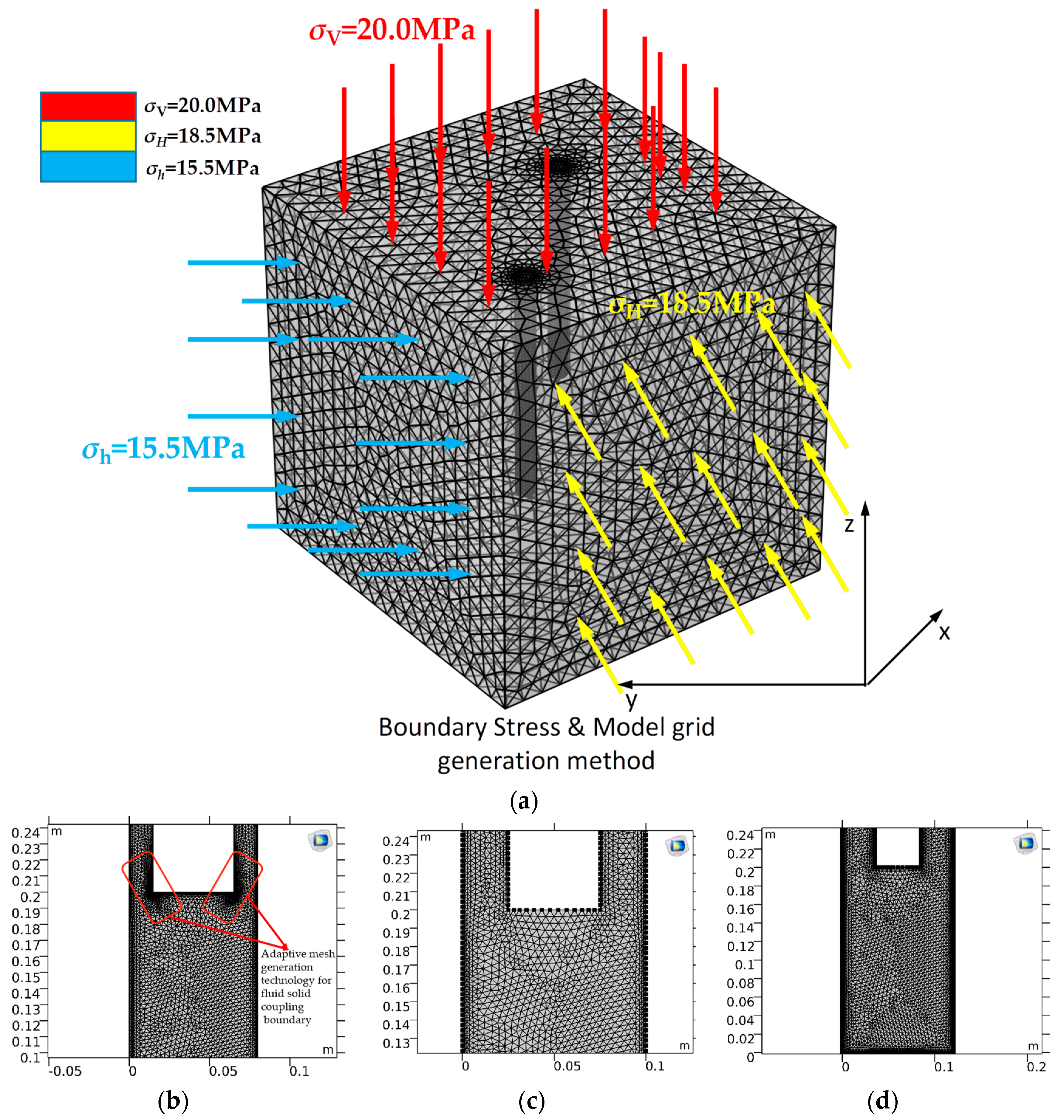
2. Simulation Engineering Background and Boundary Condition Setting

Geological Condition Background and Working Face Overview

Hydraulic fracturing and roof cutting are widely used to prevent rock burst or strong ground pressure in deep buried or deep mines from 400 m to 1000 m. With the increase in the buried depth and the change in the importance of the tectonic stress in the in situ stress of the unit coal body, the type of in situ stress changes, as shown in Figure 1a. Therefore, the research background of the shadow effect of deep-hole hydraulic-fracturing jet-fracturing boreholes was set as the type III geostress type with vertical stress as the maximum principal stress, as shown in Figure 1e; in the absence of cutting-induced fractures and the influence of the stress shadow effect between adjacent boreholes, the dominant trend of fracture space expansion gradually moves to the minimum horizontal principal stress σ3 direction deflection. In most cases, deep-hole hydraulic fracturing is conducted from the leading position of the roadway to the hard roof above the stope, see Figure 1b. The overall development trend of fracturing fractures is perpendicular to the advancing direction of the working face and along the vertical stress direction. This fracture development mode has natural advantages for cutting the hard roof along the mining fracture direction, shortening the fracture step, and weakening the leading support pressure of the stope. Therefore, it is particularly important to reasonably optimize the spacing and aperture of the boreholes to reduce the disturbance of the stress shadow effect on the crack propagation and to avoid the influence of water leakage from the adjacent boreholes on the effect of roof cutting.
We selected the geological conditions in the Xiangning mining area of Hedong Coalfield, Shanxi Province, where the buried depth of the coal seam was 555 m~631 m, which was the Shennan’ao coal mine. In order to facilitate a unified calculation, the buried depth parameter was determined to be 600 m, the working face length was 180 m, and the advancing length was 1286 m. The hard sandstone on the roof was treated to weaken the rock pressure and high-energy dynamic load test pieces, and the multilayer mudstone and fine sandstone on the roof were subject to hydraulic fracturing.
As shown in Figure 1c–e, there were three distinct development stages in the spatial form of hydraulic-fracturing fracture propagation under different in situ stress types: 1. the crack initiation stage along the prefabricated fracture or the jet nozzle; 2. the deflection stage dominated by the ground stress; and 3. the continuous expansion along the direction of the maximum principal stress and perpendicular to the direction of the minimum principal stress.
An excessive size of a three-dimensional fluid–structure coupling experimental model leads to non-convergence; however, too small a size makes it difficult to meet the actual rock-block size at the field. Considering this, a similar model of a normal-cube rock mass with a side length of 10 m was established. The boundary conditions were selected to assign parameters to the model through the measured in situ stress state of the basic roof rock in the Xiangning mining area; by comparing the convergence effects of three adaptive mesh generation methods (coarsening, thinning, and refining), it was determined that the refined mesh better considered the above experimental purposes.
The experimental scheme of borehole spacings of 3 m, 3.5 m, and 4 m was intended to further study the common situation of the borehole spacing for hydraulic fracturing in coal mines in “Detailed rules for prevention and control of rock burst in coal mines” published by the Ministry of Coal Industry of the People’s Republic of China.
The pore diameters of the high-pressure fracturing drills were taken to be 0.08 m, 0.10 m, and 0.12 m, which were designed according to the three most commonly used boreholes for hydraulic fracturing in coal mines.
Based on the above two considerations, an experimental scheme was designed for the research object of this manuscript: first, the scheme most suitable for the studied engineering background geological conditions was selected by comparing the fluid–structure coupling boundary surface stress and flow velocity of three different hole diameters; then, the influence of the stress shadow effect on the fracturing effect under 3.0 m, 3.5 m, and 4.0 m hole spacing was compared on the basis of this aperture.
Due to the self-adaptive mesh generation function developed in the multi-physical field coupling numerical simulation software COMSOL 5.6, the mesh at the boundary of the borehole wall of the hydraulic fracturing jet could automatically adapt to the transition state of laminar flow and turbulence, better converge the calculation of the surface velocity and the equivalent stress at the fluid–solid coupling boundary in the turbulent state, where the internal flow velocity exceeded 2300 Reynolds number, and densify and set smooth grids at fewer positions at the borehole wall boundary, as shown in Figure 2. In the practical application of underground hydraulic-fracturing engineering in coal mines, the most common drill pipe sizes are 0.08, 0.10, and 0.12 m. These three sizes of drill pipes can simultaneously meet the rapid and high-pressure passage of the large-flow fracturing fluid and have no destructive impact on the coal pillar in the cross roadway. Three drilling sizes with different diameters of 0.08 m, 0.1 m, and 0.12 m were set, with a hole depth of 3 m, 5 m, and 8 m (5% of different hole spacings) × five × 5 m sandstone-rock material test block. The density was ρ 2460 kg/m3; the Young’s modulus E was 4.2 Gpa; Poisson’s ratio was μ 0.75; the vertical stress σV was 20 Mpa; the horizontal maximum principal stress σH was 18.5 Mpa; and the horizontal minimum principal stress σh was 15.5 Mpa. First, we determined the optimal aperture; then, we conducted the stress shadow effect experiment under a fixed aperture size.
In the fluid solid coupling simulation experiment, for the fluid mechanics calculation part, the water inlet (the starting point of the fracturing fluid inflow), the wall (the part where the fluid contacts the solid) and the water outlet (the end point of the fracturing fluid outflow) are usually set. The water outlet is free in the jet stage, closed in the fracturing stage, and the model is pressurized.
Figure 1b shows the development trend of fracture propagation direction induced by different geostress types, while Figure 2 shows the experimental model to be consistent with the standard specimen of rock mechanics experiment in the laboratory and the drilling hole layout.
The flow field inside the borehole was determined by the inlet flow velocity, outlet pressure, and wall equation, where the inlet flow velocity was 3 × 10² m/s, the outlet was open and free, and the orifice pressure was 0 Pa. The flow field wall was smooth without sliding. The total pressure of the internal flow field was 35 Mpa under the pressure holding state.
Considering that the COMSOL multi physical field simulation software is based on the calculation principle developed by finite element method, the excellent simulation on the boundary of the two physical fields and the relatively accurate calculation of the corresponding stress field and velocity field are highlighted when the hydraulic fracturing process is simulated. However, there is also a defect that the fracture expansion cannot be visualized. Therefore, this manuscript illustrates the scientific problems of the research object by comparing its equivalent force field and surface velocity field, and looks forward to fitting the reflection of crack propagation mode in the laboratory with the simulation results in this manuscript in the future research work.
In consideration of both convergence and experimental effect, it is considered that the finer adaptive mesh generation method is most suitable for the experimental study of fluid structure coupling mechanical model established in this manuscript.
Based on the above boundary conditions and the multi-physical field fluid–solid coupling parameter settings, the mesh division and model size are shown in Figure 2.
The turbulent governing equation of the transient solver inside the borehole was as follows:
ρ u t + ρ ( u ) u = [ p I + κ ] + F ρ u = 0
κ = ( μ + μ T ) ( u 2 + ( u 2 ) T )
ρ k t + ρ ( u ) K = [ ( μ + μ T σ K ) K ] + P k ρ ε
ρ ε t + ρ ( u ) ε = [ ( μ + μ T σ ε ) ε ] + C ε 1 ε k 2 P k C ε 2 ρ ε 2 k 2 ε = e p
μ T = ρ C μ k 2 ε , P k = μ T [ u : ( u + ( u ) T ) ]
where u is the velocity field component, m/s; P is the pressure, MPa; F is the boundary pressure of the solid mechanics, MPa; K (K is an capital English letter) is the turbulent flow energy N·m; ε is the turbulent dissipation rate; ρ is the fluid density, kg·m3; ▽ is the symbol of the nabrakin operator; κ (kappa ‘κ’ is a Greek alphabet) is the directional gradient matrix, μ is the dynamic viscosity coefficient, n·s/m3; Cεl is the compressibility of the fluid; here, the incompressible flow was selected, and the parameter was 1; and k (k is an italic lowercase English letter) is the turbulence auxiliary variable constant.
The solid boundary coupling governing equation is:
ρ 2 u t 2 = s + F V
where s is the displacement of the solid boundary, m; and FV is the normal stress at the solid boundary, MPa.

3. Internal Flow Field and Boundary Surface Pressure of Solid Mechanics in Different Boreholes

Based on the above flow-field transient control equations and solid-mechanics boundary equations, the transient solver was used to solve them. The borehole surface velocity and fluid pressure obtained after convergence and equilibrium are shown in Figure 3, Figure 4 and Figure 5.
According to the analysis of the flow velocity–stress state of the inner wall of the 0.08 m borehole as shown in Figure 3, under the abovementioned computational fluid dynamics (CFD) flow-field parameter setting conditions, the peak flow velocity in the 0.08 m borehole reached about 1.47 Mach number, which met the turbulence state, and the peak velocity appeared at the slot position of the borehole wall. The peak pressure on the surface of the inner wall of the hole reached about 9 MPa, and the position of the peak pressure was basically the same as the position of the peak flow rate. This phenomenon indicated that the crack initiation position of the 0.08 m hole was more likely to occur at the wall of the hole but less likely to occur at the fracturing target rock layer at the bottom of the hole. Therefore, it is not recommended to select the 0.08 m hole for drilling and fracturing hard-rock layers under the working conditions assumed in this paper.
As shown in Figure 4, the flow velocity and boundary surface pressure of the internal flow field of the 0.10 m borehole were analyzed. The peak position of the flow velocity mainly occurred in the area between the jet nozzle and the bottom of the borehole. The peak flow velocity reached about 2 × 10² m/s. The peak position of the surface pressure also mainly appeared at the hole bottom, and the peak stress was about 10.2 MPa. Compared with the 0.08 m hole diameter, the peak flow velocity and peak pressure were reduced to some extent, but the flow velocity and pressure in the general area were increased, and the area of the peak position was also significantly increased, mainly at the bottom of the hole, which may weaken the roof by causing multiple cracks.
Figure 5 shows the internal flow velocity and fluid–solid coupling boundary pressure state of the 0.12 m borehole. When the 0.12 m borehole was selected for hydraulic fracturing, the peak flow velocity reached 1.4 × 10² m/s, which was widely distributed at the slit between the hole bottom, the hole orifice, and the hole wall. The surface peak pressure was about 7 MPa, which was distributed throughout the hole wall. Through comprehensive analysis of Figure 3, Figure 4 and Figure 5, with the gradual increase in the borehole diameter, the peak flow velocity and peak surface pressure of the flow field weakened to a certain extent but remained on the same order of magnitude as a whole, while the distribution of the peak area increased significantly, which was not advantageous for the pressure of hard but thin rock layers. However, during the fracturing operation of hard roof plates in deep mines, the target fracturing rock layers are generally thicker basic roof layers. Therefore, in these three schemes, the selection of the 0.12 m borehole diameter for the next step of the stress-shadow effect experiment comparison is of more practical significance for the fracturing optimization under the hypothetical conditions in this paper. When the borehole spacing is small, a stress shadow effect appears, and the influence range of the plastic zone overlaps, resulting in the rock between the boreholes being relatively broken, and the stress in the plastic zone decreases. When the two boreholes move further away, the cracks around the boreholes are developed and connected, but the stress shadow effect does not appear; hence, the stress field value between the boreholes increases.

4. Contrast Experiment of the Stress Shadow Effect between Different Borehole Spacings

The study of the stress shadow effect between natural primary cracks or artificial cracks was initially carried out for fractures created during shale gas extraction [14,15]; in Yu et al. [16], an analytical equation was given for the redistribution of the induced stress components between the stress shadows [17,18,19]:
Δ σ x x , i n d u c e d = A c A c ( σ x x , i n d u c e d l 1 2 + σ y y , i n d u c e d m 1 2 + 2 τ x y , i n d u c e d l 1 2 m 1 2 ) d x 2 A c Δ σ y y , i n d u c e d = A c A c ( σ x x , i n d u c e d l 2 2 + σ y y , i n d u c e d m 2 2 + 2 τ x y , i n d u c e d l 2 2 m 2 2 ) d x 2 A c
where x is the average induced stress along the tangent direction and normal direction of the crack, Ac is the half length of the crack, taken as 0.5 m; mi is the distance between end cracks, m; li is the crack width, m; σyy,induced, σxx,induced, τxy,induced is the stress tensor, respectively, MPa; Δσyy,induced, Δσxx,induced, Δτxy,induced is the increment in the stress tensor, respectively, MPa [20,21,22,23].
Figure 6a,b shows the influence range of the von Mises equivalent stress in the rock mass caused by 0.12 m borehole fracturing with 3.0 m spacing; Figure 6c,d shows the influence range of the von Mises equivalent stress in the rock mass caused by 0.12 m borehole fracturing with 3.5 m spacing, and Figure 6e,f shows the influence range of the von Mises equivalent stress in the rock mass caused by 0.12 m borehole fracturing with 4.0 m spacing. Through comparative analysis, with the increase in the borehole spacing, the damage range around the borehole also increased, especially the damage range at the orifice, and the overall average value of the equivalent stress around the borehole also increased at the spacing of 4.0 m. Therefore, in order to avoid the influence of the stress shadow effect on the spatial shape of the fracture development and the expansion and the pressure relief in advancing during the actual hydraulic-fracturing rock-breaking construction, it is necessary to ensure that the influence range of the equivalent stress of the fracture is at the overlapping critical edge as far as possible.
With the increase in the buried depth, the spatial shape trend of the fracture surface development and the expansion of the hydraulic-fracturing borehole wall changes significantly. Under the condition of shallow-buried in situ stress, where the horizontal maximum principal stress is the maximum principal stress, and the vertical stress is the minimum principal stress, the fracture surface tends to expand along the water square direction to weaken the thickness of the fractured rock stratum. Under the in situ stress condition of deep mines, where the vertical stress is the maximum principal stress, and the horizontal stress is the minimum principal stress, the fracture plane tends to shorten the fracture step of the fractured rock layer along the vertical direction. Therefore, it was concluded that under different in situ stress types and different purposes of cutting hard-rock layers, appropriate drilling orientations and induction methods should be selected to optimize and control the spatial morphology of the fracture plane.

5. Discussion and Conclusions

Based on the established rock-mechanics multi-physical field fluid–solid coupling hydraulic-fracturing mechanical model and the assumptions and boundary conditions in computational fluid mechanics and rock mechanics, the turbulent control equation of the internal flow field in the borehole, the boundary laminar-flow control equation, and the fluid–solid coupling boundary conditions were obtained, and the rock-mass model borehole surface was substituted as the load boundary condition to simulate the impact of the stress shadow effect on the fracturing effect under different borehole spacings. At the same time, the borehole diameter and spacing suitable for the geological conditions of the example were compared.
In practice, the conclusions of this paper are the following:
  • Through the comparison of the fluid–solid coupling numerical simulation experiments, it was concluded that hydraulic fracturing is more effective for roof presplitting and pressure relief when the 0.12 m diameter borehole spacing is 3.5 m, considering the spatial development scale of the fracture network and fracturing efficiency (large-flow borehole).
  • The coupling relationship between the traditional hydraulic-fracturing fracture propagation model, the surface flow field velocity–stress model, and the solid material is difficult to express with the three-dimensional model. In view of the improvement of the above conditions, the displacement and stress constitutive relationship of the solid boundary were selected as appropriate functions to reconcile, and the boundary solution formula suitable for the three-dimensional shape of the borehole was obtained.
  • Further, deep-seated mechanism research should also be carried out on the flow field conditions of the cutting effect of the hydraulic fracturing technology on rock materials. The impact of the inlet flow velocity and pressure, outlet aperture, outlet pressure and flow, and the seepage state of the whole section of the borehole under the pressure-holding state on fracture propagation will be reflected in our further research.

Author Contributions

Conceptualization, S.W.; methodology, S.W.; software; J.L.; validation, S.W.; formal analysis, S.W.; investigation, S.W.; resources, S.W.; data curation, S.W.; writing—original draft preparation, S.W.; writing—review and editing, J.L.; visualization, J.L.; supervision, S.W.; project administration, S.W. All authors have read and agreed to the published version of the manuscript.

Funding

This research received no external funding.

Institutional Review Board Statement

Not applicable.

Informed Consent Statement

Informed consent was obtained from all subjects involved in the study.

Data Availability Statement

The experimental and analytical calculation data used to support the findings of this study are included within the article.

Conflicts of Interest

The authors declare that there are no conflicts of interest regarding the publication of this paper.

References

  1. Terzaghi, K.; Peck, R.B.; Mesri, G. Soil Mechanics in Engineering Practice; Wiley: New York, NY, USA, 1996. [Google Scholar]
  2. Barenblatt, G.I. The formation of equilibrium cracks during brittle fracture. General ideas and hypotheses. Axially-symmetric cracks. J. Appl. Math. Mech. 1959, 23, 622–636. [Google Scholar] [CrossRef]
  3. Barenblatt, G.I. Equilibrium cracks formed during brittle fracture rectilinear cracks in plane plates. J. Appl. Math. Mech. 1959, 23, 1009–1029. [Google Scholar] [CrossRef]
  4. Hutchinson, J.W. Singular behavior at the end of a tense crack in a hardening material. J. Mech. Phys. Solids 1968, 16, 13–31. [Google Scholar] [CrossRef]
  5. Sneddon, I.N.; Elliot, H.A. The opening of a Griffith crack under internal pressure. Q. Appl. Math. 1946, 4, 262–267. [Google Scholar] [CrossRef] [Green Version]
  6. Sneddon, I.N. The Distribution of Stress in the Neighbourhood of a Crack in an Elastic Solid. Proced. R. Soc. Lond. 1946, 187, 229–260. [Google Scholar]
  7. Warpinski, N.R.; Branagan, P.T. Alternate stress fracturing. J. Pet. Technol. 1989, 41, 990–997. [Google Scholar] [CrossRef]
  8. Wang, B.; Zhou, F.; Hu, J.; Gao, L.; Yuan, L.; Wang, Y. Fracture Interaction during Temporarily Plugging Staged Fracturing. J. Pet. Sci. Eng. 2018, 4, 8–13. [Google Scholar]
  9. Nagel, N.B.; Sanchez Nagel, M. Stress shadowing and microseismic events: A numerical evaluation. In Proceedings of the SPE Annual Technical Conference and Exhibition, Denver, CO, USA, 30 October–2 November 2011. [Google Scholar]
  10. Zhao, K.; Zhang, Z.; Li, W.; Wang, X.; Yi, K.; Sun, Z. Study on three-dimensional propagation of hydraulic fracture in borehole initiation based on xsite. J. Geotech. Eng. 2021, 43, 1483–1491. [Google Scholar]
  11. Wang, H. Poro-elasto-plastic modeling of complex hydraulic fracture propagation: Simultaneous multi-fracturing and producing well interference. Acta Mech. 2016, 227, 507–525. [Google Scholar] [CrossRef]
  12. Liu, C.; Li, M.; Hao, L.; Hu, H. Numerical simulation of hydraulic fracture propagation in heterogeneous unconventional reservoir. AIP Conf. Proc. 2017, 1890, 020010. [Google Scholar]
  13. Michael, A. Hydraulic Fracturing Optimization: Experimental Investigation of Multiple Fracture Growth Homogeneity via Perforation Cluster Distribution. Ph.D. Thesis, The University of Texas at Austin, Austin, TX, USA, 2016. [Google Scholar]
  14. Olson, J.E. Multi fracture propagation modeling: Applications to hydraulic fracture in shale and tight gas sands. In Proceedings of the 42nd American Rock Mechanics Association, San Francisco, CA, USA, 29 June–2 July 2008. [Google Scholar]
  15. Sepehri, J.; Solid, M.Y.; Morse, S.M. Application of extended finite elementmethod to simulate hydraulic fracture propagation from orientated performances. In Proceedings of the SPE Hydraulic Fracturing Technology Conference, The Woodlands, TX, USA, 3–5 February 2015. [Google Scholar]
  16. Yu, Y.J.; Zhu, W.C.; Li, L.C.; Wei, C.H.; Dai, F.; Liu, S.Y.; Wang, W.D. Theoretical analysis of stress shadow effect of mutual interference of hydraulic fracturing fractures. J. Rock Mech. Eng. 2017, 36, 2926–2939. [Google Scholar] [CrossRef]
  17. Zhang, Z.L.; Shu, C.; Khalid, M.S.U.; Chen, Z.; Yuan, Z.Y.; Liu, W. Investigations on the hydroelastic slamming of deformable wedges by using the smoothed particle element method. J. Fluids Struct. 2022, 114, 103732. [Google Scholar] [CrossRef]
  18. Long, T.; Zhang, Z.L.; Liu, M.B. A multi-resolution technique integrated with the smoothed particle element method (SPEM) for modeling fluid-structure interaction problems with free surfaces. Sci. China Phys. Mech. Astron. 2021, 64, 284711. [Google Scholar] [CrossRef]
  19. Wang, X.; Li, J.C.; Xiao, B.Z.; Yue, L. Propagation characteristics and prediction of blast-induced vibration on closely spaced rock tunnels. Tunn. Undergr. Space Technol. 2022, 123, 104416. [Google Scholar] [CrossRef]
  20. Abe, A.; Kim, T.W.; Horne, R.N. Laboratory hydraulic stimulation experiments to investigate the interaction between newly formed and preexisting fractures. Int. J. Rock Mech. Min. Sci. 2021, 141, 104665. [Google Scholar] [CrossRef]
  21. Li, B.; Zhang, J.; Liu, Y.; Qu, L.; Liu, Q.; Sun, Y.; Xu, G. Interfacial porosity model and modification mechanism of broken coal grouting: A theoretical and experimental study. Surf. Interfaces 2022, 33, 102286. [Google Scholar] [CrossRef]
  22. Zhang, J.; Li, B.; Liu, Y.; Li, P.; Fu, J.; Chen, L.; Ding, P. Dynamic multifield coupling model of gas drainage and a new remedy method for borehole leakage. Acta Geotech. 2022, 17, 4699–4715. [Google Scholar] [CrossRef]
  23. Li, B.; Shi, Z.; Li, L.; Zhang, J.; Huang, L.; He, Y. Simulation study on the deflection and expansion of hydraulic fractures in coal-rock complexes. Energy Rep. 2022, 8, 9958–9968. [Google Scholar] [CrossRef]
Figure 1. Relationship between the spatial development pattern of the deep-hole hydraulic-fracturing fractures and the evolution of the in situ stress types. (a) Comprehensive geological histogram. (b) The spatial relationship between the layout of the long-hole hydraulic-fracturing drilling site and the stope roof in the advance roadway (σV is the vertical maximum principal stress; σH is the maximum horizontal principal stress; and σh is the minimum horizontal principal stress); the red dotted line is the possible jet direction when the high-pressure water-jet drill pipe is used to induce the kerf. (c) Type I geostress. (d) Type Ⅱ geostress. (e) Type III geostress.
Processes 11 00367 g001aProcesses 11 00367 g001b
Figure 2. Boundary conditions and mesh generation. (a) Boundary load setting method of type I in situ stress rock specimen. (b) Grid of 0.08 m borehole. (c) Grid of 0.10 m borehole. (d) Grid of 0.12 m borehole.
Processes 11 00367 g002
Figure 3. Fluid–solid coupling boundary state of 0.08 m borehole. (a) Surface velocity of inner wall of 0.08 m borehole. (b) Surface velocity of inner wall of 0.08 m borehole (velocity peak position). (c) Hole wall pressure of 0.08 m hole diameter. (d) Hole wall pressure of 0.08 m hole diameter (stress peak position).
Processes 11 00367 g003aProcesses 11 00367 g003b
Figure 4. Fluid–solid coupling boundary state of 0.10 m borehole. (a) Surface velocity of inner wall of 0.10 m borehole. (b) Surface velocity of inner wall of 0.10 m borehole (velocity peak position). (c) Hole wall pressure of 0.10 m hole diameter. (d) Hole wall pressure of 0.10 m hole diameter (stress peak position).
Processes 11 00367 g004aProcesses 11 00367 g004b
Figure 5. Fluid–solid coupling boundary state of 0.12 m borehole. (a) Surface velocity of inner wall of 0.12 m borehole. (b) Surface velocity of inner wall of 0.12 m borehole (velocity peak position 1). (c) Surface velocity of inner wall of 0.12 m borehole (velocity peak position 2). (d) Hole wall pressure of 0.12 m hole diameter. (e) Hole wall pressure of 0.12 m hole diameter (stress peak position 1). (f) Hole wall pressure of 0.12 m hole diameter (stress peak position 2).
Processes 11 00367 g005
Figure 6. Stress shadow effect represented by an equal-effect stress field with different hole spacings. (a) Equivalent stress field of 0.12 m borehole with 3 m spacing. (b) Equivalent stress field of 0.12 m borehole with 3 m spacing (details). (c) Equivalent stress field of 0.12 m borehole with 3.5 m spacing. (d) Equivalent stress field of 0.12 m borehole with 3.5 m spacing (details). (e) Equivalent stress field of 0.12 m borehole with 4 m spacing. (f) Equivalent stress field of 0.12 m borehole with 4 m spacing (details).
Processes 11 00367 g006
Disclaimer/Publisher’s Note: The statements, opinions and data contained in all publications are solely those of the individual author(s) and contributor(s) and not of MDPI and/or the editor(s). MDPI and/or the editor(s) disclaim responsibility for any injury to people or property resulting from any ideas, methods, instructions or products referred to in the content.

