
Review of Methods for Diagnosing Faults in the Stators of BLDC Motors


Abstract
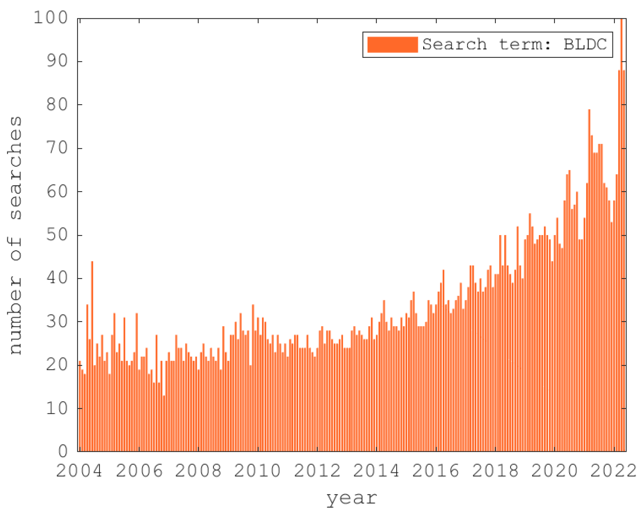
:1. Introduction
- A greater speed range due to non-dependence on the mechanical characteristics of the brushes;
- A better torque–speed characteristic due to the absence of friction produced by the brushes, which reduces the useful torque of the motor; in other words, a better capacity of heat dissipation that allows the generation of a higher torque;
- Better dynamic response due to the fact that the rotor has less inertia;
- Less noise due to the absence of discharges during the switching process;
- A smaller size, which widens its range of application.
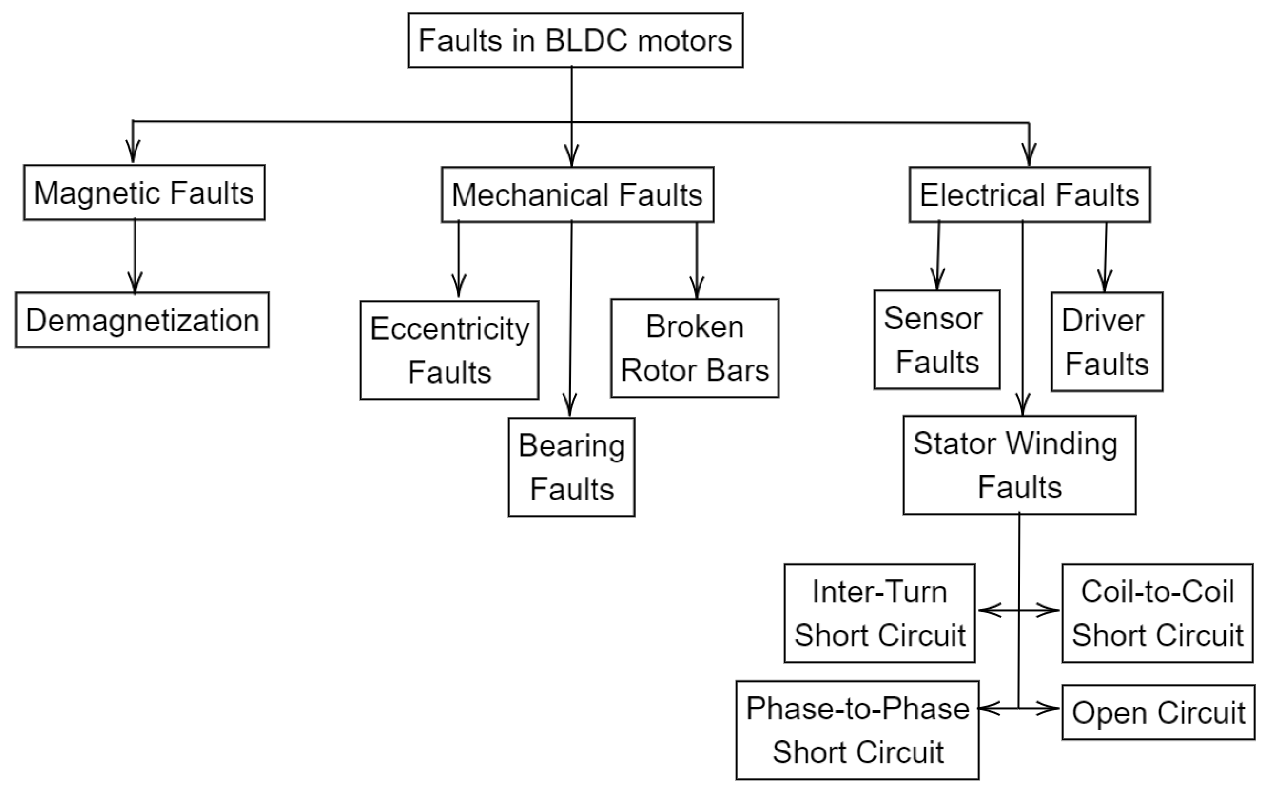
2. Faults in the Stator
2.1. Turn-to-Turn Short Circruit (Inter-Turn Fault)
2.2. Phase Coil-to-Coil Fault (Coil-to-Coil Fault)
2.3. Fault between Phases (Phase-to-Phase Fault)
2.4. Open-Circuit Fault of a Phase (Open-Circuit Fault)
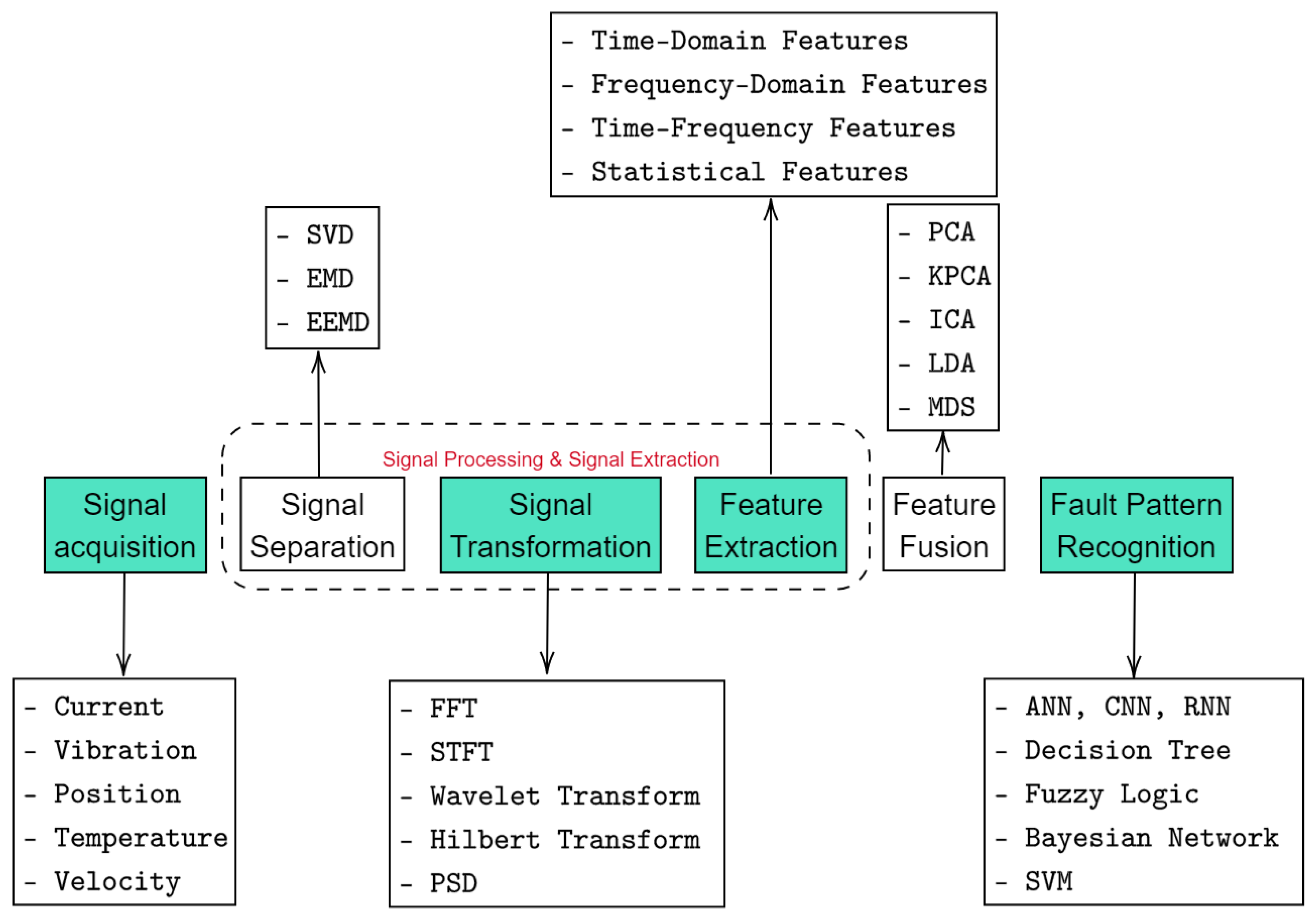
3. Classification of Methods for Diagnosing Faults in BLDC Motors
3.1. Signal-Based Methods
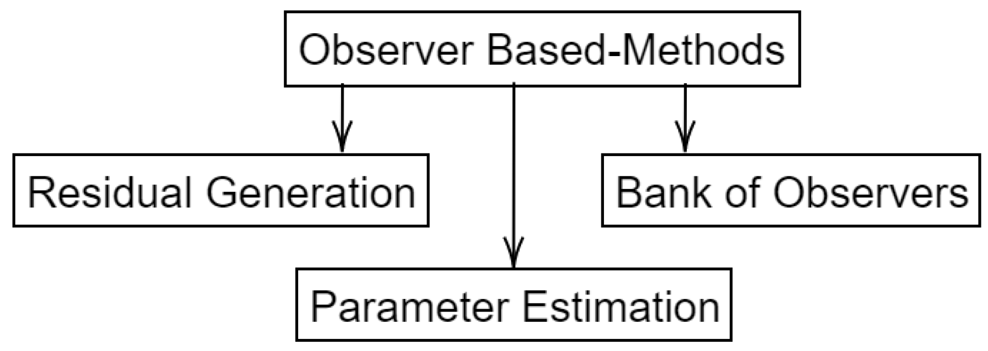
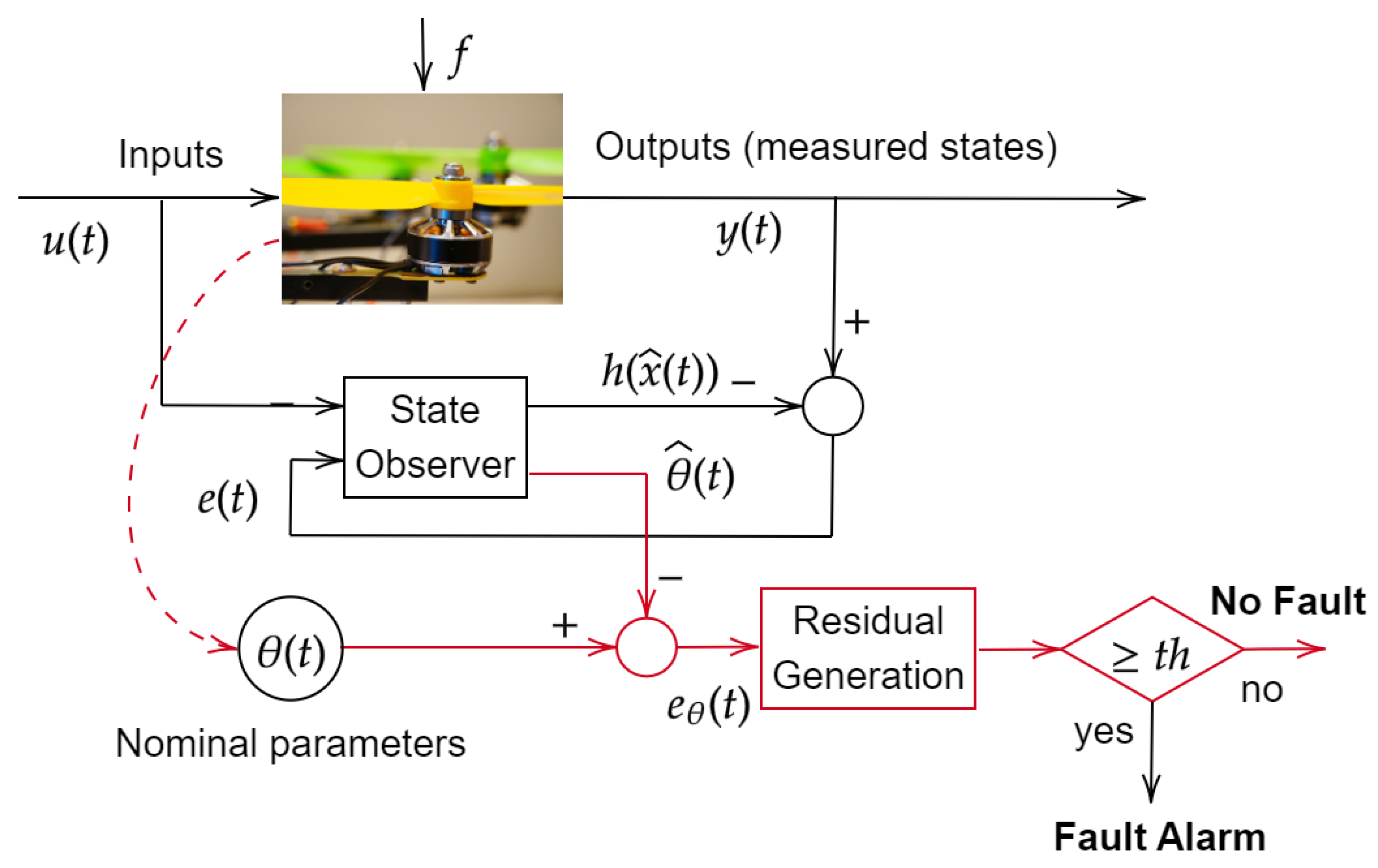
3.2. Model-Based Methods
3.3. Data-Based Methods
3.4. Summary
4. Conclusions
Author Contributions
Funding
Institutional Review Board Statement
Informed Consent Statement
Data Availability Statement
Conflicts of Interest
Abbreviations
| AE | Autoencoder |
| ANN | Artificial Neural Network |
| ARMA | Autoregressive–Moving-Average |
| CNN | Convolutional Neural Network |
| CWD | Choi–Williams Distribution |
| DC | Direct Current |
| DTCRV | Drive-Tolerant Current Residual Variance |
| DWT | Discrete Wavelet Transform |
| EBI | Energy-Based Index |
| ECC | Electrical Equivalent Circuit |
| EEMD | Ensemble Empirical Mode Decomposition |
| EMD | Empirical Mode Decomposition |
| EMF | Electromotive Force |
| FEA | Finite Element Analysis |
| FEM | Finite Element Method |
| FEMM | Finite Element Method Magnetic |
| FEI | Fasor Espacial Instantaneo |
| FFT | Fast Fourier Transform |
| FOC | Field-Oriented Control |
| GA | Genetic Algorithm |
| HA | Harmonic Analysis |
| ICA | Independent Component Analysis |
| IWFT | Improved Winding Function Theory |
| KF | Kalman Filter |
| KPCA | Kernel Principal Component Analysis |
| LDA | Linear Discriminant Analysis |
| LS | Least Squares |
| LSTM | Long Short-Term Memory |
| MBI | Mean-Based Index |
| MDS | Multi-Dimensional Scaling |
| MEC | Magnetic Equivalent Circuit |
| MCSA | Motor Current Signature Analysis |
| MPCC | Model Predictive Current Control |
| NCS | Neighborhood Component Analysis |
| NN | Neural Network |
| PWT | Packet Wavelet Transform |
| PSD | Power Spectral Density |
| PCA | Principal Component Analysis |
| PSO | Particle Swarm Optimization |
| RMS | Root Mean Square |
| RNN | Recurrent Neural Network |
| RUL | Remaining Useful Life |
| STFT | Short-Time Fourier Transform |
| SVD | Singular Value Decomposition |
| SVM | Support Vector Machine |
| SMO | Sliding Mode Observer |
| SSAE | Stacked Sparse Autoencoders |
| TDF | Time–Frecuency Distribution |
| VBI | Variance-Based Index |
| WFT | Winding Function Theory |
| WVD | Wigner–Ville Distribution |
References
- Moosavi, S.S.; Djerdir, A.; Amirat, Y.A.; Khaburi, D.A. Demagnetization fault diagnosis in permanent magnet synchronous motors: A review of the state-of-the-art. J. Magn. Magn. Mater. 2015, 391, 203–212. [Google Scholar] [CrossRef]
- Mohanraj, D.; Aruldavid, R.; Verma, R.; Sathyasekar, K.; Barnawi, A.; Chokkalingam, B.; Mihet-Popa, L. A Review of BLDC Motor: State of Art, Advanced Control Techniques, and Applications. IEEE Access 2022, 10, 54833–54869. [Google Scholar] [CrossRef]
- Chau, K.T. Stator-Permanent Magnet Motor Drives. In Electric Vehicle Machines and Drives: Design, Analysis and Application; Wiley-IEEE Press: Hoboken, NJ, USA, 2015; pp. 147–194. [Google Scholar] [CrossRef]
- Da, Y.; Shi, X.; Krishnamurthy, M. Health monitoring, fault diagnosis and failure prognosis techniques for Brushless Permanent Magnet Machines. In Proceedings of the 2011 IEEE Vehicle Power and Propulsion Conference, Chicago, IL, USA, 6–9 September 2011; pp. 1–7. [Google Scholar]
- Shifat, T.A.; Hur, J.W. An effective stator fault diagnosis framework of BLDC motor based on vibration and current signals. IEEE Access 2020, 8, 106968–106981. [Google Scholar] [CrossRef]
- Usman, A.; Doiphode, N.T.; Rajpurohit, B.S. Stator Winding Faults investigation in Permanent Magnet Synchronous Motor using Motor Signatures: Part I. In Proceedings of the 2019 International Conference on Electrical Drives & Power Electronics (EDPE), The High Tatras, Slovakia, 24–26 September 2019; pp. 160–168. [Google Scholar]
- Chen, Y.; Liang, S.; Li, W.; Liang, H.; Wang, C. Faults and diagnosis methods of permanent magnet synchronous motors: A review. Appl. Sci. 2019, 9, 2116. [Google Scholar] [CrossRef] [Green Version]
- Kim, K.T.; Park, J.K.; Hur, J.; Kim, B.W. Comparison of the fault characteristics of IPM-type and SPM-type BLDC motors under inter-turn fault conditions using winding function theory. IEEE Trans. Ind. Appl. 2013, 50, 986–994. [Google Scholar] [CrossRef]
- Vanchinathan, K.; Valluvan, K.R.; Gnanavel, C.; Gokul, C.; Albert, J.R. An improved incipient whale optimization algorithm based robust fault detection and diagnosis for sensorless brushless DC motor drive under external disturbances. Int. Trans. Electr. Energy Syst. 2021, 31, e13251. [Google Scholar] [CrossRef]
- Pietrzak, P.; Wolkiewicz, M. Stator Winding Fault Detection of Permanent Magnet Synchronous Motors Based on the Short-Time Fourier Transform. Power Electron. Drives 2022, 7, 112–133. [Google Scholar] [CrossRef]
- Hosseini, F.; Abedi, M.; Mohammad Hosseini, S. Classification of Multiple Electromechanical Faults in BLDC Motors Using Neural Networks and Optimization Algorithms. Res. Technol. Electr. Ind. 2022, 1, 114–124. [Google Scholar]
- Lee, S.T.; Hur, J. Detection technique for stator inter-turn faults in BLDC motors based on third-harmonic components of line currents. IEEE Trans. Ind. Appl. 2016, 53, 143–150. [Google Scholar] [CrossRef]
- Lee, S.T.; Kim, K.T.; Hur, J. Diagnosis technique for stator winding inter-turn fault in BLDC motor using detection coil. In Proceedings of the 2015 9th International Conference on Power Electronics and ECCE Asia (ICPE-ECCE Asia), Seoul, Republic of Korea, 1–5 June 2015; pp. 2925–2931. [Google Scholar]
- Antunes, H.; Fonseca, D.; Cardoso, A. Symmetrical Six-Phase Induction Motor Stator Faults Diagnostics Approach, Immune to Unbalanced Supply Voltage, Based on the Analysis of the Midpoint Electrical Potential of the Stator Star. Eng. Proc. 2022, 24, 22. [Google Scholar]
- Usman, A.; Doiphode, N.T.; Rajpurohit, B.S. Finite Element Modeling of Stator Winding Faults in Permanent Magnet Synchronous Motor: Part II. In Proceedings of the 2019 International Conference on Electrical Drives & Power Electronics (EDPE), The High Tatras, Slovakia, 24–26 September 2019; pp. 169–176. [Google Scholar]
- Wang, H.; Qian, G.; Cao, W.; Lu, S. A Two-Step Online Fault Detection Method for High-Resistance Connection Faults in a Vehicular BLDC Motor. In Advanced Sensors and Sensing Technologies for Electric Vehicles; AIP Publishing LLC Melville: New York, NY, USA, 2022; p. 1. [Google Scholar]
- Gupta, A.; Jayaraman, K.; Reddy, R. Performance Analysis and Fault Modelling of High Resistance Contact in Brushless DC Motor Drive. In Proceedings of the IECON 2021—47th Annual Conference Of The IEEE Industrial Electronics Society, Toronto, ON, Canada, 13–16 October 2021; pp. 1–6. [Google Scholar]
- Isermann, R. Fault-Diagnosis Applications: Model-Based Condition Monitoring: Actuators, Drives, Machinery, Plants, Sensors, and Fault-Tolerant Systems; Springer Science & Business Media: Berlin/Heidelberg, Germany, 2011. [Google Scholar]
- Suawa, P.; Meisel, T.; Jongmanns, M.; Huebner, M.; Reichenbach, M. Modeling and Fault Detection of Brushless Direct Current Motor by Deep Learning Sensor Data Fusion. Sensors 2022, 22, 3516. [Google Scholar] [CrossRef]
- Ding, S.X. Data-Driven Design of Fault Diagnosis and Fault-Tolerant Control Systems; Springer: Berlin/Heidelberg, Germany, 2014. [Google Scholar]
- Jafari, A.; Faiz, J.; Jarrahi, M.A. A simple and efficient current-based method for interturn fault detection in BLDC motors. IEEE Trans. Ind. Inform. 2020, 17, 2707–2715. [Google Scholar] [CrossRef]
- Park, J.K.; Seo, I.M.; Hur, J. Fault type detection using frequency pattern of stator current in IPM-type BLDC motor under stator inter-turn, dynamic eccentricity, and coupled faults. In Proceedings of the 2013 IEEE Energy Conversion Congress and Exposition, Denver, CO, USA, 15–19 September 2013; pp. 2516–2521. [Google Scholar]
- Usman, A.; Rajpurohit, B.S. Detection and Identification of Stator Inter-turn Faults and Demagnetization effects in Hybrid Analytical-Numerical model of a BLDC Motor using Electromagnetic Signatures. In Proceedings of the 2020 IEEE Texas Power and Energy Conference (TPEC), College Station, TX, USA, 6–7 February 2020; pp. 1–7. [Google Scholar]
- Usman, A.; Rajpurohit, B.S. Numerical Analysis of Stator Inter-turn Fault and Demagnetization effect on a BLDC Motor using Electromagnetic Signatures. In Proceedings of the 2020 IEEE International Conference on Power Electronics, Smart Grid and Renewable Energy (PESGRE2020), Cochin, India, 2–4 January 2020; pp. 1–6. [Google Scholar]
- Usman, A.; Rajpurohit, B.S. Modeling and Classification of Stator Inter-Turn Fault and Demagnetization Effects in BLDC Motor Using Rotor Back-EMF and Radial Magnetic Flux Analysis. IEEE Access 2020, 8, 118030–118049. [Google Scholar] [CrossRef]
- Acevedo, R.J.; Piña, F.J.V.; Salas, R.Á.; Zárate, C.H.S. Diagnóstico de falla eléctrica de estator en motores bldc de vehículo ligero en diferentes regímenes de velocidad mediante la transforma discreta de fourier (stator’s electric fault diagnosis in bldc motors of light vehicle in different velocity regimes by means of the discret fourier’s transform). Pist. Educ. 2020, 42, 337–347. [Google Scholar]
- Maldonado Ruelas, V.A.; Villalobos Piña, F.J.; Alvarez Salas, R.; Morones Alba, J.A.; Ortiz Medina, R.A. Detección de fallos multicriterio de un motor BLDC (Brushless Direct Current). DYNA-Ing. Ind. 2018, 93, 556–562. [Google Scholar]
- Wang, H.; Wang, J.; Wang, X.; Lu, S.; Hu, C.; Cao, W. Detection and Evaluation of the Inter-turn Short Circuit Fault in a BLDC-Based Hub Motor. IEEE Trans. Ind. Electron. 2022, 70, 3055–3068. [Google Scholar] [CrossRef]
- Frisk, E. Residual Generation for Fault Diagnosis. Ph.D. Thesis, Linköpings Universitet, Linköping, Sweden, 2001. [Google Scholar]
- El Mekki, A.; Saad, K.B. A BLDC fault diagnosis approach based on a super-twisting sliding mode observer. In Proceedings of the 2016 4th International Conference on Control Engineering & Information Technology (CEIT), Hammamet, Tunisia, 16–18 December 2016; pp. 1–5. [Google Scholar]
- El Mekki, A.; SAAD, K.B. Diagnosis based on a sliding mode observer for an inter-turn short circuit fault in brushless dc motors. Rev. Roum. Sci. Tech. Electrotech. Energétique 2018, 63, 391–396. [Google Scholar]
- Moseler, O.; Isermann, R. Model-based fault detection for a brushless DC motor using parameter estimation. In Proceedings of the IECON’98. Proceedings of the 24th Annual Conference of the IEEE Industrial Electronics Society (Cat. No. 98CH36200), Aachen, Germany, 31 August–4 September 1998; Volume 4, pp. 1956–1960. [Google Scholar]
- Moseler, O.; Isermann, R. Application of model-based fault detection to a brushless DC motor. IEEE Trans. Ind. Electron. 2000, 47, 1015–1020. [Google Scholar] [CrossRef]
- Taqvi, S.A.A.; Zabiri, H.; Tufa, L.D.; Uddin, F.; Fatima, S.A.; Maulud, A.S. A review on data-driven learning approaches for fault detection and diagnosis in chemical processes. ChemBioEng Rev. 2021, 8, 239–259. [Google Scholar] [CrossRef]
- Park, J.K.; Jeong, C.L.; Lee, S.T.; Hur, J. Early detection technique for stator winding inter-turn fault in BLDC motor using input impedance. IEEE Trans. Ind. Appl. 2014, 51, 240–247. [Google Scholar] [CrossRef]
- Borja, C.A.; Tisado, K.J.; Ostia, C. Fault Diagnosis of a Brushless DC Motor Using K-Nearest Neighbor Classification Technique with Discrete Wavelet Transform Feature Extraction. In Proceedings of the 2022 IEEE 14th International Conference on Computer and Automation Engineering (ICCAE), Brisbane, Australia, 25–27 March 2022; pp. 122–126. [Google Scholar]
- Kim, T.; Lee, H.W.; Kwak, S. The internal fault analysis of brushless DC motors based on the winding function theory. IEEE Trans. Magn. 2009, 45, 2090–2096. [Google Scholar]
- Da, Y.; Shi, X.; Krishnamurthy, M. A new approach to fault diagnostics for permanent magnet synchronous machines using electromagnetic signature analysis. IEEE Trans. Power Electron. 2012, 28, 4104–4112. [Google Scholar] [CrossRef]
- Shifat, T.A.; Jang-Wook, H. Remaining Useful Life Estimation of BLDC Motor Considering Voltage Degradation and Attention-Based Neural Network. IEEE Access 2020, 8, 168414–168428. [Google Scholar] [CrossRef]
- Hadef, M.; Mekideche, M.R.; Djerdir, A.; N’diaye, A.O. Turn-to-Turn Short Circuit Faults between Two Phases in Permanent Magnet Synchronous Motor Drives. Jordan J. Electr. Eng. 2017, 3, 208–222. [Google Scholar]
- Qi, J.; Wan, H. A Detection Method of Phase Failure of PMSM Based on Deep Learning. In Proceedings of the 2020 IEEE Chinese Automation Congress (CAC), Shanghai, China, 6–8 November 2020; pp. 5591–5595. [Google Scholar]
- Bao, L.; Yao, G.; Chen, S.; Wang, Z.; Hu, X.; Huang, Y. An On-line Detection Method for Single-Phase Inter-Turn Fault Occurring in High-Speed PMSM. In Proceedings of the 2020 IEEE 23rd International Conference on Electrical Machines and Systems (ICEMS), Hamamatsu, Japan, 24–27 November 2020; pp. 1095–1100. [Google Scholar]
- Ullah, Z.; Hur, J. Analysis of Inter-Turn-Short Fault in an FSCW IPM Type Brushless Motor Considering Effect of Control Drive. IEEE Trans. Ind. Appl. 2020, 56, 1356–1367. [Google Scholar] [CrossRef]
- Pietrzak, P.; Wolkiewicz, M. Application of Support Vector Machine to stator winding fault detection and classification of permanent magnet synchronous motor. In Proceedings of the 2021 IEEE 19th International Power Electronics and Motion Control Conference (PEMC), Gliwice, Poland, 25–29 April 2021; pp. 880–887. [Google Scholar]
- Zhao, J.; Guan, X.; Li, C.; Mou, Q.; Chen, Z. Comprehensive Evaluation of Inter-Turn Short Circuit Faults in PMSM Used for Electric Vehicles. IEEE Trans. Intell. Transp. Syst. 2021, 22, 611–621. [Google Scholar] [CrossRef]
- Maraaba, L.S.; Milhem, A.S.; Nemer, I.A.; Al-Duwaish, H.; Abido, M.A. Convolutional neural network-based inter-turn fault diagnosis in LSPMSMs. IEEE Access 2020, 8, 81960–81970. [Google Scholar] [CrossRef]
- Palavicino, P.C.; Lee, W.; Sarlioglu, B. Detection and Compensation of Inter-turn Short Circuit in Interior Permanent Magnet Synchronous Machines with 2-level Voltage Source Inverter. In Proceedings of the 2020 IEEE Energy Conversion Congress and Exposition (ECCE), Detroit, MI, USA, 11–15 October 2020; pp. 4460–4465. [Google Scholar]
- Vasilios, I.C. Detection of PMSM Inter-Turn Short-Circuit Based on a Fault-Related Disturbance Observer. Int. J. Simul. Syst. Sci. Technol. 2020, 21. [Google Scholar] [CrossRef]
- Zhang, J.; Wang, Y.; Zhu, K.; Zhang, Y.; Li, Y. Diagnosis of Interturn Short-Circuit Faults in Permanent Magnet Synchronous Motors Based on Few-Shot Learning Under a Federated Learning Framework. IEEE Trans. Ind. Inform. 2021, 17, 8495–8504. [Google Scholar] [CrossRef]
- Park, C.H.; Lee, J.; Kim, H.; Suh, C.; Youn, M.; Shin, Y.; Ahn, S.H.; Youn, B.D. Drive-Tolerant Current Residual Variance (DTCRV) for Fault Detection of a Permanent Magnet Synchronous Motor Under Operational Speed and Load Torque Conditions. IEEE Access 2021, 9, 49055–49068. [Google Scholar] [CrossRef]
- Liang, H.; Chen, Y.; Liang, S.; Wang, C. Fault detection of stator inter-turn short-circuit in PMSM on stator current and vibration signal. Appl. Sci. 2018, 8, 1677. [Google Scholar] [CrossRef] [Green Version]
- Attestog, S.; Van Khang, H.; Robbersmyr, K.G. Improved Quadratic Time-frequency Distributions for Detecting Inter-turn Short Circuits of PMSMs in Transient States. In Proceedings of the 2020 IEEE International Conference on Electrical Machines (ICEM), Gothenburg, Sweden, 23–26 August 2020; Volume 1, pp. 1461–1467. [Google Scholar]
- Otava, L.; Buchta, L. Integrated diagnostic system for winding fault detection of the three-phase PMSM. In Proceedings of the 2020 IEEE 12th International Congress on Ultra Modern Telecommunications and Control Systems and Workshops (ICUMT), Brno, Czech Republic, 5–7 October 2020; pp. 33–40. [Google Scholar]
- Gao, F.; Zhang, G.; Li, M.; Gao, Y.; Zhuang, S. Inter-turn fault identification of surface-mounted permanent magnet synchronous motor based on inverter harmonics. Energies 2020, 13, 899. [Google Scholar] [CrossRef] [Green Version]
- Mansouri, B.; Idrissi, H.J.; Venon, A. Inter-Turn Short-Circuit Failure of PMSM Indicator based on Kalman Filtering in Operational Behavior. Annual Conference of the PHM Society. 2019, Volume 11. Available online: https://pdfs.semanticscholar.org/bdb7/5c0d0e604ebc7353d71078c6bf51b7f78c0b.pdf (accessed on 1 December 2022).
- Zerdani, S.; El Hafyani, M.L.; Zouggar, S. Inter-Turn Stator Winding fault Diagnosis for Permanent Magnet Synchronous Motor based Power Spectral Density Estimators. In Proceedings of the 2020 IEEE International Conference on Smart Grid and Clean Energy Technologies (ICSGCE), Kuching, Malaysia, 4–7 October 2020; pp. 137–142. [Google Scholar]
- Yassa, N.; Rachek, M. Modeling and detecting the stator winding inter turn fault of permanent magnet synchronous motors using stator current signature analysis. Math. Comput. Simul. 2020, 167, 325–339. [Google Scholar] [CrossRef]
- Cui, R.; Fan, Y.; Li, C. On-line inter-turn short-circuit fault diagnosis and torque ripple minimization control strategy based on OW five-phase BFTHE-IPM. IEEE Trans. Energy Convers. 2018, 33, 2200–2209. [Google Scholar] [CrossRef]
- Yang, Y.; Chen, Y.; Hao, W. Online detection of inter-turn short-circuit fault in dual-redundancy permanent magnet synchronous motor. IET Electr. Power Appl. 2021, 15, 104–113. [Google Scholar] [CrossRef]
- Gao, C.; Lv, K.; Si, J.; Feng, H.; Hu, Y. Research on Inter-turn Short Circuit Fault Indicators for Direct-drive Permanent Magnet Synchronous Motor. IEEE J. Emerg. Sel. Top. Power Electron. 2021, 10, 1902–1914. [Google Scholar] [CrossRef]
- Rosero, J.; Romeral, L.; Ortega, J.; Rosero, E. Short-circuit detection by means of empirical mode decomposition and Wigner–Ville distribution for PMSM running under dynamic condition. IEEE Trans. Ind. Electron. 2009, 56, 4534–4547. [Google Scholar] [CrossRef]
- Barendse, P.; Pillay, P. A new algorithm for the detection of faults in permanent magnet machines. In Proceedings of the IECON 2006-32nd Annual Conference on IEEE Industrial Electronics, Paris, France, 6–10 November 2006; pp. 823–828. [Google Scholar]
- Urresty, J.; Riba, J.; Romeral, L.; Saavedra, H. Analysis of demagnetization faults in surface-mounted permanent magnet synchronous with inter-turns and phase-to-ground short-circuits. In Proceedings of the 2012 IEEE XXth International Conference on Electrical Machines, Marseille, France, 2–5 September 2012; pp. 2384–2389. [Google Scholar]
- Xiangli, K.; Ma, R.; Zhang, Q.; Wang, W. Modeling and Simulation of Short Circuit Faults in Stator Coils of Brushless DC Motor. In Mechatronics and Automatic Control Systems; Springer: Berlin/Heidelberg, Germany, 2014; pp. 35–45. [Google Scholar]
- Wang, Z.; Yang, J.; Cao, C.; Gu, Z. Phase-phase short fault analysis of permanent magnet synchronous motor in electric vehicles. Energy Procedia 2016, 88, 915–920. [Google Scholar] [CrossRef] [Green Version]
- Shao, M.; Yang, G.; Sun, G.; Su, J. A method of open circuit fault diagnosis for five-phase permanent magnet synchronous motor based on wavelet analysis. In Proceedings of the 2019 IEEE 22nd International Conference on Electrical Machines and Systems (ICEMS), Harbin, China, 11–14 August 2019; pp. 1–6. [Google Scholar]
- Kontarček, A.; Bajec, P.; Nemec, M.; Ambrožič, V.; Nedeljković, D. Cost-effective three-phase PMSM drive tolerant to open-phase fault. IEEE Trans. Ind. Electron. 2015, 62, 6708–6718. [Google Scholar] [CrossRef]
- Huang, W.; Du, J.; Hua, W.; Lu, W.; Bi, K.; Zhu, Y.; Fan, Q. Current-based open-circuit fault diagnosis for PMSM drives with model predictive control. IEEE Trans. Power Electron. 2021, 36, 10695–10704. [Google Scholar] [CrossRef]
- Slimen, S.B.; Bourogaoui, M.; Sethom, H.B.A. Easy and effective multiple faults detection and localization method for PMSM drives. In Proceedings of the 2019 IEEE International Conference on Advanced Systems and Emergent Technologies (IC_ASET), Hammamet, Tunisia, 19–22 March 2019; pp. 311–316. [Google Scholar]
- Abed, W.; Sharma, S.; Sutton, R. Fault diagnosis of brushless DC motor for an aircraft actuator using a neural wavelet network. In Proceedings of the IET Conference on Control and Automation 2013: Uniting Problems and Solutions, Birmingham, UK, 4–5 June 2013. [Google Scholar]
- Neethu, S.; Sreelekha, V. Hysteresis controller based open phase fault tolerant control of BLDC motor drives. In Proceedings of the 2014 IEEE International Conference on Power Signals Control and Computations (EPSCICON), Thrissur, India, 6–11 January 2014; pp. 1–6. [Google Scholar]
- Fu, Z.; Liu, X.; Liu, J. Research on the fault diagnosis of dual-redundancy BLDC motor. In Proceedings of the ICPE 2020—The International Conference on Power Engineering, Guangzhou, China, 4–6 December 2020; pp. 17–22. [Google Scholar]


| Periodic Signals | Stochastic Signals | Non-Stationary Signals | |
|---|---|---|---|
| Methods | Bandpass Filtering, Fourier Analysis, Parametric Spectral Estimation, Correlation Analysis | Correlation Analysis, CUSUM, Kalman Filter, ARMA | ARMA, STFT, Wavelet Analysis, Detrend Fluctuation Analysis |
| Reference | Main Methods | Measured Variables | S or E |
|---|---|---|---|
| [22] | PSD | Phase currents | S and E |
| [12] | HA | Line currents | S and E |
| [23,24,25] | HA, FEM | Phase currents, Back-EMF, electromagnetic torque, velocity | S |
| [26] | FFT | Phase currents | E |
| [27] | FFT, DWT | Phase currents | E |
| [21] | MBI, VBI, EBI | Phase currents | S and E |
| [10] | Bispectrum analysis | Phase currents | E |
| [28] | FFT | Phase currents | S and E |
| Reference | Main Methods | Measured Variables | S or E |
|---|---|---|---|
| [11] | Wavelets, ANN, PSO, Gf | Motor torque, motor speed | S |
| [13] | Logic comparison, FEM | Back-EMF | S and E |
| [35] | WFT, FEA | Phase currents and voltages | S and E |
| Supervised Learning | Unsupervised Learning | |
|---|---|---|
| Methods | Bayesian Network, Random Forest, Decision Tree, k-Nearest Neighbors, Fisher’s Discriminant Analysis, Artificial Neural Networks, Support Vector Machine | Principal Component Analysis, Partial Least Square, Independent Component Analysis, Autoencoders |
| Features | (1) Require both input and output system data. (2) Require labeled data. (3) Predict the output. (4) Requiere supervision for training. | (1) Require only input system data. (2) Employ unlabeled data. (3) Find hidden patterns in data. (4) Do not requiere supervision for training. |
| Computational Complexity | (1) Very complex. (2) Require feedback to improve the accuracy of the prediction. | (1) Less complex. (2) No feedback is needed. |
| Learning | Offline learning (usually) | Online learning |
| End Goal | Predict an output. Develop a model to (1) predict new values or (2) understand existing relationship between input and output data. | Gain insight from data. Develop a model to (1) place observations from a dataset into a specific cluster or (2) create rules to identify associations between variables. |
| Subtypes | (1) Regression and (2) classification. | (1) Clstering and (2) association. |
| Performance | More accurate | Less accurate |
| Fault Classes | Known in advance | Not known in advance |
| Method | Advantages | Disadvantages |
|---|---|---|
| Model-based | (1) Can be naturally integrated into a fault-tolerant control scheme. (2) Can be highly accurate. (3) Requires less data than data-based methods. (4) All phases of diagnosis (detection, isolation and identification) can be conceived using the same model. (5) Few hard sensors are required with respect to the other methods. | (1) They requiere well-calibrated models. (2) Real-life system physics is often too stochastic and complex to model. (3) Sample time (or sample frequency) is important. |
| Data-based | (1) Do not require some model based on the physics of the BLDC motor. (2) Therefore, they are suitable for applications where a model is not available. (3) Suitable for processes with many sensed variables (i.e., when a large quantity of data is available). (4) Sample time (or sample frequency) is not important. | (1) Diagnosis accuracy relies on data quantity and quality. (2) Historical data on the behavior of the BLDC throughout its active life is required. (3) A sizable quantity of sensors is required. |
| Signal-based | (1) Do not require some model based on the physics of the BLDC motor. (2) Historical information about the BLDC motor is not required. | (1) Risk of false alarms due to disturbances and changes in the BLDC operating conditions. (2) High-speed computing power for transforming signals in real time. (3) The accuracy of the diagnosis depends on the quality of the sensors that provide the signals. (4) Sample time (or sample frequency) is important. |
| Type of Fault | Method | Physical Variables | Implementation | Comp. Burden |
|---|---|---|---|---|
| Inter-Turn | FEM, KF, HA [12] | Current | S, E, ON-L | High |
| Spectral methods, SVM methods [4] | Current | S, OFF-L | Medium | |
| WFT, FEM [8] | Inductance, torque, voltage | S, E, OFF-L | Medium | |
| WFT, FEM, [37] | Back-EMF, current | S, E, OFF-L | Medium | |
| WFT, FFT [35] | Impedance, current, voltage, coil resistance | S, E, OFF-L | Low | |
| Search coils, FEA [38] | Magnetic flux, voltage | S, E, OFF-L | High | |
| Hybrid analytical-numerical approach, ECC, FEMM [23] | Current | Co-S, OFF-L | High | |
| FFT, Park’s phasor analysis [26] | Current | S, OFF-L | Medium | |
| ECC, MEC, numerical methods, hybrid models, IWFT [25] | Current | S, Co-S, E, OFF-L | High, medium (depending on the method) | |
| RUL, RNN, LSTM [39] | Voltage, torque, temperature, velocity, current | S, E, OFF-L | High | |
| Technique based on undulations in velocity [40] | Velocity | E, OFF-L | Low | |
| Self-encoding convolutional network model [41] | Phase currents | S, OFF-L (applicable online) | High | |
| LS, AE [42] | Resistivity, inductance, voltage | S, OFF-L (applicable online) | High | |
| Co-simulation multidomain technique, FEM [43] | Flux density, current, torque vibrations | Co-S, E, OFF-L | Medium | |
| SVW, FFT [44] | Currents | S, E, OFF-L | Medium | |
| FEI, FFT, WDT [27] | Current | S, E, OFF-L | High | |
| FEM [45] | Current, voltage, electromagnetic torque, temperature | S, E, OFF-L | Medium | |
| CNN [46] | Current | S, E, OFF-L | High | |
| Current observer [47] | Voltage, current, position, velocity | S, E, OFF-L | Low | |
| Sliding mode observer (SMO) [48] | Current, voltage | S, ON-L | Low | |
| SSAE, Siamese neural networks [49] | Current, impedance, torque | S, E, ON-L | High | |
| DTCRV [50] | Current | S, E, OFF-L | Low | |
| Wave packet transform [51] | Current, vibration signal of the stator | E, OFF-L | High | |
| TDF, WVD, CWD [52] | Current | S, E, OFFL | Medium | |
| KF [53] | Current, BEMF | S, E, OFF-L | Medium | |
| FFT [54] | Phase voltages | S, OFF-L | Medium | |
| KF [55] | Voltage (voltage residuals) | S, ON-L | High | |
| Spectral density estimator (PSD), Welch and Burg method [56] | Current | S, OFF-L | High | |
| PSD, MCSA [57] | Current | S, OFF-L | Medium | |
| Maxwel II. 2D, numerical methods, FEM [24] | eletromagnetic magnitude, phase currents, BFEM, Electromagnetic torque, velocity, magnetic flux density, flux linkage | Co-S, OFF-L | High | |
| Math models [58] | Current, torque | S, ON-L | Medium | |
| Arithmetic mean [59] | Current, position | S, OFF-L | Low | |
| FEM [60] | Electromagnetic torque | S, E, OFF-L | High | |
| KF [9] | Phase currents | S, ON-L | Low High | |
| FEM, EMD, WVD [61] | Current | S, OFF-L | High | |
| Coil-to-coil | Fast Kurtogram autogram, MCSA [5] | Vibration, current | E, OFF-L | High |
| MCSA [62] | Current | S, E, OFF-L | Medium | |
| Phase-to-phase | FEM numerical methods [15] | BFEM, magnetic flux density, phase current | S, OFF-L | High |
| FEM [63] | None | S, OFF-L | High | |
| Math model [64] | Self-inductions, mutual inductance, current | S, OFF-L | Medium | |
| DWT, ANN [65] | Voltage, current, sequence current negative | S, OFF-L | High | |
| Open circuit | Wavelet transform, SVM, DWT, NCA [66] | Current | S, OFF-L | High |
| FOC, current comparison method (voltage error) [67] | Current | S, E, OFF-L | Medium | |
| MPCC [68] | Current | S, E, OFF-L | Medium | |
| RMS [69] | Normalized current | S, OFF-L | Low | |
| DWT, NN [70] | Current, velocity | S, OFF-L | High | |
| Current residual [71] | Current, torque, voltage | S, ON-L | Low | |
| FFT [16] | Impedances | S, E, OFF-L | Low | |
| FEM and function wavelets [72] | Current | S, OFF-L | High |
Disclaimer/Publisher’s Note: The statements, opinions and data contained in all publications are solely those of the individual author(s) and contributor(s) and not of MDPI and/or the editor(s). MDPI and/or the editor(s) disclaim responsibility for any injury to people or property resulting from any ideas, methods, instructions or products referred to in the content. |
© 2022 by the authors. Licensee MDPI, Basel, Switzerland. This article is an open access article distributed under the terms and conditions of the Creative Commons Attribution (CC BY) license (https://creativecommons.org/licenses/by/4.0/).
Share and Cite
Solís, R.; Torres, L.; Pérez, P. Review of Methods for Diagnosing Faults in the Stators of BLDC Motors. Processes 2023, 11, 82. https://doi.org/10.3390/pr11010082
Solís R, Torres L, Pérez P. Review of Methods for Diagnosing Faults in the Stators of BLDC Motors. Processes. 2023; 11(1):82. https://doi.org/10.3390/pr11010082
Chicago/Turabian StyleSolís, Ricardo, Lizeth Torres, and Pablo Pérez. 2023. "Review of Methods for Diagnosing Faults in the Stators of BLDC Motors" Processes 11, no. 1: 82. https://doi.org/10.3390/pr11010082