
Evaluation of the Performance of a Heat Pipe for Pre-Frozen Soil around a Solar Support by a Numerical Method

Abstract
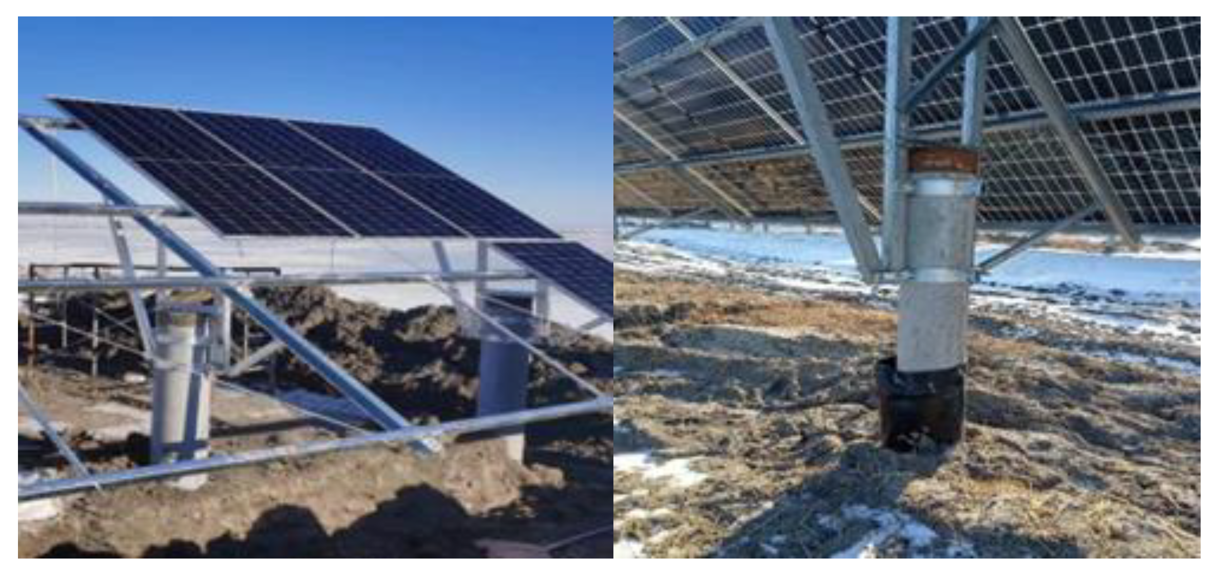
:1. Introduction
2. Method
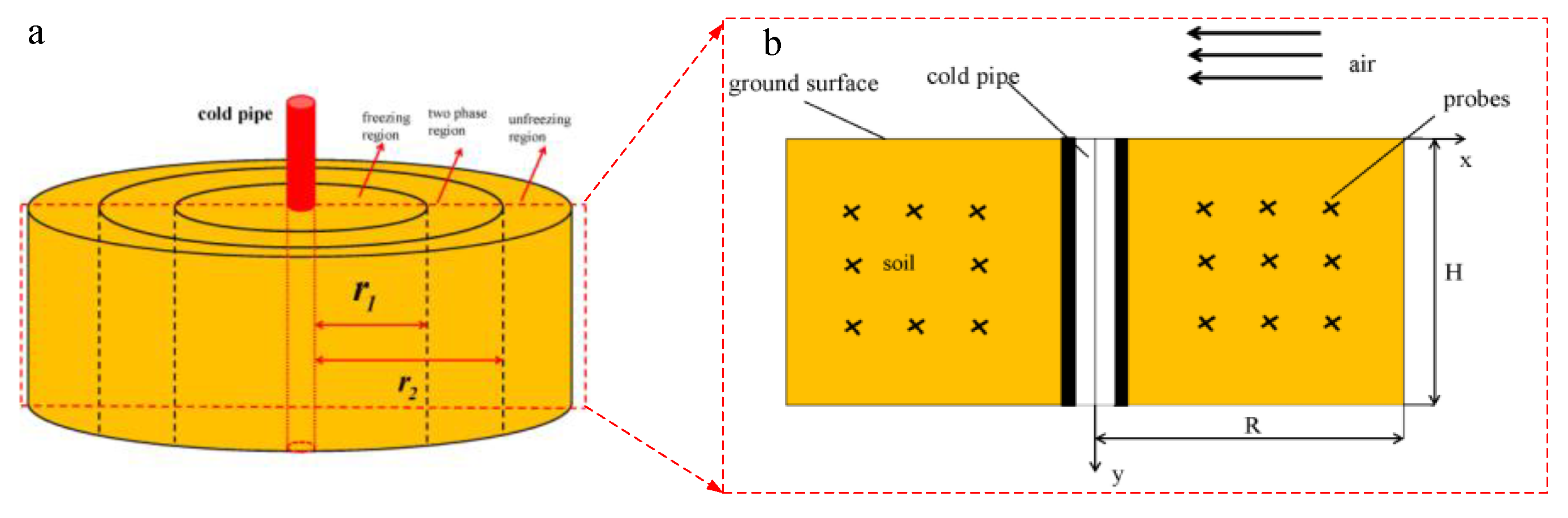
2.1. Mathematical Model
- The water in soil pores is an incompressible fluid, and convective heat transfer is ignored.
- The soil is considered an isotropic porous medium with pores filled with water, and the volume change of water during phase transition is ignored.
- The soil particles are rigid, and the thermophysical properties are independent of temperature.
- The temperature of the heat pipe is constant.
2.2. Governing Equations and Boundary Conditions
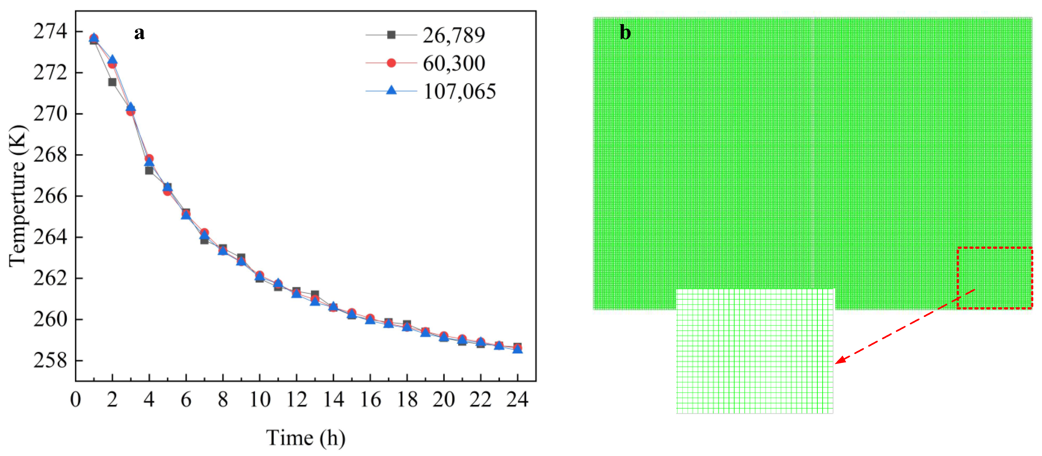
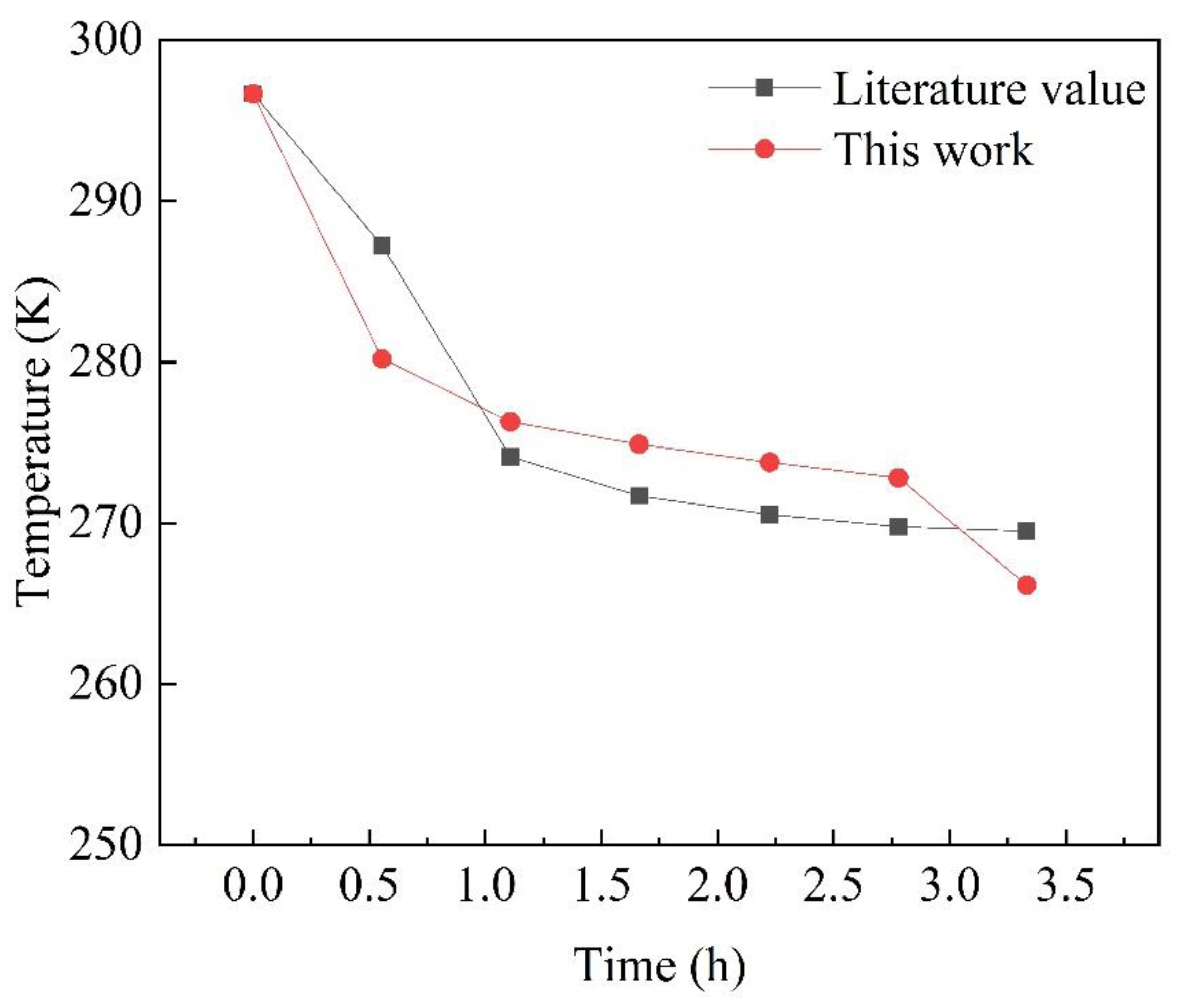
2.3. Solution and Validation of the Model
3. Results and Discussion
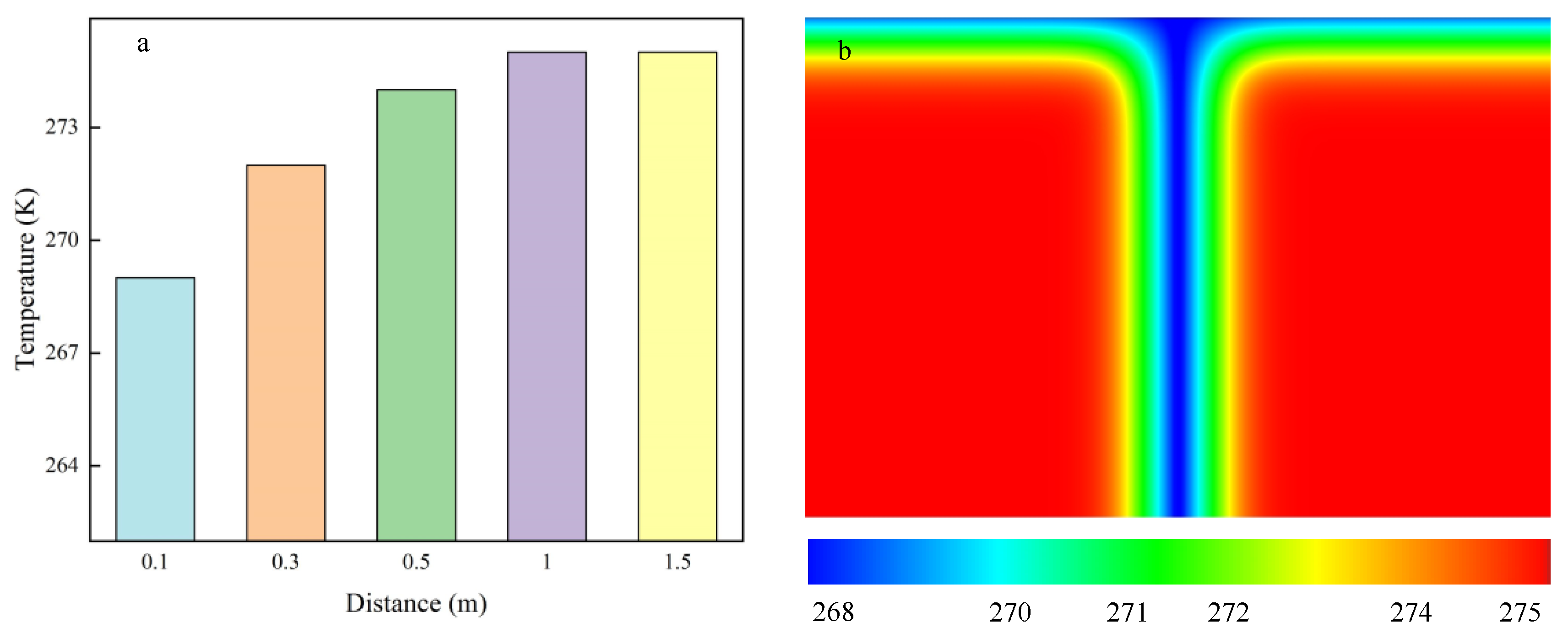
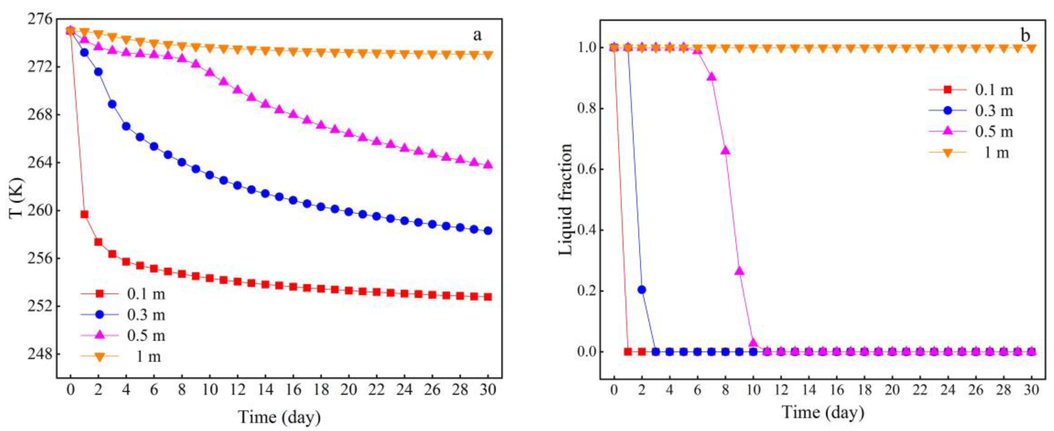
3.1. Spatiotemporal Characteristics of Soil Freezing
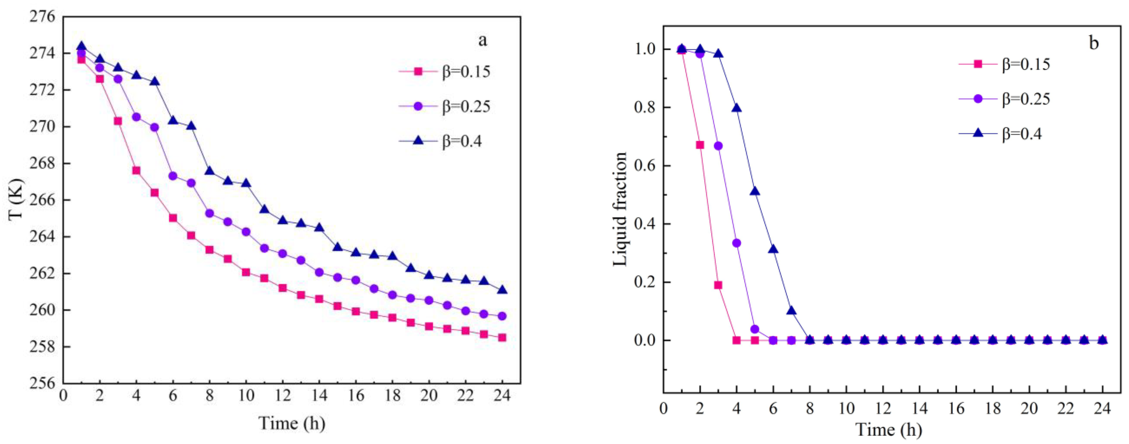
3.2. Effects of Soil Moisture Content on Freezing
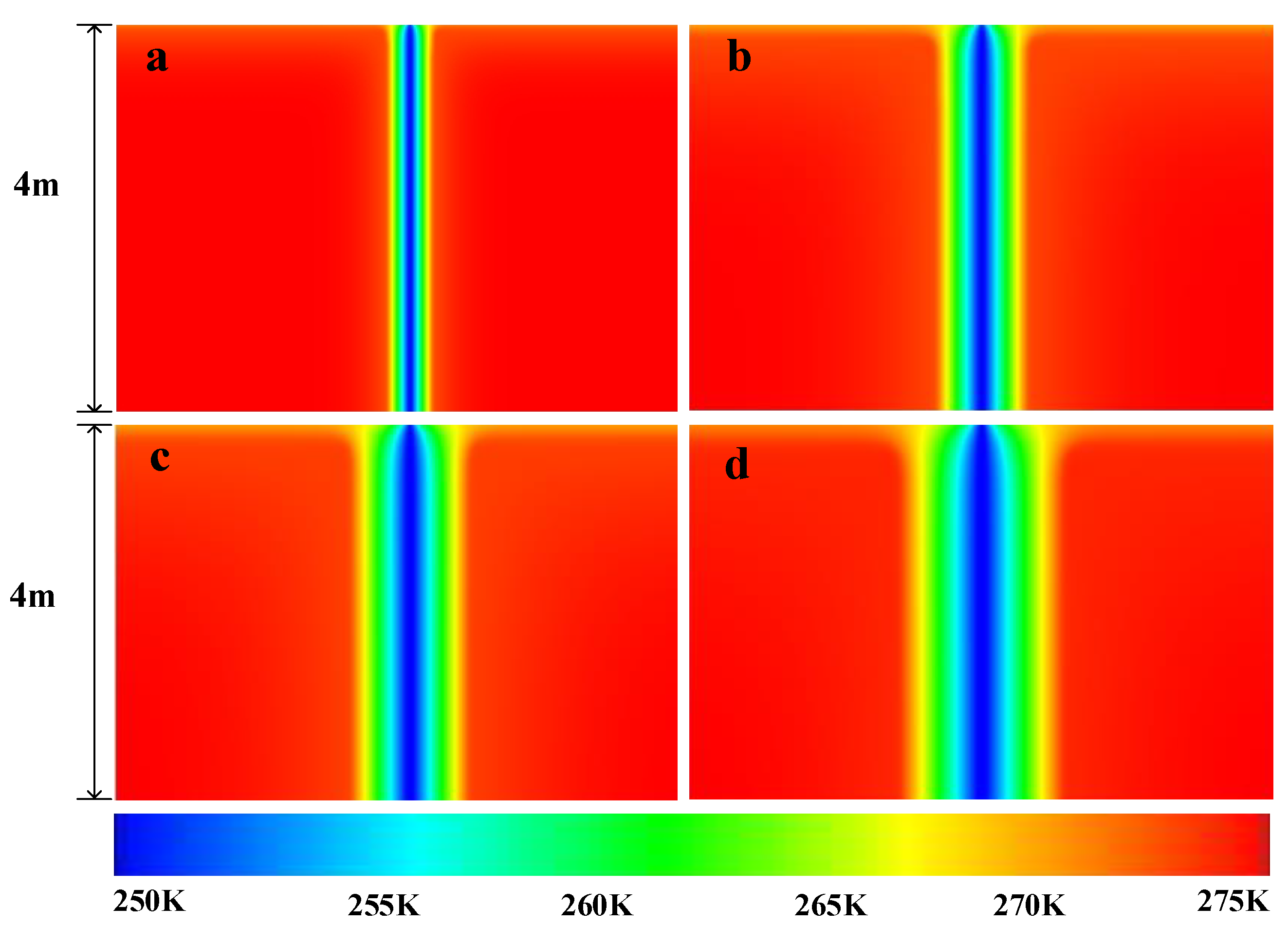
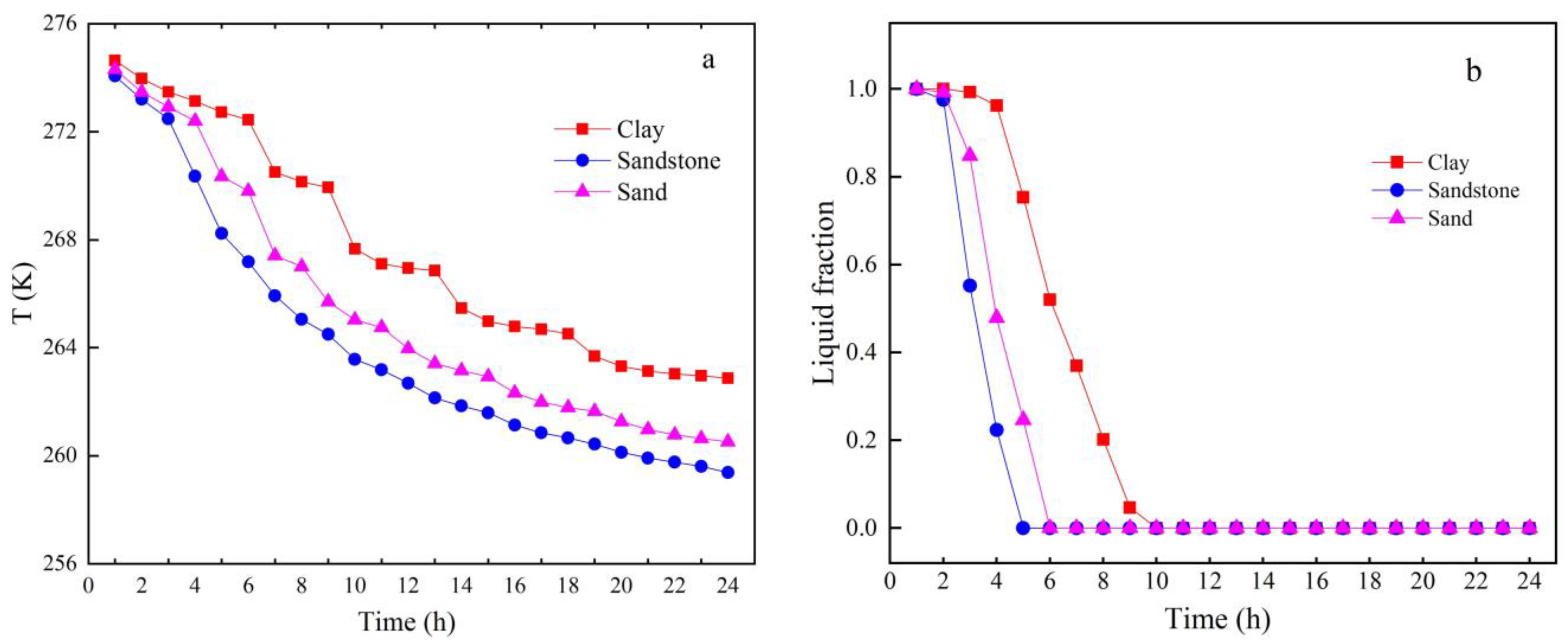
3.3. Effects of Soil Types on Freezing
4. Conclusions
Author Contributions
Funding
Institutional Review Board Statement
Informed Consent Statement
Data Availability Statement
Conflicts of Interest
References
- Guler, E.; Kandemir, S.Y.; Acikkalp, E.; Ahmadi, M.H. Evaluation of sustainable energy performance for OECD countries. Energy Sources Part B Econ. Plan. Policy 2021, 16, 491–514. [Google Scholar] [CrossRef]
- Açıkkalp, E.; Kandemir, S.Y. A method for determining optimum insulation thickness: Combined economic and environmental method. Therm. Sci. Eng. Prog. 2019, 11, 249–253. [Google Scholar] [CrossRef]
- Açıkkalp, E.; Kandemir, S.Y.; Ahmadi, M.H. Solar driven Stirling engine—Chemical heat pump—Absorption refrigerator hybrid system as environmental friendly energy system. J. Environ. Manag. 2019, 232, 455–461. [Google Scholar] [CrossRef] [PubMed]
- Hassan, A.A.; Elwardany, A.E.; Ookawara, S.; El-Sharkawy, I.I. Performance investigation of a solar-powered adsorption-based trigeneration system for cooling, electricity, and domestic hot water production. Appl. Therm. Eng. 2021, 199, 117553. [Google Scholar] [CrossRef]
- Jiang, B.; Lougou, B.G.; Zhang, H.; Wang, W.; Han, D.; Shuai, Y. Analysis of high-flux solar irradiation distribution characteristic for solar thermochemical energy storage application. Appl. Therm. Eng. 2020, 181, 115900. [Google Scholar] [CrossRef]
- Shan, W.; Zhang, C.; Guo, Y.; Qiu, L.; Xu, Z.; Wang, Y. Spatial Distribution and Variation Characteristics of Permafrost Temperature in Northeast China. Sustainability 2022, 14, 8178. [Google Scholar] [CrossRef]
- Ding, F.; Song, L.; Yue, F. Study on Mechanical Properties of Cement-Improved Frozen Soil under Uniaxial Compression Based on Discrete Element Method. Processes 2022, 10, 324. [Google Scholar] [CrossRef]
- Huang, S.; Guo, Y.; Liu, Y.; Ke, L.; Liu, G.; Chen, C. Study on the influence of water flow on temperature around freeze pipes and its distribution optimization during artificial ground freezing. Appl. Therm. Eng. 2018, 135, 435–445. [Google Scholar] [CrossRef]
- Zhang, Q.; Song, Z.; Li, X.; Wang, J.; Liu, L. Deformation behaviors and meso–structure characteristics variation of the weathered soil of Pisha sandstone caused by freezing–thawing effect. Cold Reg. Sci. Technol. 2019, 167, 102864. [Google Scholar] [CrossRef]
- Duan, Y.; Rong, C.; Cheng, H.; Cai, H.; Wang, Z.; Yao, Z. Experimental and Numerical Investigation on Improved Design for Profiled Freezing-tube of FSPR. Processes 2020, 8, 992. [Google Scholar] [CrossRef]
- Xu, S.; Fu, Q.; Li, T.; Meng, F.; Liu, D.; Hou, R.; Li, M.; Li, Q. Spatiotemporal characteristics of the soil freeze-thaw state and its variation under different land use types—A case study in Northeast China. Agric. For. Meteorol. 2022, 312, 108737. [Google Scholar] [CrossRef]
- Zheng, L.; Gao, Y.; Zhou, Y.; Liu, T.; Tian, S. A practical method for predicting ground surface deformation induced by the artificial ground freezing method. Comput. Geotech. 2021, 130, 103925. [Google Scholar] [CrossRef]
- Hu, T.; Liu, J.; Yue, Z.; Xu, L.; Zhang, Z. Proposed application of a geothermal heat pump technique to address frost damage of embankments in cold regions. Cold Reg. Sci. Technol. 2022, 195, 103474. [Google Scholar] [CrossRef]
- Tian, Y.; Yang, Z.; Liu, Y.; Cai, X.; Shen, Y. Long-term thermal stability and settlement of heat pipe-protected highway embankment in warm permafrost regions. Eng. Geol. 2021, 292, 106269. [Google Scholar] [CrossRef]
- Gao, J.; Lai, Y.; Zhang, M.; Chang, D. The thermal effect of heating two-phase closed thermosyphons on the high-speed railway embankment in seasonally frozen regions. Appl. Therm. Eng. 2018, 141, 948–957. [Google Scholar] [CrossRef]
- Vitel, M.; Rouabhi, A.; Tijani, M.; Guérin, F. Modeling heat transfer between a freeze pipe and the surrounding ground during artificial ground freezing activities. Comput. Geotech. 2015, 63, 99–111. [Google Scholar] [CrossRef]
- Qi, J.; Wang, F.; Peng, L.; Qu, Y.; Zhao, J.; Liang, J. Model test on the development of thermal regime and frost heave of a gravelly soil under seepage during artificial freezing. Cold Reg. Sci. Technol. 2022, 196, 103495. [Google Scholar] [CrossRef]
- Na, S.; Sun, W. Computational thermo-hydro-mechanics for multiphase freezing and thawing porous media in the finite deformation range. Comput. Methods Appl. Mech. Eng. 2017, 318, 667–700. [Google Scholar] [CrossRef] [Green Version]
- Huang, X.; Rudolph, D.L. A hybrid analytical-numerical technique for solving soil temperature during the freezing process. Adv. Water Resour. 2022, 162, 104163. [Google Scholar] [CrossRef]
- Wu, Y.; Zhai, E.; Zhang, X.; Wang, G.; Lu, Y. A study on frost heave and thaw settlement of soil subjected to cyclic freeze-thaw conditions based on hydro-thermal-mechanical coupling analysis. Cold Reg. Sci. Technol. 2021, 188, 103296. [Google Scholar] [CrossRef]
- Wang, T.; Liu, Y.; Zhou, G.; Wang, D. Effect of uncertain hydrothermal properties and freezing temperature on the thermal process of frozen soil around a single freezing pipe. Int. Commun. Heat Mass Transf. 2021, 124, 105267. [Google Scholar] [CrossRef]
- Zhang, M.; Lu, J.; Pei, W.; Lai, Y.; Yan, Z.; Wan, X. Laboratory study on the frost-proof performance of a novel embankment dam in seasonally frozen regions. J. Hydrol. 2021, 602, 126769. [Google Scholar] [CrossRef]
- Zhang, X.; Wu, Y.; Zhai, E.; Ye, P. Coupling analysis of the heat-water dynamics and frozen depth in a seasonally frozen zone. J. Hydrol. 2021, 593, 125603. [Google Scholar] [CrossRef]
- Bai, R.; Lai, Y.; Zhang, M.; Ren, J. Study on the coupled heat-water-vapor-mechanics process of unsaturated soils. J. Hydrol. 2020, 585, 124784. [Google Scholar] [CrossRef]
- Bai, R.; Lai, Y.; Pei, W.; Zhang, M. Study on the frost heave behavior of the freezing unsaturated silty clay. Cold Reg. Sci. Technol. 2022, 197, 103525. [Google Scholar] [CrossRef]
- Lu, J.; Zhang, M.; Pei, W. Hydro-thermal behaviors of the ground under different surfaces in the Qinghai-Tibet Plateau. Cold Reg. Sci. Technol. 2019, 161, 99–106. [Google Scholar] [CrossRef]
- Stuurop, J.C.; van der Zee, S.E.; French, H.K. The influence of soil texture and environmental conditions on frozen soil infiltration: A numerical investigation. Cold Reg. Sci. Technol. 2022, 194, 103456. [Google Scholar] [CrossRef]
- Lu, J.; Zhang, M.; Zhang, X.; Pei, W.; Bi, J. Experimental study on the freezing–thawing deformation of a silty clay. Cold Reg. Sci. Technol. 2018, 151, 19–27. [Google Scholar] [CrossRef]
- Zhang, X.; Zhang, M.; Lu, J.; Pei, W.; Yan, Z. Effect of hydro-thermal behavior on the frost heave of a saturated silty clay under different applied pressures. Appl. Therm. Eng. 2017, 117, 462–467. [Google Scholar] [CrossRef]
- Wang, W.; Zhang, X.; Lü, Y. An open frozen–heave test on the pipeline foundation soils in the permafrost regions. Nat. Gas Ind. B 2018, 5, 219–225. [Google Scholar] [CrossRef]
- Sun, W.; Cheng, Q.; Zheng, A.; Gan, Y.; Gao, W.; Liu, Y. Heat flow coupling characteristics analysis and heating effect evaluation study of crude oil in the storage tank different structure coil heating processes. Int. J. Heat Mass Transf. 2018, 127, 89–101. [Google Scholar] [CrossRef]
- ANSYS. ANSY Fluent Technical Staff, ANSYS Fluent 2021; Users Guide; ANSYS, Inc.: Canonsburg, PA, USA, 2021. [Google Scholar]
- Matias, A.F.; Coelho, R.C.; Andrade, J.S.; Araújo, N.A. Flow through time–evolving porous media: Swelling and erosion. J. Comput. Sci. 2021, 53, 101360. [Google Scholar] [CrossRef]
- Eslami-Nejad, P.; Bernier, M. Freezing of geothermal borehole surroundings: A numerical and experimental assessment with applications. Appl. Energy 2012, 98, 333–345. [Google Scholar] [CrossRef]


| Materials | Density (kg/m3) | Specific Heat Capacity (J/kg·K) | Thermal Conductivity (W/m·K) | Thermal Diffusivity mm2/s | Latent Heat (J/kg·K) | ||
|---|---|---|---|---|---|---|---|
| Clay | 1500 | 1100 | 0.9 | 0.545 | - | ||
| Sand | 1900 | 1260 | 1.8 | 0.752 | - | ||
| Sandstone | 2500 | 1110 | 2.5 | 0.900 | - | ||
| Soil | 1500 | 1000 | 2 | 1.333 | - | ||
| Water | 1000 | Liquid | 4189 | Liquid | 0.56 | 0.131 | 333,400 |
| Solid | 2093 | Solid | 2.24 | 0.143 | |||
| Materials | Density (kg/m3) | Specific Heat Capacity (J/kg·K) | Thermal Conductivity (W/m·K) | Thermal Diffusivity m2/day | Porosity |
|---|---|---|---|---|---|
| Dry sand | 2650 | 1100 | 0.29 | 0.0198 | 0.36 |
Disclaimer/Publisher’s Note: The statements, opinions and data contained in all publications are solely those of the individual author(s) and contributor(s) and not of MDPI and/or the editor(s). MDPI and/or the editor(s) disclaim responsibility for any injury to people or property resulting from any ideas, methods, instructions or products referred to in the content. |
© 2022 by the authors. Licensee MDPI, Basel, Switzerland. This article is an open access article distributed under the terms and conditions of the Creative Commons Attribution (CC BY) license (https://creativecommons.org/licenses/by/4.0/).
Share and Cite
Li, D.; Yang, X.; Zhao, X.; Yang, R.; Meng, L.; Fu, S. Evaluation of the Performance of a Heat Pipe for Pre-Frozen Soil around a Solar Support by a Numerical Method. Processes 2023, 11, 51. https://doi.org/10.3390/pr11010051
Li D, Yang X, Zhao X, Yang R, Meng L, Fu S. Evaluation of the Performance of a Heat Pipe for Pre-Frozen Soil around a Solar Support by a Numerical Method. Processes. 2023; 11(1):51. https://doi.org/10.3390/pr11010051
Chicago/Turabian StyleLi, Dong, Xinpeng Yang, Xuefeng Zhao, Ruitong Yang, Lan Meng, and Shaojie Fu. 2023. "Evaluation of the Performance of a Heat Pipe for Pre-Frozen Soil around a Solar Support by a Numerical Method" Processes 11, no. 1: 51. https://doi.org/10.3390/pr11010051