
Synthesis of 2-DOF Decoupled Rotation Stage with FEA-Based Neural Network

Abstract
:
1. Introduction
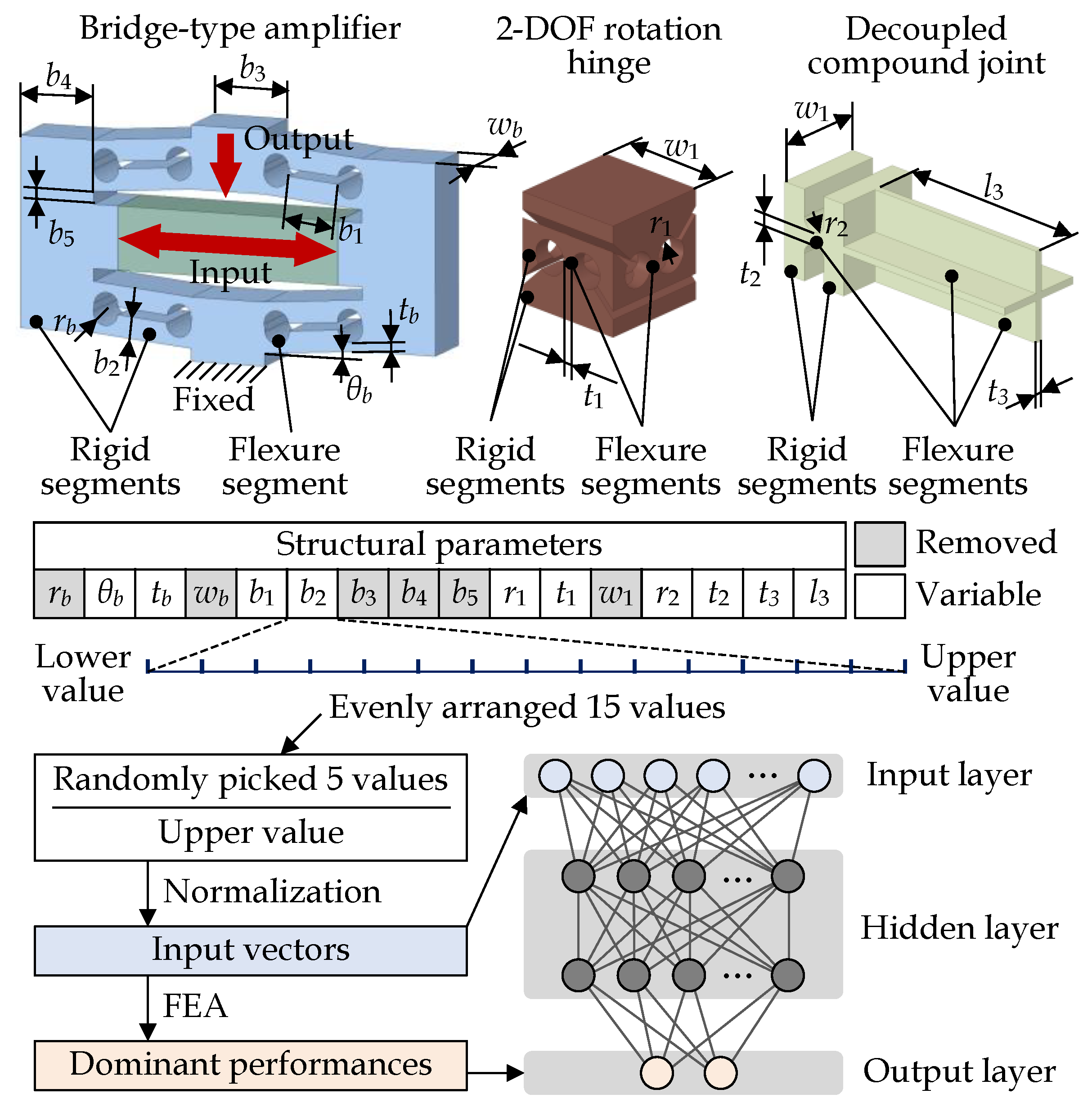
2. Mechanism Design
3. FEA-Based Neural Network Model
4. Characteristic Analysis
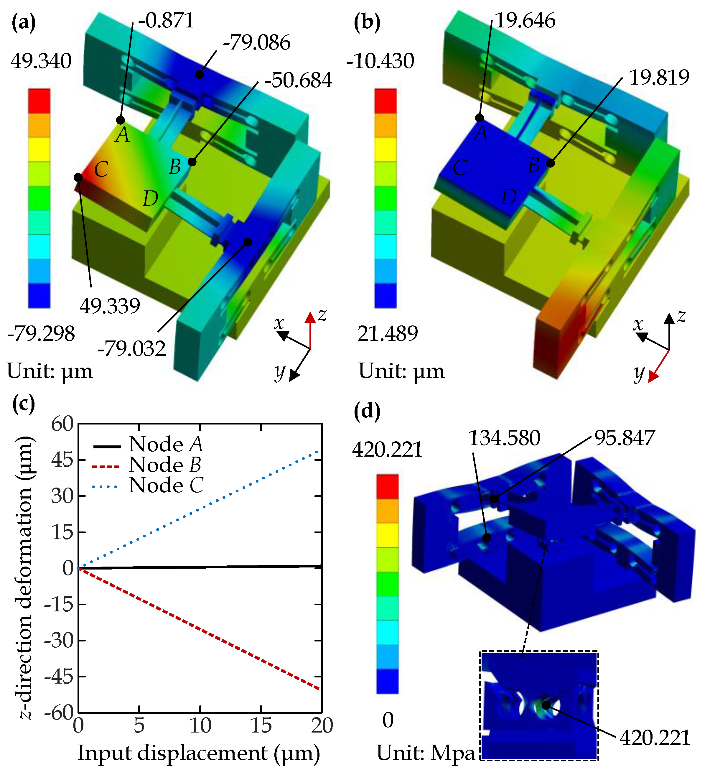
4.1. Static Performances
4.1.1. Static Performances without Load
- (1)
- One-axis actuation
- (2)
- Two-axis actuation
4.1.2. Static Performance Results with Loads
4.2. Dynamic Performances
4.3. Comparisons of Performances with Other Piezo-Actuated Rotation Stages
5. Conclusions
Author Contributions
Funding
Institutional Review Board Statement
Informed Consent Statement
Data Availability Statement
Conflicts of Interest
Abbreviations
| DOF | Degree of freedom |
| FEA | Finite element analysis |
References
- Linghu, C.; Zhang, S.; Wang, C.; Song, J. Transfer printing techniques for flexible and stretchable inorganic electronics. NPJ Flex. Electron. 2018, 2, 26. [Google Scholar] [CrossRef] [Green Version]
- Zhang, S.; Li, S.; Xia, Z.; Cai, K. A review of electronic skin: Soft electronics and sensors for human health. J. Mater. Chem. B 2020, 8, 852–862. [Google Scholar] [CrossRef] [PubMed]
- Tang, X.; Ackerman, M.M.; Shen, G.; Guyot-Sionnest, P. Towards infrared electronic eyes: Flexible colloidal quantum dot photovoltaic detectors enhanced by resonant cavity. Small 2019, 15, 1804920. [Google Scholar] [CrossRef] [PubMed]
- Commault, B.; Duigou, T.; Maneval, V.; Gaume, J.; Chabuel, F.; Voroshazi, E. Overview and perspectives for vehicle-integrated photovoltaics. Appl. Sci. 2021, 11, 11598. [Google Scholar] [CrossRef]
- Zhou, X.; Tian, P.; Sher, C.W.; Wu, J.; Liu, H.; Liu, R.; Kuo, H.C. Growth, transfer printing and colour conversion techniques towards full-colour micro-LED display. Prog. Quantum Electron. 2020, 71, 100263. [Google Scholar] [CrossRef]
- Park, J.; Lee, Y.; Lee, H.; Ko, H. Transfer printing of electronic functions on arbitrary complex surfaces. ACS Nano 2020, 14, 12–20. [Google Scholar] [CrossRef]
- Liang, C.; Wang, F.; Huo, Z.; Shi, B.; Tian, Y.; Zhao, X.; Zhang, D. A 2-DOF monolithic compliant rotation platform driven by piezoelectric actuators. IEEE Trans. Ind. Electron. 2019, 67, 6963–6974. [Google Scholar] [CrossRef]
- Lee, H.J.; Kim, H.C.; Kim, H.Y.; Gweon, D.G. Optimal design and experiment of a three-axis out-of-plane nano positioning stage using a new compact bridge-type displacement amplifier. Rev. Sci. Instrum. 2013, 84, 115103. [Google Scholar] [CrossRef] [Green Version]
- Qu, J.; Chen, W.; Zhang, J.; Chen, W. A piezo-driven 2-DOF compliant micropositioning stage with remote center of motion. Sens. Actuators A Phys. 2016, 239, 114–126. [Google Scholar] [CrossRef]
- Kim, H.; Kim, J.; Ahn, D.; Gweon, D. Development of a nanoprecision 3-DOF vertical positioning system with a flexure hinge. IEEE Trans. Nanotechnol. 2013, 12, 234–245. [Google Scholar] [CrossRef]
- Ling, J.; Ye, T.; Feng, Z.; Zhu, Y.; Li, Y.; Xiao, X. A survey on synthesis of compliant constant force/torque mechanisms. Mech. Mach. Theory 2022, 176, 104970. [Google Scholar] [CrossRef]
- Zhu, B.; Zhang, X.; Zhang, H.; Liang, J.; Zang, H.; Li, H.; Wang, R. Design of compliant mechanisms using continuum topology optimization: A review. Mech. Mach. Theory 2020, 143, 103622. [Google Scholar] [CrossRef]
- Feng, Z.; Liang, W.; Ling, J.; Xiao, X.; Tan, K.K.; Lee, T.H. Precision force tracking control of a surgical device interacting with a deformable membrane. IEEE/ASME Trans. Mechatron. 2022, 27, 5327–5338. [Google Scholar] [CrossRef]
- Bilancia, P.; Berselli, G. An overview of procedures and tools for designing nonstandard beam-based compliant mechanisms. Comput.-Aided Des. 2021, 134, 103001. [Google Scholar] [CrossRef]
- Ling, M.; Howell, L.L.; Cao, J.; Chen, G. Kinetostatic and dynamic modeling of flexure-based compliant mechanisms: A survey. Appl. Mech. Rev. 2020, 72, 030802. [Google Scholar] [CrossRef] [Green Version]
- Chen, W.; Qu, J.; Chen, W.; Zhang, J. A compliant dual-axis gripper with integrated position and force sensing. Mechatronics 2017, 47, 105–115. [Google Scholar] [CrossRef]
- Li, B.; Hao, G. On generating expected kinetostatic nonlinear stiffness characteristics by the kinematic limb-singularity of a crank-slider linkage with springs. Chin. J. Mech. Eng. 2019, 32, 54. [Google Scholar] [CrossRef] [Green Version]
- Yu, Y.Q.; Zhu, S.K. 5R pseudo-rigid-body model for inflection beams in compliant mechanisms. Mech. Mach. Theory 2017, 116, 501–512. [Google Scholar] [CrossRef]
- Šalinić, S.; Nikolić, A. A new pseudo-rigid-body model approach for modeling the quasi-static response of planar flexure-hinge mechanisms. Mech. Mach. Theory 2018, 124, 150–161. [Google Scholar] [CrossRef]
- Holst, G.L.; Teichert, G.H.; Jensen, B.D. Modeling and experiments of buckling modes and deflection of fixed-guided beams in compliant mechanisms. ASME J. Mech. Des. 2011, 133, 051002. [Google Scholar] [CrossRef]
- Ye, T.; Ling, J.; Kang, X.; Feng, Z.; Xiao, X. A novel two-stage constant force compliant microgripper. ASME J. Mech. Des. 2021, 143, 053302. [Google Scholar] [CrossRef]
- Zhang, A.; Chen, G. A comprehensive elliptic integral solution to the large deflection problems of thin beams in compliant mechanisms. ASME J. Mech. Robot. 2013, 5, 021006. [Google Scholar] [CrossRef]
- Chen, G.; Ma, F.; Hao, G.; Zhu, W. Modeling large deflections of initially curved beams in compliant mechanisms using chained beam constraint model. ASME J. Mech. Robot. 2019, 11, 011002. [Google Scholar] [CrossRef]
- Ma, F.; Chen, G. Modeling large planar deflections of flexible beams in compliant mechanisms using chained beam-constraint-model. ASME J. Mech. Robot. 2016, 8, 021018. [Google Scholar] [CrossRef]
- Ma, F.; Chen, G. Bi-BCM: A closed-form solution for fixed-guided beams in compliant mechanisms. ASME J. Mech. Robot. 2017, 9, 014501. [Google Scholar] [CrossRef]
- Chen, G.; Ma, F. Kinetostatic modeling of fully compliant bistable mechanisms using Timoshenko beam constraint model. ASME J. Mech. Des. 2015, 137, 022301. [Google Scholar] [CrossRef]
- Kuo, Y.L.; Lan, C.C. A two-dimensional adjustable constant-force mechanism. ASME J. Mech. Des. 2020, 142, 063304. [Google Scholar] [CrossRef]
- Hanakata, P.Z.; Cubuk, E.D.; Campbell, D.K.; Park, H.S. Accelerated search and design of stretchable graphene kirigami using machine learning. Phys. Rev. Lett. 2018, 121, 255304. [Google Scholar] [CrossRef] [Green Version]
- Bessa, M.A.; Glowacki, P.; Houlder, M. Bayesian machine learning in metamaterial design: Fragile becomes supercompressible. Adv. Mater. 2019, 31, 1904845. [Google Scholar] [CrossRef] [Green Version]
- Liu, F.; Jiang, X.; Wang, X.; Wang, L. Machine learning-based design and optimization of curved beams for multistable structures and metamaterials. Extrem. Mech. Lett. 2020, 41, 101002. [Google Scholar] [CrossRef]
- Farhadi Machekposhti, D.; Tolou, N.; Herder, J.L. A review on compliant joints and rigid-body constant velocity universal joints toward the design of compliant homokinetic couplings. ASME J. Mech. Des. 2015, 137, 032301. [Google Scholar] [CrossRef]


| Parameter | Assigned Value | Parameter | Lower Value | Upper Value |
|---|---|---|---|---|
| a | 12 mm | 0.5 | 8 | |
| 1 mm | 0.2 mm | 1 mm | ||
| 5 mm | 1 mm | 10 mm | ||
| 4 mm | 1.5 mm | 4.5 mm | ||
| 6 mm | 0.5 mm | 1.5 mm | ||
| 1 mm | 0.3 mm | 0.9 mm | ||
| 3.8 mm | 0.5 mm | 1.5 mm | ||
| 0.3 mm | 0.9 mm | |||
| 0.3 mm | 0.9 mm | |||
| 3 mm | 10 mm |
| Item | Density | Poisson’s Ratio | Young’s Modulus | Yield Strength | Tensile Strength |
|---|---|---|---|---|---|
| Parameter | 2.810 | 0.33 | 71.7 | 500 | 570 |
| Unit | g·cm | Gpa | Mpa | Mpa |
| Parameter | Value | Parameter | Value | Parameter | Value |
|---|---|---|---|---|---|
| 3.5 | 0.6 mm | 5.02 mm | |||
| 1.6 mm | 0.6 mm | 0.3 mm | |||
| 0.5 mm | 0.5 mm | 0.3 mm | |||
| 8.2 mm |
| Loads | (Hz) | (Hz) | (Hz) | (Hz) | (Hz) | (Hz) |
|---|---|---|---|---|---|---|
| 0 | 2151.0 | 2154.6 | 2194.7 | 2423.4 | 3175.1 | 3252.2 |
| 2005.1 | 2023.3 | 2169.3 | 2410.4 | 3112.9 | 3127.4 | |
| 1405.8 | 1457.7 | 2170.7 | 2415.0 | 2858.8 | 2866.6 |
Disclaimer/Publisher’s Note: The statements, opinions and data contained in all publications are solely those of the individual author(s) and contributor(s) and not of MDPI and/or the editor(s). MDPI and/or the editor(s) disclaim responsibility for any injury to people or property resulting from any ideas, methods, instructions or products referred to in the content. |
© 2023 by the authors. Licensee MDPI, Basel, Switzerland. This article is an open access article distributed under the terms and conditions of the Creative Commons Attribution (CC BY) license (https://creativecommons.org/licenses/by/4.0/).
Share and Cite
Ye, T.; Li, Y. Synthesis of 2-DOF Decoupled Rotation Stage with FEA-Based Neural Network. Processes 2023, 11, 192. https://doi.org/10.3390/pr11010192
Ye T, Li Y. Synthesis of 2-DOF Decoupled Rotation Stage with FEA-Based Neural Network. Processes. 2023; 11(1):192. https://doi.org/10.3390/pr11010192
Chicago/Turabian StyleYe, Tingting, and Yangmin Li. 2023. "Synthesis of 2-DOF Decoupled Rotation Stage with FEA-Based Neural Network" Processes 11, no. 1: 192. https://doi.org/10.3390/pr11010192