
A Novel Back-Stepping Sliding Mode Control Strategy of Direct-Drive Wave Energy Converters

Abstract
:1. Introduction
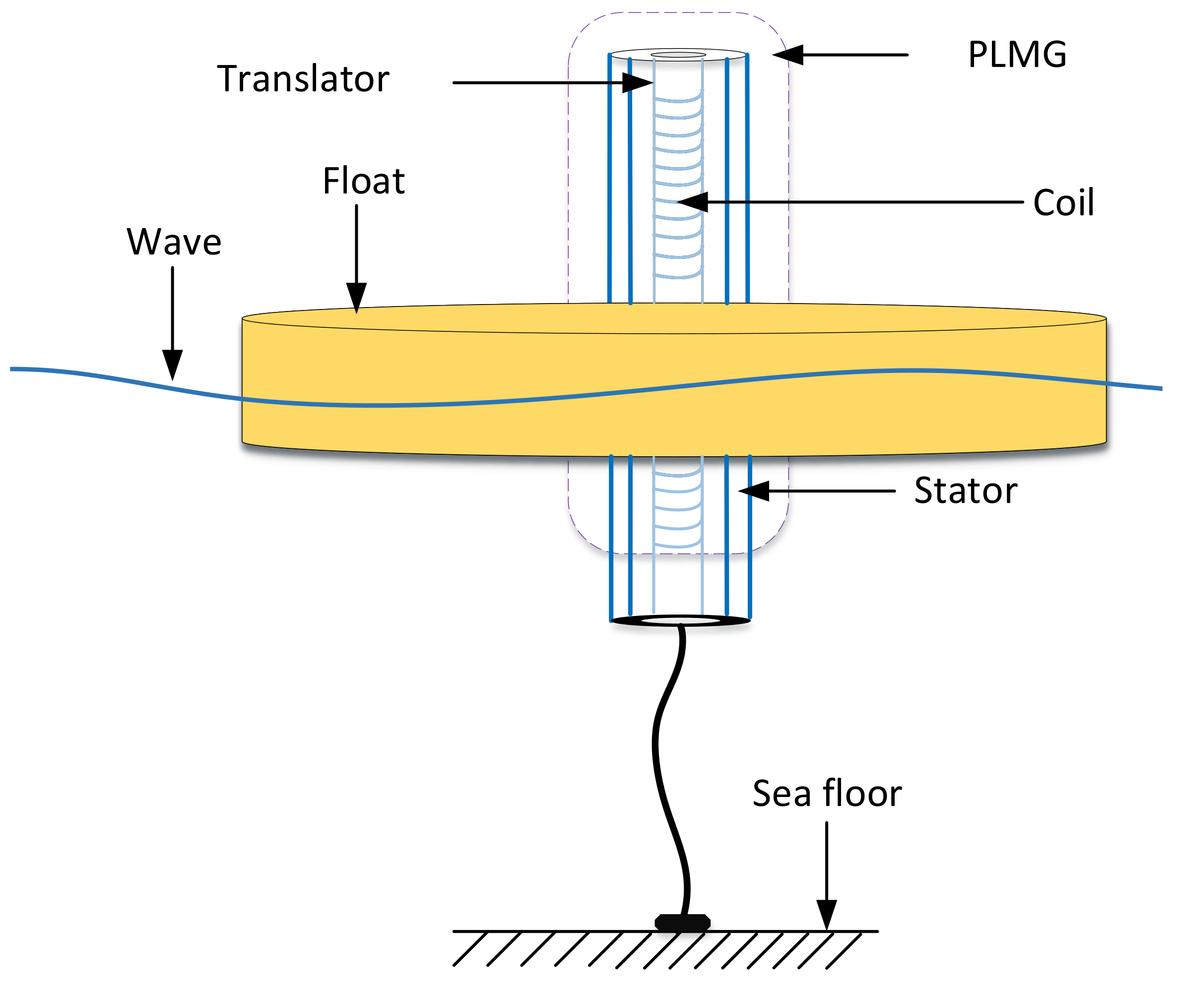
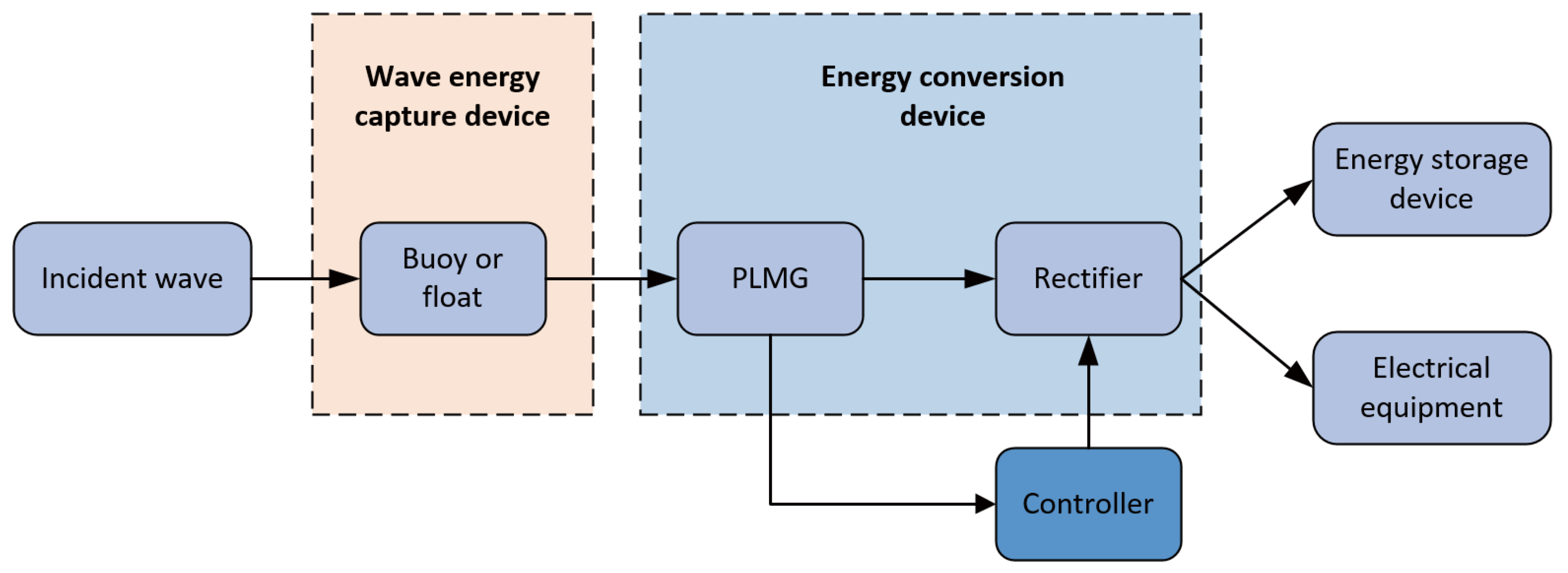
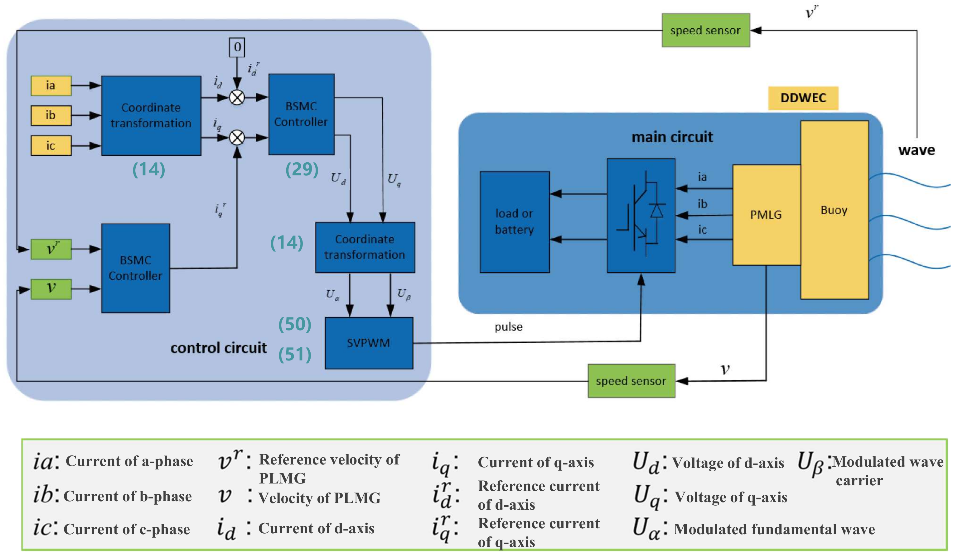
- The entire direct-drive wave energy conversion (DDWEC) system is divided into main and control circuits, whereby the former consists of the float, permanent magnet linear generator (PMLG), rectifier, and load. In this work, we focus on the velocity control of DDWEC, which can be affected by the anti-electromagnetic force of PMLG. By employing a series of axis transformations, the PMLG current signal is changed from the frame of reference to the frame of reference.
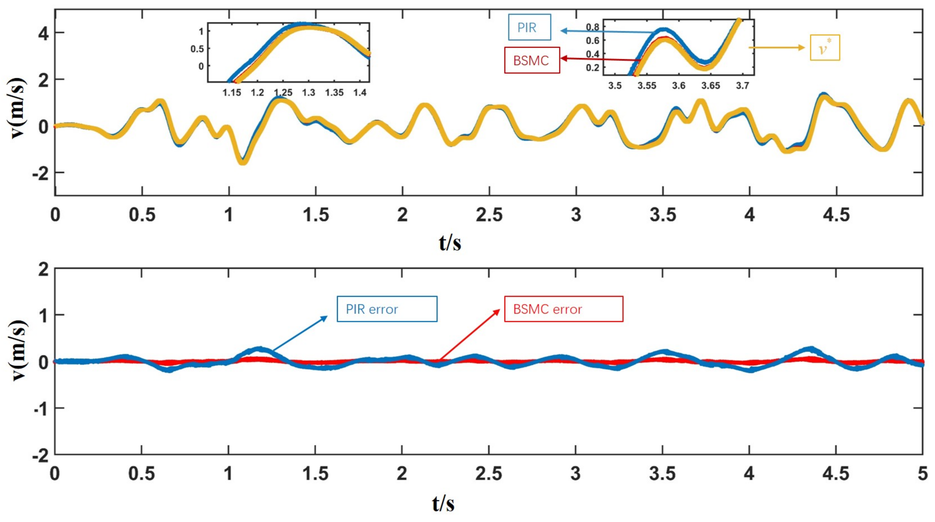
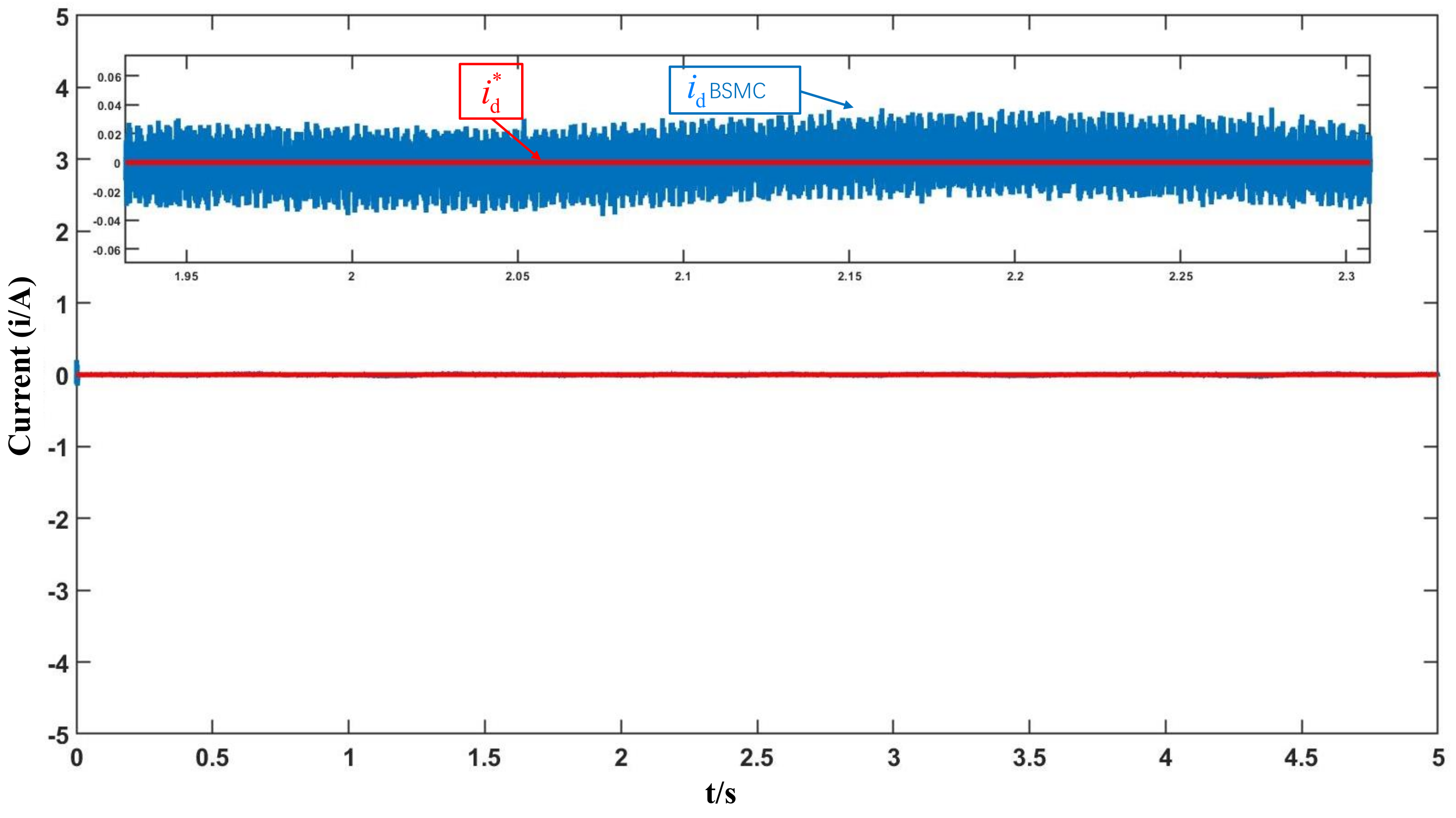
- To facilitate the design of the motor controller, a zero d-axis vector control scheme is selected. Next, a BSMC scheme is designed to use the actual current and reference current of the d-axis and q-axis as inputs of the controller.
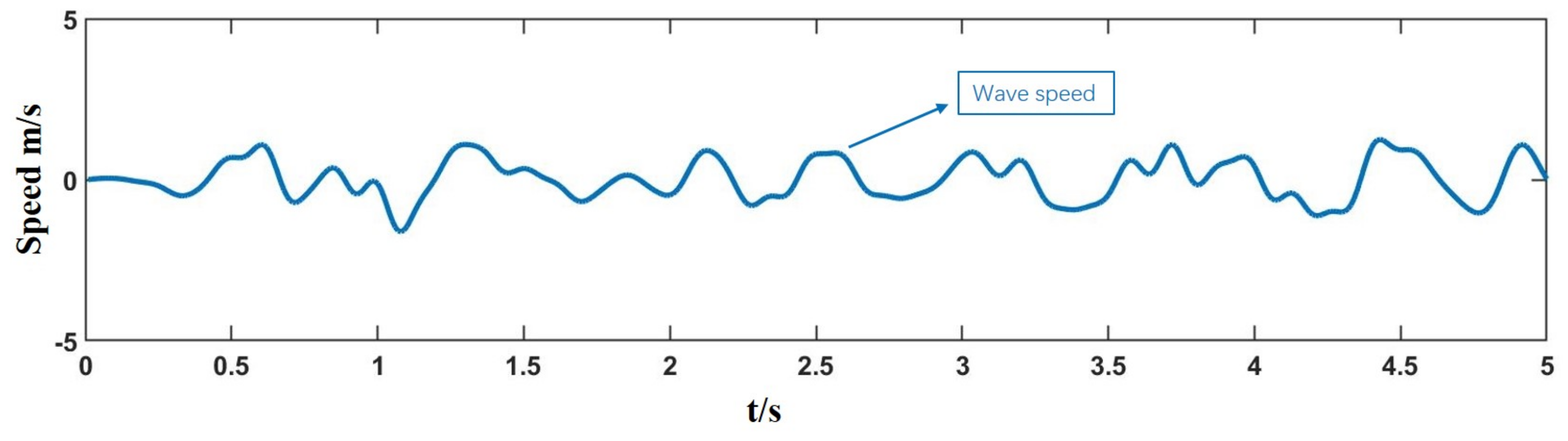
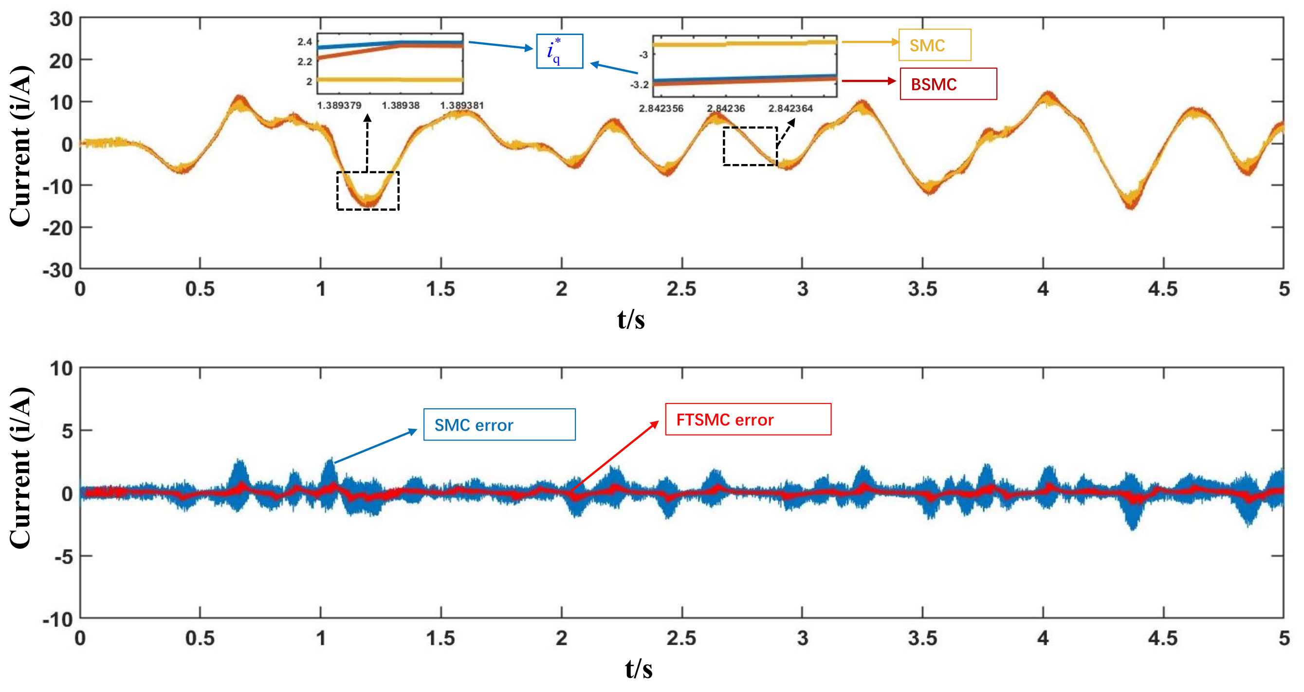
- To accurately and quickly track d-axis and q-axis current signals, control voltage signals of the SVPWM pulse generator are generated. The rectifier circuit is driven by the pulse to work. PMLG’s anti-electromagnetic is affected by the load characteristics of the main circuit, whereby the velocity of PMLG is affected. Eventually, the velocity of PMLG is in phase with the incident wave force. The entire system resonance is reached. The incident wave energy of DDWEC is adsorbed to the utmost.
2. PMLG Dynamic Modeling
Assumption
- (1)
- No damper winding on the mover and permanent magnet.
- (2)
- The effects of saturation, eddy current, hysteresis, and end effects on motor parameters are ignored.
- (3)
- Permanent magnet magnetomotive force remains constant.
- (4)
- The motor stator’s three-phase winding armature resistance and armature inductance are equal.
- (i)
- When , stator flux linkage expression is as follows:
- (ii)
- When , we have
3. Controller Design and Stability Analysis
3.1. Design of
3.2. Design of PMLG Controller
3.2.1. Forward Motion
3.2.2. Reverse Motion
4. Simulation and Discussion
5. Conclusions
Author Contributions
Funding
Institutional Review Board Statement
Informed Consent Statement
Data Availability Statement
Conflicts of Interest
References
- Liu, C.; Zhu, H.; Dong, R. Sensitivity analysis and Optimal design of a linear magnetic gear for direct-drive wave energy conversion. IEEE Access. 2019, 7, 73983–73992. [Google Scholar] [CrossRef]
- Wilkinson, L.; Whittaker, T.J.T.; Thies, P.R. The power-capture of a nearshore, modular, flap-type wave energy converter in regular waves. Ocean Eng. 2017, 137, 394–403. [Google Scholar] [CrossRef]
- Ringwood, J.V.; Bacelli, G.; Fusco, F. Energy-maximizing control of wave-energy converters: The development of control system technology to optimize their operation. IEEE Trans. Syst. Mag. 2014, 34, 30–55. [Google Scholar]
- Antonio, F.O. Wave energy utilization: A review of the technologies. Renew. Sust. Energ. Rev. 2010, 14, 899–918. [Google Scholar]
- Mendonca, H.; Martinez, S. A resistance emulation approach to optimize the wave energy harvesting for a direct drive point absorber. IEEE Trans. Sustain. Energy 2015, 7, 3–11. [Google Scholar] [CrossRef]
- Babarit, A.; Clément, A.H. Optimal latching control of a wave energy device in regular and irregular waves. Appl. Ocean Res. 2006, 28, 77–91. [Google Scholar] [CrossRef]
- Tedeschi, E.; Molinas, M. Impact of control strategies on the rating of electric power take off for wave energy conversion. In Proceedings of the 2010 IEEE International Symposium on Industrial Electronics, Bari, Italy, 4–7 July 2010; pp. 2406–2411. [Google Scholar]
- Shek, J.K.H.; Macpherson, D.E.; Mueller, M.A. Reaction force control of a linear electrical generator for direct drive wave energy conversion. IET Renew. 2007, 1, 17–24. [Google Scholar] [CrossRef] [Green Version]
- Bacelli, G.; Coe, R.G. Comments on control of wave energy converters. IEEE Trans. Contr. Syst. Technol. 2020, 29, 478–481. [Google Scholar] [CrossRef]
- Marei, M.I.; Mokhtar, M.; El-Sattar, A.A. MPPT strategy based on speed control for AWS-based wave energy conversion system. Renew. Energy 2015, 83, 305–317. [Google Scholar] [CrossRef]
- Lopes, M.F.P.; Hals, J.; Gomes, R.P.F. Experimental and numerical investigation of non-predictive phase-control strategies for a point-absorbing wave energy converter. Ocean Eng. 2009, 36, 386–402. [Google Scholar] [CrossRef]
- Neshat, M.; Sergiienko, N.Y.; Mirjalili, S.; Majidi Nezhad, M.; Piras, G.; Astiaso Garcia, D. Multi-mode wave energy converter design optimisation using an improved moth flame optimisation algorithm. Energies 2021, 14, 3737. [Google Scholar] [CrossRef]
- Ciappi, L.; Simonetti, I.; Bianchini, A.; Cappietti, L.; Manfrida, G. Application of integrated wave-to-wire modelling for the preliminary design of oscillating water column systems for installations in moderate wave climates. Renew. Energy 2022, 194, 232–248. [Google Scholar] [CrossRef]
- Ciappi, L.; Cheli, L.; Simonetti, I.; Bianchini, A.; Manfrida, G.; Cappietti, L. Wave-to-wire model of an oscillating-water-column wave energy converter and its application to mediterranean energy hot-spots. Energies 2020, 13, 5582. [Google Scholar] [CrossRef]
- Henriques, J.; Portillo, J.; Sheng, W.; Gato, L.; Falcão, A. Dynamics and control of air turbines in oscillating-water-column wave energy converters: Analyses and case study. Renew. Sustain. Energy Rev. 2019, 112, 571–589. [Google Scholar] [CrossRef]
- Henriques, J.; Gato, L.; Lemos, J.; Gomes, R.; Falcão, A. Peak-power control of a grid-integrated oscillating water column wave energy converter. Energy 2016, 109, 378–390. [Google Scholar] [CrossRef] [Green Version]
- Eltamaly, A.M.; Farh, H.M. Dynamic global maximum power point tracking of the PV systems under variant partial shading using hybrid GWO-FLC. Sol. Energy 2019, 177, 306–316. [Google Scholar] [CrossRef]
- Sangwongwanich, A.; Blaabjerg, F. Mitigation of interharmonics in PV systems with maximum power point tracking modification. IEEE Trans. Power Electron. 2019, 34, 8279–8282. [Google Scholar] [CrossRef] [Green Version]
- Napole, C.; Derbeli, M.; Barambones, O. Fuzzy logic approach for maximum power point tracking implemented in a real time photovoltaic system. Appl. Sci. 2021, 11, 5927. [Google Scholar] [CrossRef]
- Mirza, A.F.; Mansoor, M.; Zhan, K.; Ling, Q. High-efficiency swarm intelligent maximum power point tracking control techniques for varying temperature and irradiance. Energy 2021, 228, 120602. [Google Scholar] [CrossRef]
- Pan, L.; Zhu, Z.; Xiong, Y.; Shao, J. Integral sliding mode control for maximum power point tracking in DFIG based floating offshore wind turbine and power to gas. Processes 2021, 9, 1016. [Google Scholar] [CrossRef]
- Elsonbaty, N.A.; Enany, M.A.; Elymany, M. Proposed rotor field-oriented maximum power point tracking polices for permanent magnet synchronous generator-based wind turbine. Wind Eng. 2021, 45, 973–991. [Google Scholar] [CrossRef]
- Amon, E.A.; Brekken, T.K.; Schacher, A.A. Maximum power point tracking for ocean wave energy conversion. IEEE Trans. Ind. Appl. 2012, 48, 1079–1086. [Google Scholar] [CrossRef]
- António, F.D.O. Modelling and control of oscillating-body wave energy converters with hydraulic power take-off and gas accumulator. Ocean Eng. 2007, 34, 2021–2032. [Google Scholar]
- Kavya, M.; Jayalalitha, S. A novel coarse and fine control algorithm to improve Maximum Power Point Tracking (MPPT) efficiency in photovoltaic system. ISA Trans. 2022, 121, 180–190. [Google Scholar]
- Nguyen, A.T.; Rafaq, M.S.; Choi, H.H.; Jung, J.W. A model reference adaptive control based speed controller for a surface-mounted permanent magnet synchronous motor drive. IEEE Trans. Ind. Electron. 2018, 65, 9399–9409. [Google Scholar] [CrossRef]
- Zhao, A.; Wu, W.; Sun, Z.; Zhu, L.; Lu, K.; Chung, H.; Blaabjerg, F. A flower pollination method based global maximum power point tracking strategy for point-absorbing type wave energy converters. Energies 2019, 12, 1343. [Google Scholar] [CrossRef] [Green Version]
- Zhan, S.; Li, G.; Na, J.; He, W. Feedback noncausal model predictive control of wave energy converters. Control Eng. Pract. 2019, 85, 110–120. [Google Scholar] [CrossRef]
- Zhan, S.; Li, G.; Bailey, C. Economic feedback model predictive control of wave energy converters. IEEE Trans. Ind. Electron. 2019, 67, 3932–3943. [Google Scholar] [CrossRef]
- Tom, N.; Yeung, R.W. Experimental confirmation of nonlinear-model-predictive control applied offline to a permanent magnet linear generator for ocean-wave energy conversion. IEEE J. Ocean. Eng. 2015, 41, 281–295. [Google Scholar]
- De la Villa-Jaen, A.; El Montoya-Andrade, D.; Garcia-Santana, A. Control strategies for point absorbers considering linear generator copper losses and maximum excursion constraints. IEEE Trans. Sus. Energy 2018, 9, 433–442. [Google Scholar] [CrossRef]
- Pillay, P.; Krishnan, R. Modeling, simulation, and analysis of permanent-magnet motor drives. I. The permanent-magnet synchronous motor drive. IEEE Trans. Ind. Appl. 1989, 25, 265–273. [Google Scholar] [CrossRef]
- Chinchilla, M.; Arnaltes, S.; Burgos, J.C. Control of permanent-magnet generators applied to variable-speed wind-energy systems connected to the grid. IEEE Trans. Energy Convers. 2006, 21, 265–273. [Google Scholar] [CrossRef] [Green Version]
- Polinder, H.; Damen, M.E.C.; Gardner, F. Linear PM generator system for wave energy conversion in the AWS. IEEE Trans. Energy Convers. 2004, 19, 583–589. [Google Scholar] [CrossRef] [Green Version]


| Parameters | Values | Parameters | Values |
|---|---|---|---|
| m | 100 kg | 200 kg | |
| 3500 N | k | 2500 N | |
| 6000 N | g | 9.8 m/s | |
| 1 g/cm | S | 0.39 m |
| Parameters | Values | Parameters | Values |
|---|---|---|---|
| 8.2 mH | 8.2 mH | ||
| 6.28 | 0.147 wb | ||
| 0.05 m | 3.4 mH |
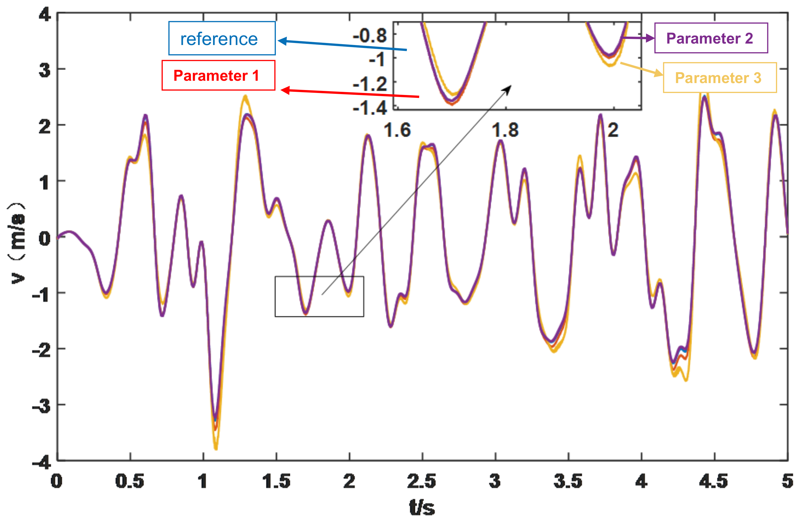
| Parameters | Parameter 1 | Parameter 2 | Parameter 3 |
|---|---|---|---|
| 2 | 3 | 5 | |
| 6 | 8 | 10 | |
| 6 | 8 | 10 | |
| 8 | 10 | 15 | |
| 8 | 15 | 20 | |
| 10 | 15 | 20 | |
Publisher’s Note: MDPI stays neutral with regard to jurisdictional claims in published maps and institutional affiliations. |
© 2022 by the authors. Licensee MDPI, Basel, Switzerland. This article is an open access article distributed under the terms and conditions of the Creative Commons Attribution (CC BY) license (https://creativecommons.org/licenses/by/4.0/).
Share and Cite
Weng, S.; Wang, J. A Novel Back-Stepping Sliding Mode Control Strategy of Direct-Drive Wave Energy Converters. Processes 2022, 10, 1385. https://doi.org/10.3390/pr10071385
Weng S, Wang J. A Novel Back-Stepping Sliding Mode Control Strategy of Direct-Drive Wave Energy Converters. Processes. 2022; 10(7):1385. https://doi.org/10.3390/pr10071385
Chicago/Turabian StyleWeng, Shiguang, and Jianyong Wang. 2022. "A Novel Back-Stepping Sliding Mode Control Strategy of Direct-Drive Wave Energy Converters" Processes 10, no. 7: 1385. https://doi.org/10.3390/pr10071385