Article

Performance Improvement of H8 Transformerless Grid-Tied Inverter Using Model Predictive Control Considering a Weak Grid

1
Electrical Engineering Department, Faculty of Engineering, University of Tabuk, Tabuk 47913, Saudi Arabia
2
Renewable Energy & Energy Efficiency Centre (REEEC), University of Tabuk, Tabuk 47913, Saudi Arabia
3
Mechanical Engineering Department, Faculty of Engineering, University of Tabuk, Tabuk 47913, Saudi Arabia
4
Computer Science Department, Faculty of Computer & Information Technology, Industrial Innovation and Robotics Center, University of Tabuk, Tabuk 47913, Saudi Arabia
5
Department of Electrical Engineering, Faculty of Engineering, Aswan University, Aswan 81542, Egypt
*
Author to whom correspondence should be addressed.
Processes 2022, 10(7), 1243; https://doi.org/10.3390/pr10071243
Submission received: 18 May 2022 / Revised: 17 June 2022 / Accepted: 18 June 2022 / Published: 22 June 2022

Abstract

:
There is increasing utilization of photovoltaic (PV) grid-connected systems in modern power networks. Currently, PV grid-connected systems utilize transformerless inverters that have the advantages of being low cost, low weight, a small size, and highly efficient. Unfortunately, these inverters have an earth leakage current problem due to the absence of galvanic isolation. This phenomenon represents safety and electrical problems for those systems. Recently, the H8 transformerless inverter was introduced to eliminate the earth leakage current. The present study proposes improving the performance of an H8 transformerless inverter using model predictive control (MPC). The inverter was supplied by PV energy and attached to the grid through an LCL filter. During system modeling, the grid weakness was identified. The discrete model of the overall system, including the PV panel, the boost converter, the H8 transformerless inverter, and the controllers, was derived. Then, the introduced H8 transformerless inverter system was simulated and analyzed by the Matlab/Simulink program. The proposed system response using MPC was tested under step disturbances in the PV insolation level. Moreover, the effect of the weak and strong grid operations was considered. The simulation results indicate that the MPC controller has better performance and high-quality injected power. Despite the excellent performance of the strong grid, the nearly weak grid performance is acceptable. Moreover, the Hardware-in-the-Loop (HIL) of the proposed system was implemented using the DSP target LaunchPadXLTMS320F28379D kit to validate the simulation results. Finally, the system performance under the parameter variations showed good robustness.

1. Introduction

Photovoltaic (PV) energy has become one of the most important energy resources in the world. For most countries, solar energy is available in large amounts without being exhausted. Moreover, it has many merits, such as being noise-free, reliable, a long-life, maintenance-free, and it is clean energy [1]. In recent years, the cost of PV systems has decreased to a level that enables their spread worldwide. In addition, rapid advancements in the power electronics field have aided in the development of grid-tied PV systems, which have the advantages of no storage units, good efficiency, and better cost [2].
Grid-tied PV systems have two categories: transformer or transformerless systems. Nevertheless, transformerless grid-connected PV systems are preferred due to their small size, low cost, and high efficiency [3,4,5]. Usually, transformerless grid-tied PV systems have an inverter type called a transformerless inverter. These inverters have different topologies and modulation techniques [6]. However, this type of inverter has some problems, such as lack of galvanic isolation with the grid and the earth leakage current not matching the limitation recommended by the standards [7]. The presence of the leakage capacitance of the PV array and the absence of the galvanic isolation with the grid are the general causes of the earth leakage current. For any transformerless inverter topology, the earth leakage current origin is the inverter’s Common-Mode Voltage (CMV) variations [8]. The problem-solving direction is to reduce the CMV variations or ideally make them constant [9]. This target can be achieved in two ways: either by modifying the inverter topology or by introducing a modulation scheme that limits the CMV variations.
Many topologies and modulation techniques have been introduced for single-phase transformerless inverters [10]. On the other hand, the three-phase transformerless inverters have a higher leakage current and power rating. Hence, fewer attempts have been made to modulate three-phase transformerless inverters [11]. The first attempts were made by references [12,13], where they introduced many modulation schemes for the conventional three-phase topology. However, they concluded that the modulation techniques were not sufficient to reduce the earth leakage current. Hence, introducing new topologies is an important issue in order to eliminate the earth leakage current.
In the literature review, many topologies of the transformerless inverter have been proposed to reduce the earth leakage current [14,15,16,17,18,19,20,21,22,23,24,25,26,27,28]. A simple topology that incorporates 4-arms instead of 3-arms was introduced and tested with some modulation schemes [14,15]. Nevertheless, the supplied power quality and the current total harmonic distortion (THD) were low. Moreover, the control system was complicated. The topologies of the multilevel inverters have been adapted to work in transformerless mode with some modifications and modulation techniques [16,17]. However, the number of switches is high, and the overall system efficiency is low. According to references [18,19,20], the H7 topology is the three-phase version of the single-phase H5 transformerless inverter. There were many modulation schemes suitable for the H7 topology. However, the reduction in the earth’s leakage current was limited. A more recent topology named H8 was introduced [21,22,23,24,25,26]. It consists of the traditional 3-arm transformerless inverter connected to the DC bus via two series power transistors. It may be regarded as the three-phase image of the famous 1-φ H6 transformerless inverter topology. The first proposed H8 inverter topology was created to reduce the Common Mode Voltage (CMV) for electrical drives [21,22]. Then, the idea was used for transformerless PV grid-connected systems. In reference [23], the proposed topology combined the merits of both the AC bypass circuit and DC bypass structures. The results showed a low leakage current and a small THD of the grid current. However, the modulation used was the traditional scheme, and the controller utilized had a low response. The performance of the conventional B6-type voltage source inverter was compared to the H8 topology in [24]. Nevertheless, the efficiency was low, and the system had a poor dynamic response. Reference [25] modified the H8 to obtain zero CMV variations. The technique depended on entering and leaving the zero-voltage vector using a modified configuration and the control scheme. The results of [26] indicated that the H8 topology had better performance than the H7 due to the 50% reduction in CMV amplitude. Hence, the leakage current attenuation improved with the H8 topology. Another version of the H8 inverter called oH8 was proposed [26]. It has been shown that for a given CMV, the parasitic capacitor voltage of oH8, the clamped DC bus version of H8, is higher than that of H8. Hence, the leakage current of oH8 would be higher than for the H8 topology.
Another common problem for grid-connected inverters is the restriction of the grid’s weakness. It is recommended in the standards of the distributed generation system that the grid-connected inverters should be tied to power systems that have Short-Circuit Ratio (SCR) >20, which corresponds to a grid impedance of 5% [27,28]. The grid-tied inverters act stably with the power system when the SCR is kept within the previous range. However, the spread of distributed renewable energy resources with long transmission lines causes the utility grid to possess weak grid performance. The power system is considered to be weak if SCR < 3 [29]. Moreover, the voltage at the Point of Common Coupling (PCC) should be kept at a low harmonic content to avoid voltage distortion problems at the PCC. Hence, the grid-tied inverter should be designed to supply current with a high harmonic rejection and satisfy the standard limitations on the injected grid current [30].
Recently, a major focus has been given to the promising control technique, Model Predictive Control (MPC). It has been adapted for the control of the grid tide inverters [31]. Perfect response and simple implementation are the great merits of the MPC controller. It has been applied to control 3-level transformerless inverters to minimize the earth leakage current [32]. However, the proposed system is complex. The MPC control technique has been adapted for neutral point clamped inverters [33]. Though the earth leakage current is reduced, the proposed system efficiency is lower.
In this research paper, a PV energized H8 transformerless inverter that utilizes the MPC scheme as a controller is introduced. A boost converter was attached to the PV terminals to ensure the Maximum Power Point Tracking (MPPT) operation. The output of the boost converter was the DC bus of the power system. It must be controlled to be constant at a certain designed value to achieve whole system stability and ensure power balance. The H8 transformerless inverter was supplied by the DC bus and tied to the grid using an LCL filter to minimize the injected harmonics. As the MPC algorithm relies mainly on the system discrete model, the whole system model was derived. The LCL filter and the grid weakness characteristics were represented by the grid internal impedance determined by the model. Hence, the MPC control scheme was applied to the H8 transformerless inverter. Then, the introduced system was simulated and analyzed using the Matlab/Simulink platform. The proposed system response using the MPC was tested under step disturbances in the PV insolation level. Moreover, the effects of the nearly weak and strong grid operations were considered. The simulation results indicate that the MPC controller has better performance and high-quality injected power. Despite the excellent performance of the strong grid, the nearly weak grid performance is also acceptable. The objectives of this research are to:
  • Apply the MPC algorithm to the H8 transformerless inverter.
  • Investigate the system discrete model including the LCL filter.
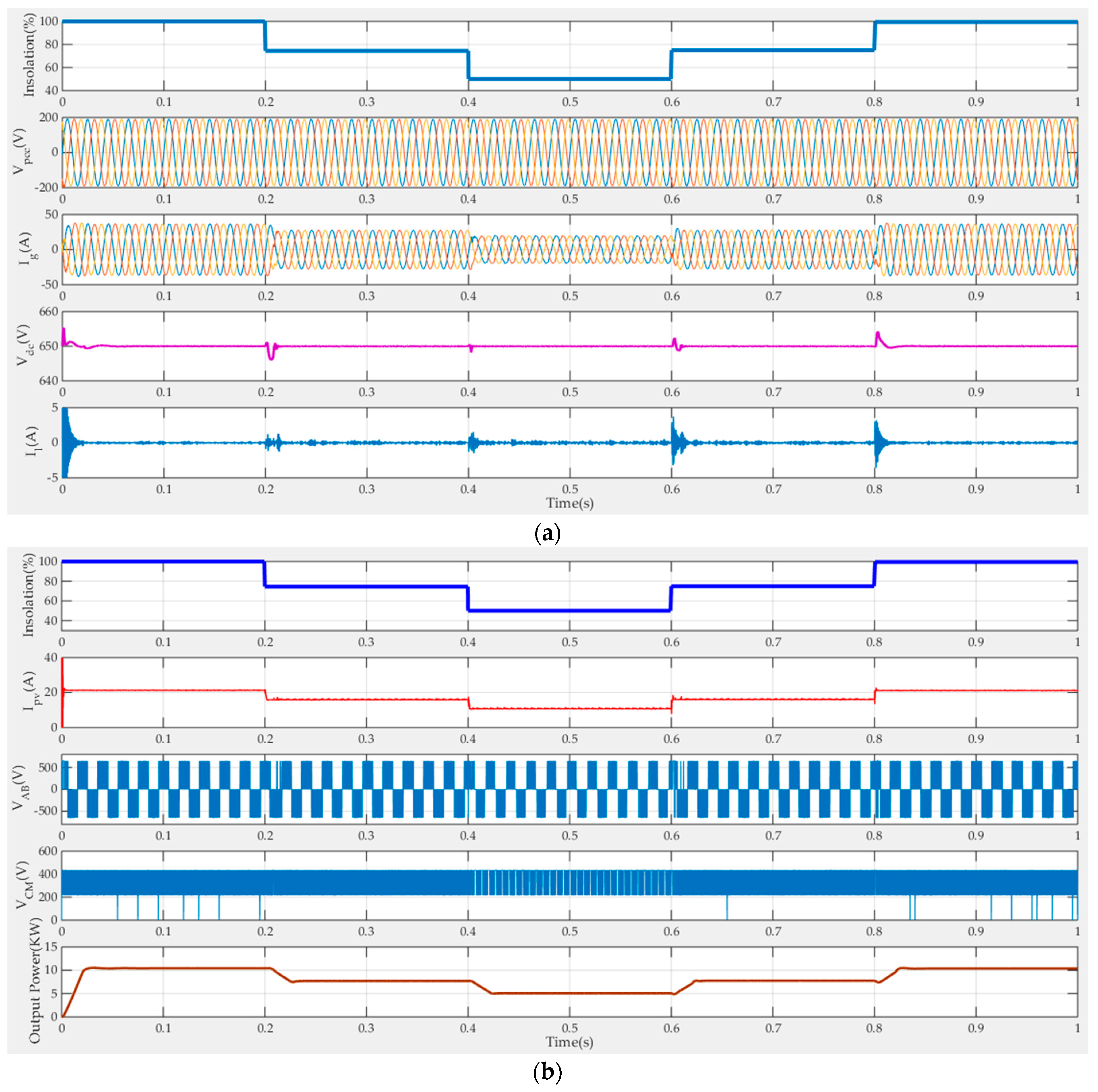
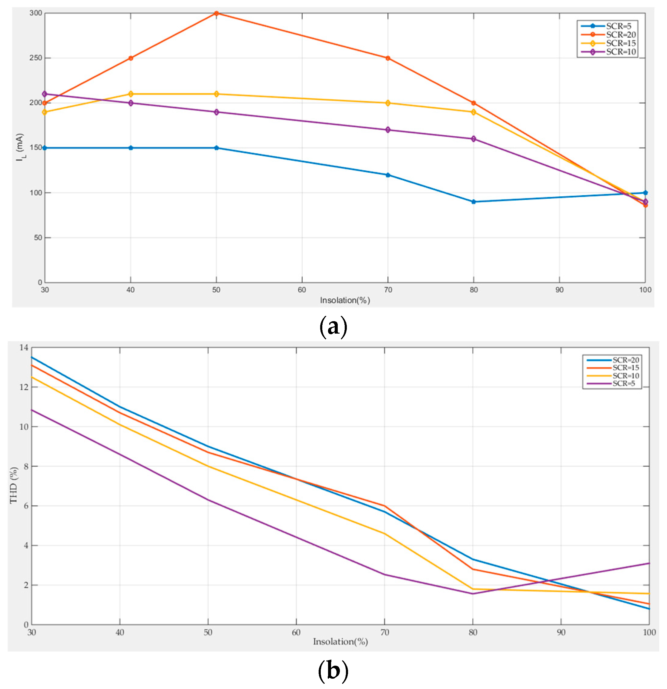
  • Discuss the effects of the grid weakness on the system response.
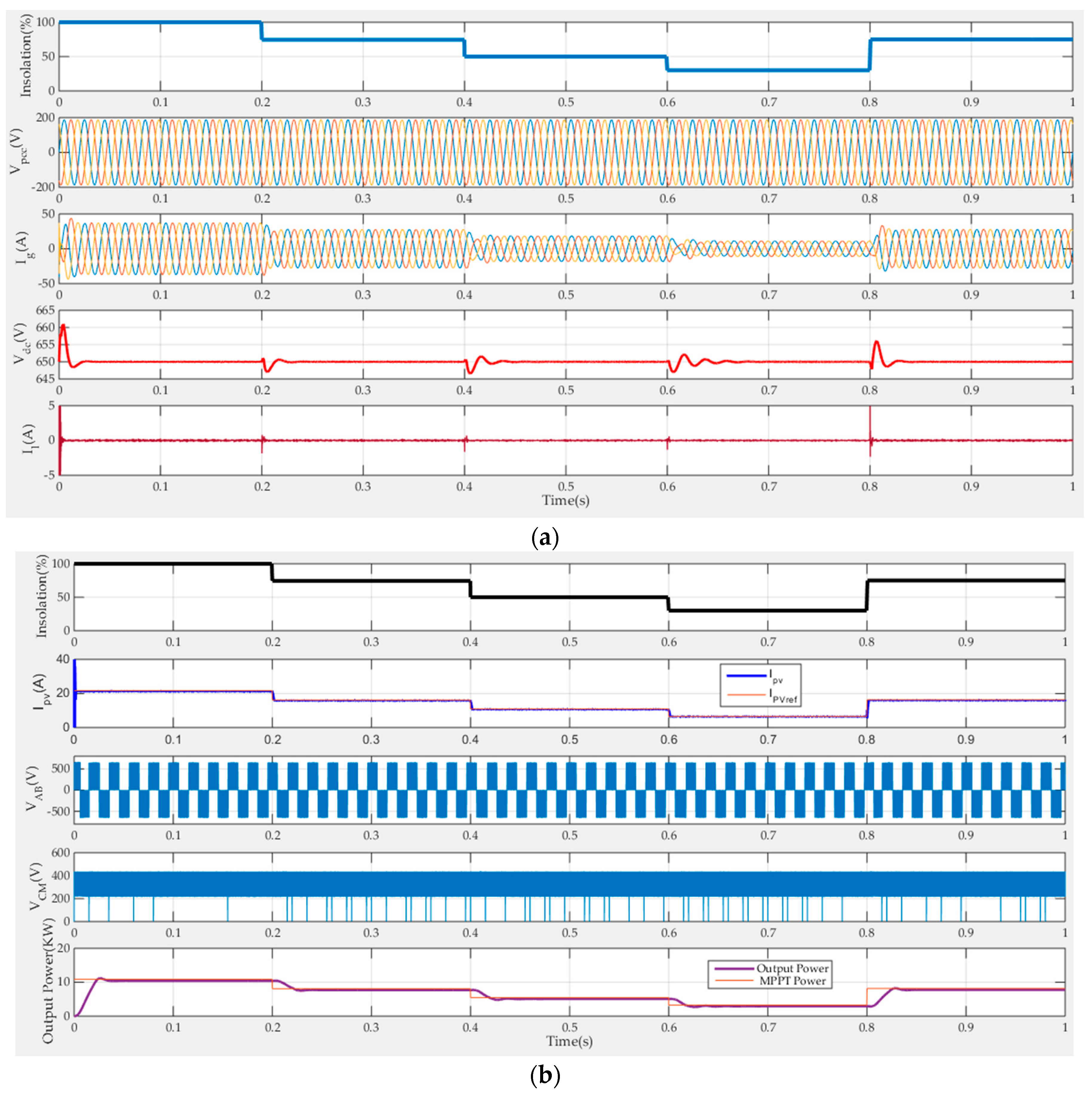
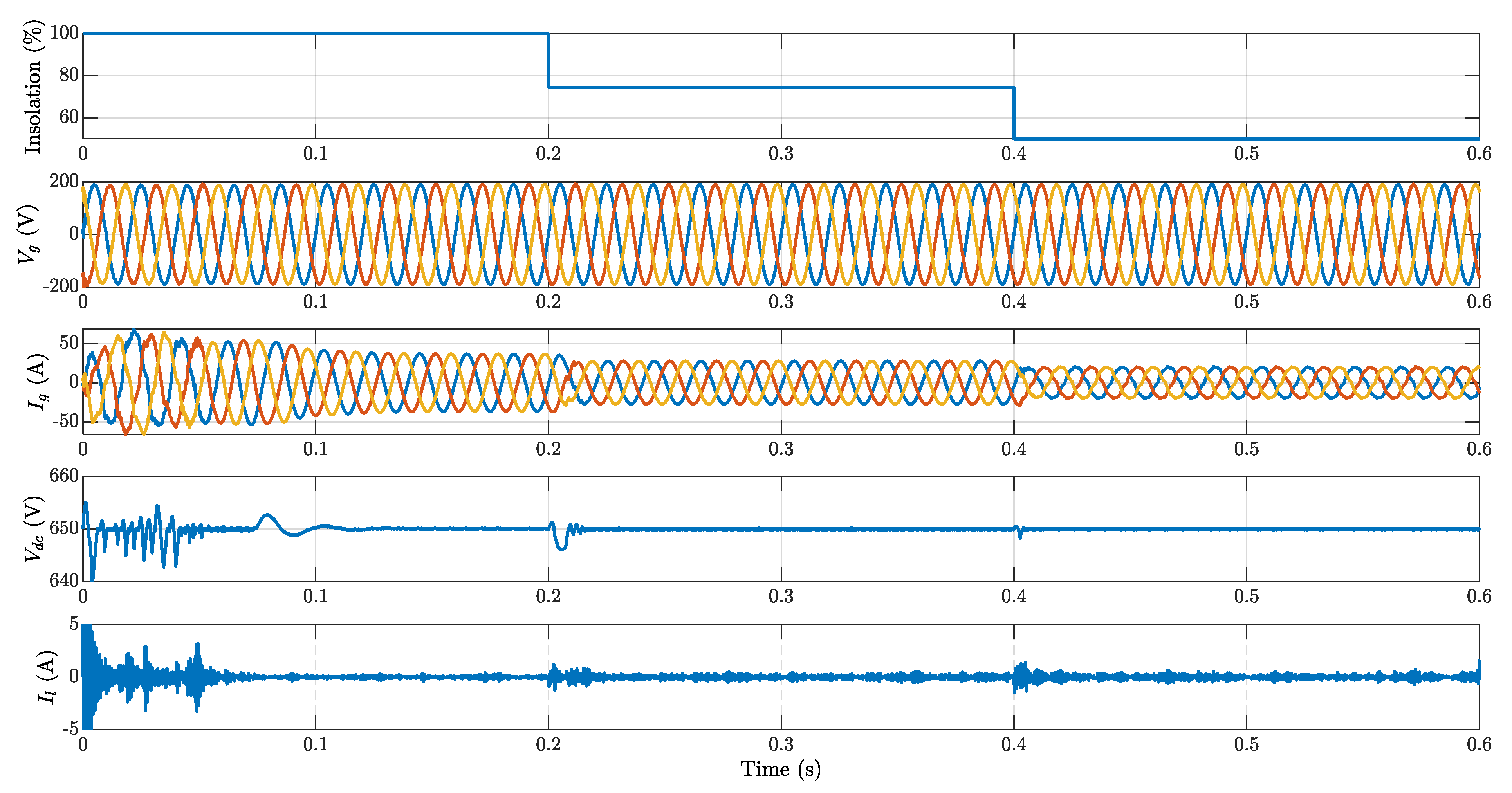
  • Study the system response, under the disturbances in the insolation level.
  • Test the robustness of the system performance against the parameter variations.
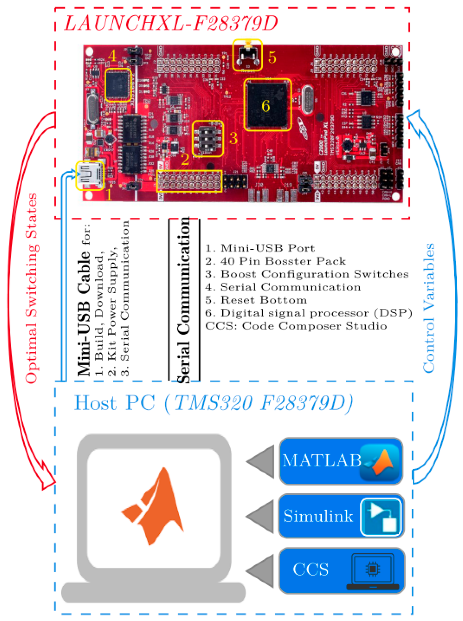
  • Implement the proposed system using the HIL validation technique.
The arrangement of the paper is as follows: Section 2 explains the topology and operation of the H8 Transformerless Inverter. Section 3 demonstrates the MPC of the H8 Transformerless Inverter. The system controllers are described in Section 4. Section 5 introduces the weak grid operation of the H8 transformerless inverter. The simulation results are discussed in Section 6, while the paper’s conclusions are provided in Section 7.

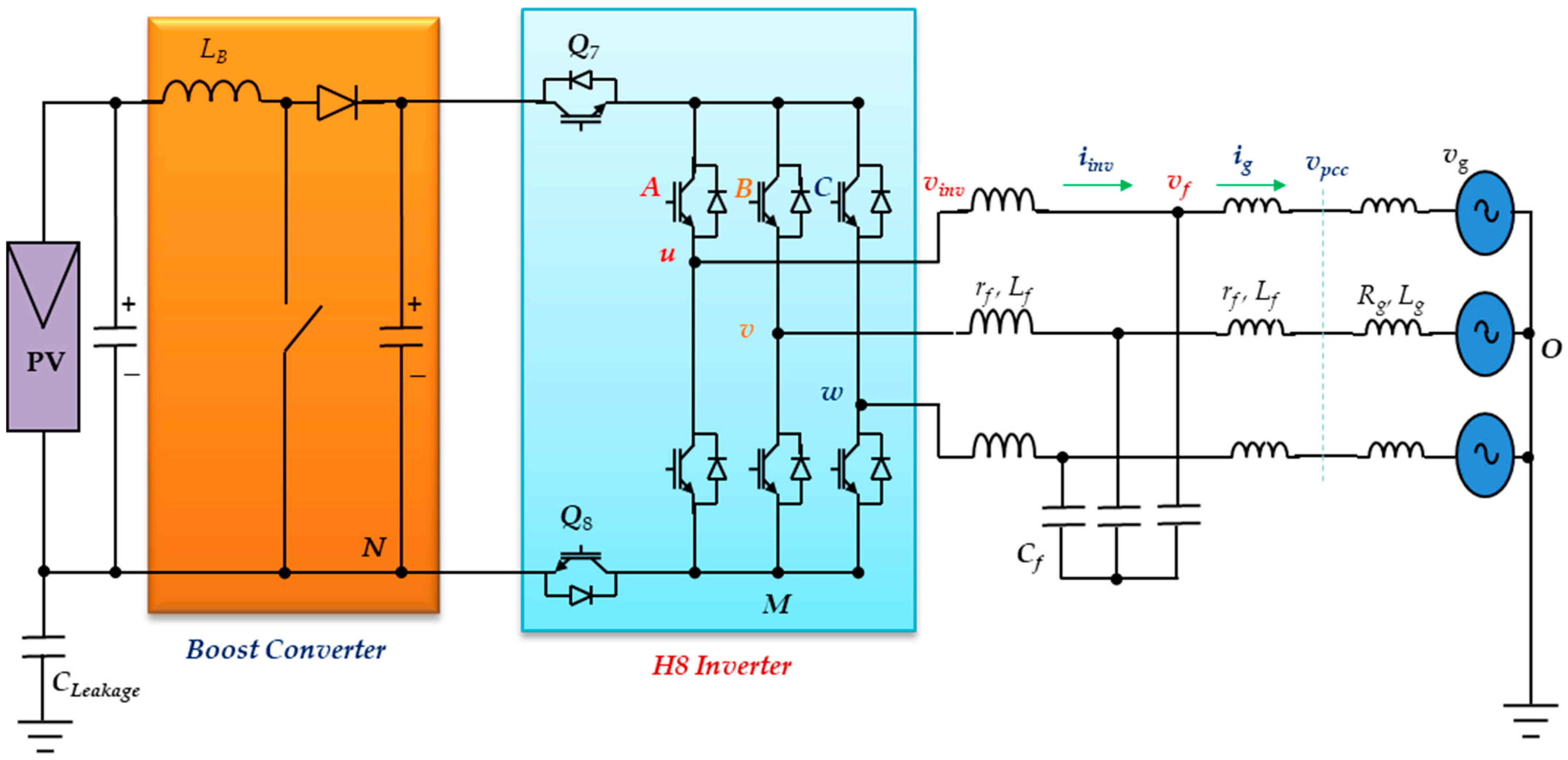
2. H8 Transformerless Inverter Structure and Operation

Figure 1 presents the power circuit of the introduced system. It was a PV-powered grid-connected H8 transformerless inverter. The PV array represented the power generator for the system. The output of the array was attached to a boost converter. It was used to implement the MPPT conditions for the PV array. The output of the boost converter was the system DC bus that feeds the H8 transformerless inverter. The H8 transformerless inverter may be considered as the 3-φ version of the 1-φ H6 transformerless inverter. Its power circuit had eight switches, as shown in Figure 1. It was introduced to reduce the earth leakage current in the grid-connected systems. The topology of the H8 inverter was formed by adding two additional switches, (Q7 and Q8). Their function was to decouple the inverter from the PV during the freewheeling periods of the inverter. Hence, there was no path for an earth leakage current. The H8 transformerless inverter acted as a 3-φ two-level inverter. Therefore, it had eight switching states or voltage vectors ( V ¯ 0 , V ¯ 1 , V ¯ 2 , V ¯ 3 , V ¯ 4 , V ¯ 5 , V ¯ 6 , and V ¯ 7 ). The inverter operating voltage vector depended on the controller objectives. The decoupling switches (Q7 and Q8) were on together for all active voltage vectors. Nevertheless, during the null voltage vectors, the decoupling switches (Q7 and Q8) were modulated according to the following switching functions [25]:
Q 7 = Q 8 = A B ¯ + B C ¯ + C A ¯ ,  
where (A, B, and C) were the logic states of the inverter upper switches.
The configurations of the H8 transformerless inverter for different switching states of the inverter are shown in Figure 2.

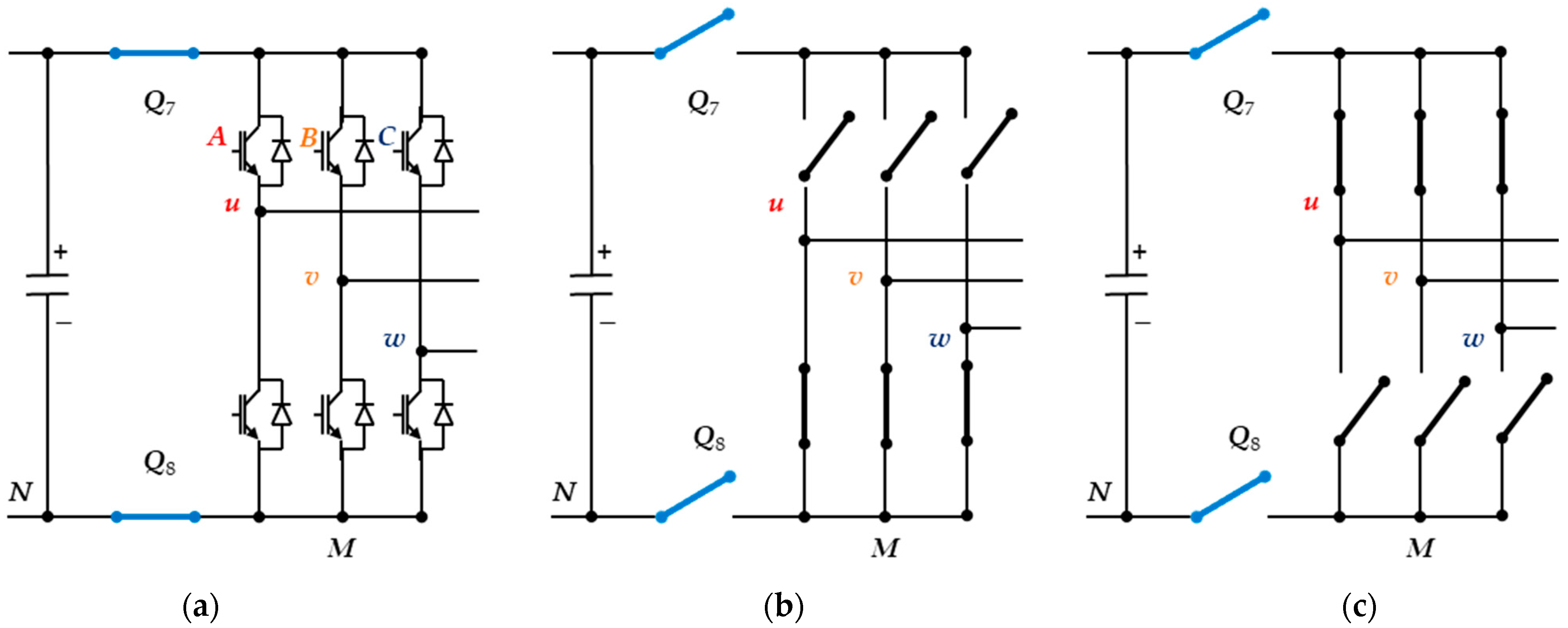
2.1. CMV Model of the H8 Transformerless Inverter

In this section, the CMV of the H8 inverter is analyzed. The CMV variations of the grid-connected inverters must be minimized or ideally constant. The H8 inverter CMV depends on its terminal voltages (VuN, VvN, and VwN,); they can be calculated as follows [20]:
V C M V = V u N + V v N + V w N 3     V C M V = V u M + V v M + V w M 3 + V M N .
However, the H8 inverter terminal voltages and the voltage VMN depend on the operating voltage vector or switching state. Based on the switching state, the corresponding CMV value can be determined as shown in Table 1. This can be summarized as follows:
  • For the active voltage vectors ( V ¯ 1 ,   V ¯ 3 ,   and   V ¯ 5 ), the switches Q7 and Q8 are on. Hence, the voltage VMN is zero. Hence, the CMV is Vdc/3.
  • For the active voltage vectors ( V ¯ 2 ,   V ¯ 4 ,   and   V ¯ 6 ), the switches Q7 and Q8 are on. Hence, the voltage VMN is zero. Hence, the CMV is 2Vdc/3.
  • For the zero voltage vectors ( V ¯ 0 ,   and   V ¯ 7 ), the switches Q7 and Q8 are off. Hence, the voltage VMN is not zero and can be determined for each case. Finally, the CMV equals 2Vdc/3 for V ¯ 7 and it equals Vdc/3 for V ¯ 0 .
Therefore, the levels of the CMV of the H8 inverter were limited to ( 1 3 V d c   and   2 3 V d c ). However, the CMV was limited to ( 1 3 V d c , 2 3 V d c ,   and   V d c ) for the recent inverter H7 [20]. Consequently, the peak variations of the CMV were reduced, which decreased the leakage current. The idea behind this improvement is the disconnection of the PV from the grid during the freewheeling periods using the switches Q7 and Q8.

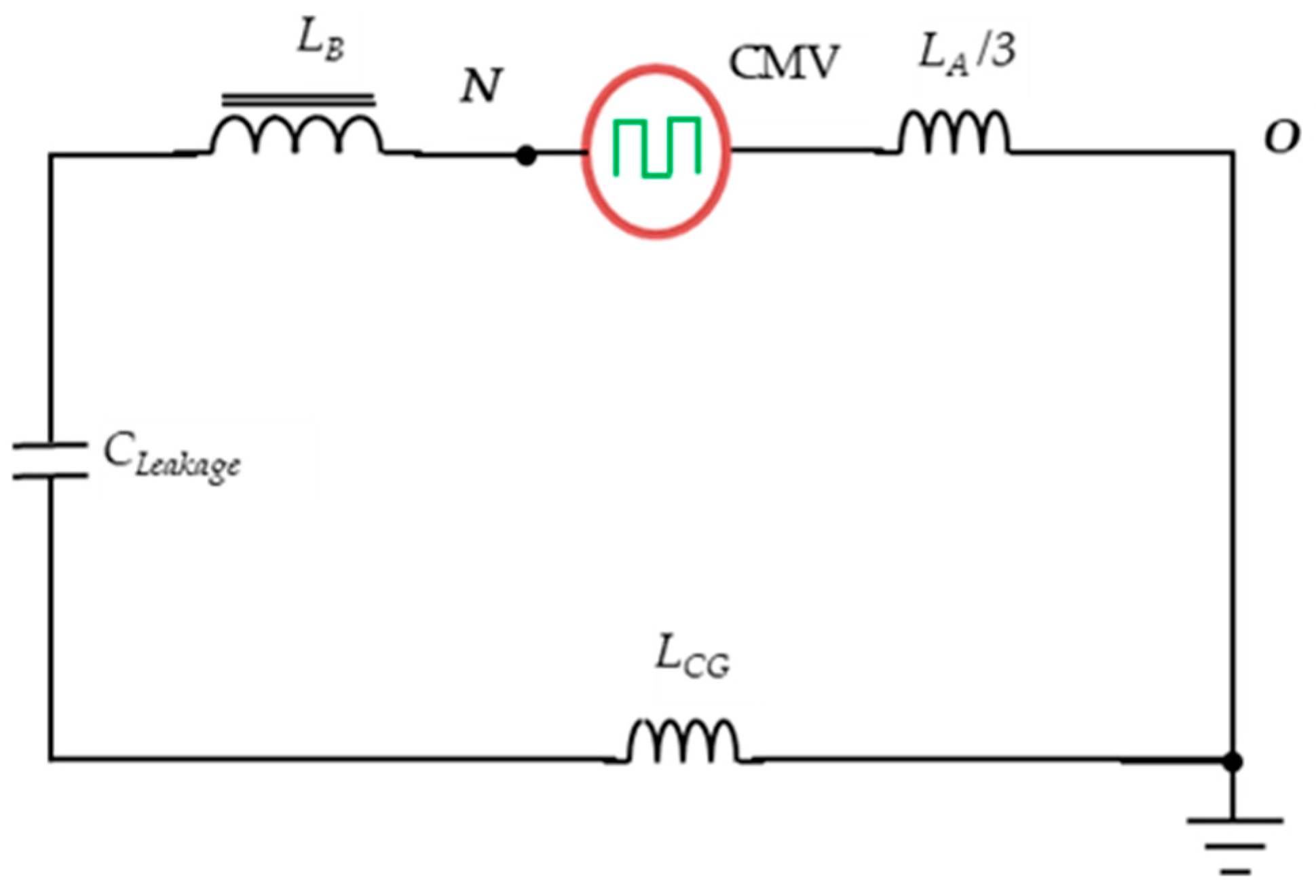
2.2. Earth Leakage Current Path of the H8 Transformerless Inverter

Figure 3 shows the earth leakage current path the of H8 transformerless inverter with the PV panel [20]. The circuit indicates that the CMV source should be alternating for the earth leakage current to flow. Hence, if the CMV variations remain limited, the serious leakage current will be greatly reduced. The instantaneous CMV is conditional on the switching modulation of the H8 transformerless inverter. Consequently, introducing a new modulation strategy that can reduce the CMV will aid the leakage current reduction. Moreover, the H8 transformerless inverter control technique affects the inverter modulation, which will reduce the leakage current reduction.
The H8 transformerless inverter controller may be either a one-shot controller or a modulator-based controller. In the one-shot controller, the inverter switching states are produced directly from the control algorithm, such as the MPC. However, the modulator-based controller must have a modulator to generate the inverter switching states. Hence, the modulation technique must be selected from the commonly known (SPWM, SVPWM, etc.).

3. Model Predictive Control of the H8 Transformerless Inverter

The basic structure of the MPC controller for a certain system is based on the system’s discrete-model. Hence, the starting point in planning the MPC controller is the investigation of the discrete model of the system. Applying Kirchhoff lows to the inverter output filter shown in Figure 1, we have:
[ L g f ( d I ¯ g d t ) L f ( d I ¯ i n v d t ) C f ( d V ¯ C d t ) ] = [ V ¯ c V ¯ g V ¯ i n v V ¯ c I ¯ f I ¯ g ] ,   L g f = L g + L f ,  
where ( I ¯ g ,   V ¯ g ) are the grid current and voltage space vectors, ( V ¯ f ) is the filter capacitor space voltage vector, ( I ¯ i n v ) is the inverter current space vector, ( V ¯ i n v ) is the inverter space vector voltage, (Rg, Lg) is the grid impedance, (rf, Lf) are the filter inductor parameters, and (Cf) is the filter capacitance.
The state-space form of Equation (3) is:
[ d I ¯ g d t d I ¯ i n v d t d V ¯ f d t ] = [ ( R g + r f ) L g f 0 1 L g f 0 r f L f 1 L f 1 C f 1 C f 0 ] [ I ¯ g I ¯ i n v V ¯ f ] + [ 0 1 L f 0 ] V ¯ i n v + [ 1 L g 0 0 ] V ¯ g .
This may be simplified as:
d Y ¯ d t = α Y ¯ + β V ¯ i n v + γ V ¯ g ,
where the state vector ( Y ¯ ) and the constant matrices (α, β, and γ) are defined as:
Y ¯ = [ I ¯ g I ¯ i n v V ¯ f ] ,   α = [ ( R g + r f ) L g f 0 1 L g f 0 r f L f 1 L f 1 C f 1 C f 0 ] , β = [ 0 1 L f 0 ] , γ = [ 1 L g 0 0 ] .
We assumed that the sampling period was (T). The model input was the inverter space voltage vector, and the DC link voltage was considered the disturbance. Hence, the continuous state-space model of Equation (5) can be transformed into the discrete-time state-space model using the backward Euler technique [34]. Although the forward Euler method requires an extra computation at each iteration, the backward Euler method has great stability properties, and its local truncation error is much smaller than using the forward Euler method [35]. Therefore:
Y ¯ ( k + 1 ) = e α T Y ¯ ( k ) + 0 T e α τ β d τ V ¯ i n v + 0 T e α τ γ d τ V ¯ g .
Hence, the discrete model of the H8 transformerless inverter was obtained using Equation (7). The algorithm of the MPC utilizes the discrete model to predict the controlled quantities at the next sample. For all possible switching states, a cost function was built and calculated to select the voltage vector that gives the minimum error. The introduced cost function (g) is:
g = ( i g α i g α * ) 2 + ( i g β i g β * ) 2 ,  
where (i, i) are the α-β compositions of the grid current, and (i*, i*) are the reference α-β compositions of the grid current.

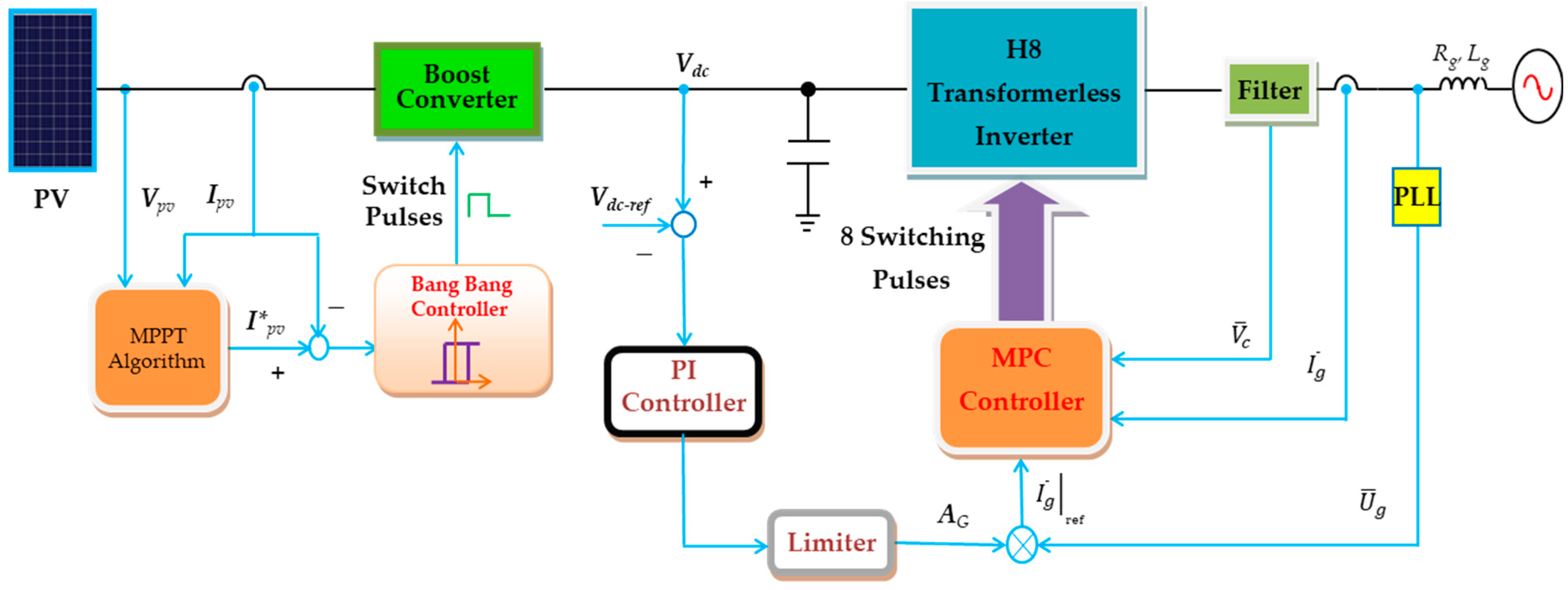
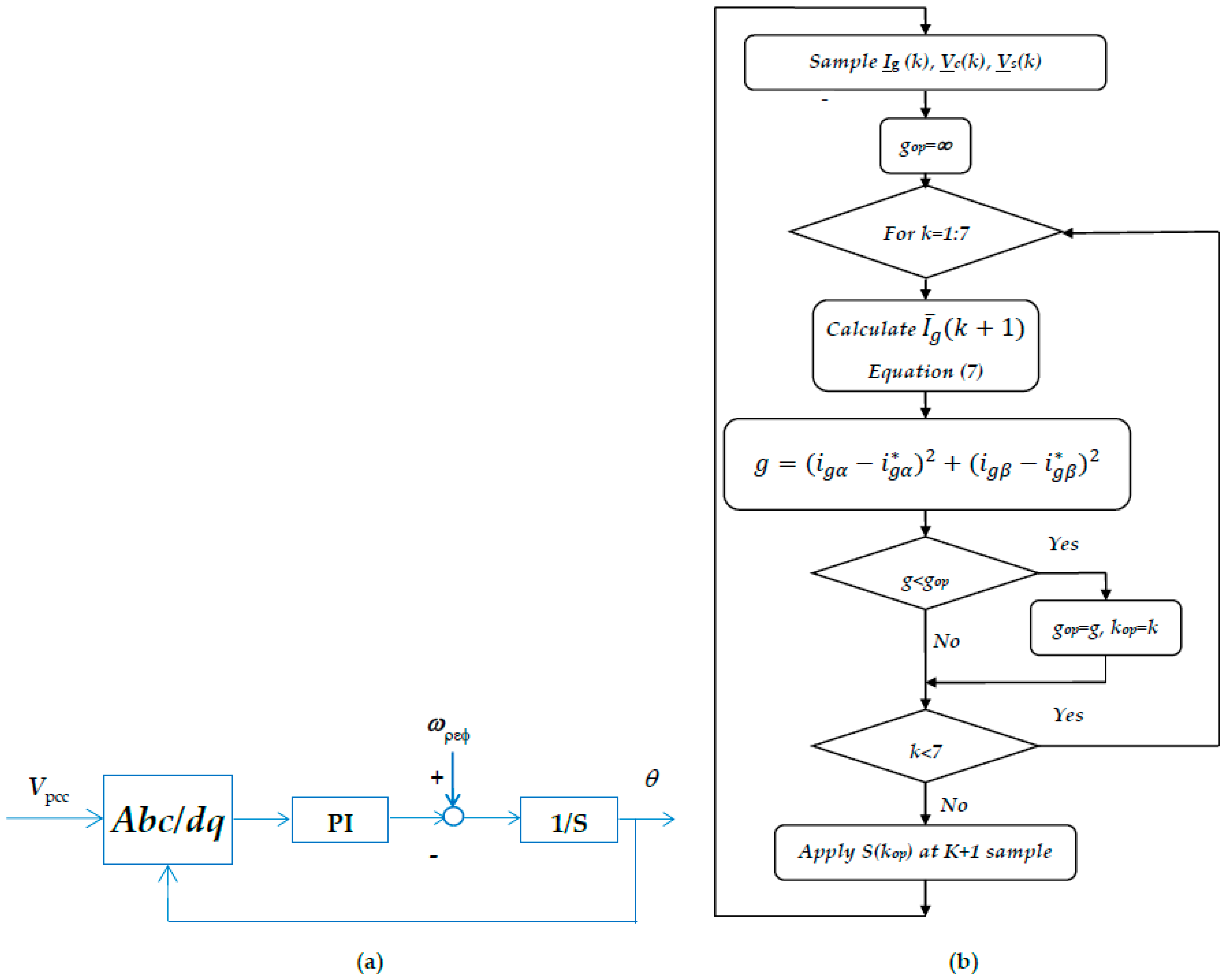
4. System Controllers

A single-line diagram of the proposed system incorporating the system controllers is shown in Figure 4. It had two main controllers namely the power and the H8 transformerless inverter controllers. The power controller included two controllers called the MPPT and the DC-link voltage controllers. As the set point of the DC link controller was constant, the PID controller would be the best choice due to its high stability and good performance for constant set point systems [36]. However, the set point of the H8 transformerless inverter controller was sinusoidal. Hence, the PI was not suitable, and the MPC controller was adapted. To ensure stability, the MPC response, the controller of the inner loop, should be faster than the DC link controller (PID). These controllers are discussed in detail in the next paragraphs. The whole control system is demonstrated in the following subsections.

4.1. Power Controller

The system incorporated two controllers, the MPPT controller and the DC-link voltage controller. The MPPT controller was utilized to take out the peak power from the PV panel. Therefore, it improved the system utilization. The idea was to control the boost converter input current by regulating the converter duty cycle. The controller type was bang-bang with a ±5% band. The reference current was generated by the MPPT algorithm unit, the incremental conductance [16]. That unit measured the instantaneous PV current and voltage and output the reference current for the MPPT controller.
The DC-link voltage controller forced the Vdc to track its reference. This controller regulated the power transfer from the PV to the grid. Its reference voltage value was recommended by the system design values, 650 V for the proposed system [20]. The controller output the reference current for the H8 transformerless inverter. A simple Proportion Integral Derivative (PID) controller was employed. Its output (AG) and action are represented for discrete operation using:
A G ( z ) = [ k P + k I T z z 1 + k D z 1 T z ] e ( z ) ,
where e(z) is the error signal, and ( k P , k I ,   and   k D ) are the PID controller gains. Those gains are tuned using the Ziegler-Nichols technique. This tuning algorithm may be implemented using the next sequence [37]:
  • Let the integral part be zero and decrease the proportional part to a very small value.
  • Increase the proportional part until the output oscillates.
  • Measure the period of oscillation (Ts) and the corresponding proportional gain (Kcp). Hence, the PI controller gains are calculated using:
KP = 0.35 Kcp and KI = 0.8 KP/Ts

4.2. H8 Transformerless Inverter Controller

The H8 transformerless inverter is a current-controlled voltage source inverter. It has a controller that regulates its output current Ig to be AC, which is compatible with the grid voltage and frequency. Moreover, the output current should be supplied at the unity power factor. This controller utilized the MPC scheme to achieve its goals. The MPC controller output was the optimum switching state for the H8 transformerless inverter. Finally, it produced the H8 inverter switches’ pulses. The algorithm of the MPC technique was essentially a discrete control. At startup, the system variables were measured. Then, with the help of the system model, the system variables for the next samples were predicted to optimize the system response. The optimization process for the H8 transformerless inverter was to select the switching state that forced the errors in the controlled variables as close as possible to zero. To accomplish the switching state optimization, an optimization function, sometimes called the cost function, was calculated for each switching state. The switching state that provided the minimum value of the cost function was considered the optimal state and was sent to the converter switches in the following sample. The cost function was adapted to minimize the error in the grid current, which was a 3-φ of zero phase shift with the grid voltage reference generated by a Phase Locked Loop (PLL). The most commonly used PLL for weak grid systems is the Synchronous Reference Frame (SRF) PLL. A block diagram of the SRF PLL is shown in Figure 5a. The PLL measures the grid voltage at the PCC, which may be distorted due to the grid’s internal impedance [30]. It generates 3-φ signals ( U ¯ g ) synchronized to the ideal grid voltages with unity amplitude. The reference currents ( I ¯ g | r e f ) for the MPC controller were generated by multiplying the PLL output signal with the reference amplitude (AG) produced by the DC-link controller output.
I ¯ g | r e f ( k ) = A G U ¯ g ( k ) ,
where (k) is the order of the sample. A flowchart for the MPC algorithm is presented in Figure 5b.

5. Weak Grid Operation of the H8 Transformerless Inverter

Grid-connected inverters are greatly affected by grid characteristics. The main property that decides its characteristics is the SCR of the grid. Consequently, electrical grids may be classified as strong and weak grids, according to the value of their SCR [30]. Weak grids are characterized by SCR < 3. Grid-connected inverters are recommended to operate stably for grids that have SCR > 20. Many problems have been recorded for the inverters tied to grids that have low SCR values. Instability, the PLL operation disturbed, low power quality, and high distortion at the PCC are some of those problems. To improve the performance of the H8 transformerless inverter when connected to a low SCR grid, a modified PLL was utilized for the proposed system. It has a band-pass filter to assess harmonic attenuation. Moreover, the MPC controller supported the improvement.

6. Simulation Results

Matlab simulations of the proposed grid-connected H8 transformerless inverter supplied by PV were implemented. The system rating and simulation parameters are listed in Table 2. The system photovoltaic array was formed of 6 × 960 cells. Figure 6 shows the response of the proposed system to step variations in the insolation level for the strong grid. These step variations were (100%, 75%, 50%, 30%, and 75%) at the times (0, 0.2 s, 0.4 s, 0.6 s, and 0.8 s). Figure 6a shows the response of Vpcc, Ig, Vdc, and IL. Vpcc was sinusoidal with constant amplitude and equaled the grid rated values irrespective of the grid current value or the insolation level. This issue is essential for a strong grid. The grid current Ig is also shown. It was also sinusoidal with a unity power factor. However, its amplitude varied according to the MPPT power extracted from the PV. Moreover, the figure showed the Vdc response. It had a good response as the maximum overshoot was limited to 1.5%. Finally, the earth leakage current (IL) response is presented in the figure. It was limited to small values except for some spikes at the disturbance times. However, its maximum RMS value was 100 mA, which is much lower than the standard value [7].
Figure 6b shows the response of Ipv, VAB, VCM, and the output power. The Ipv tracked well the reference recommended by the MPPT controller. The H8 inverter output voltage VAB is also demonstrated in the figure. As the conventional 3-φ inverter, its instantaneous value was limited to ±Vdc. Further, the levels of the CMV of the H8 inverter were limited to ( 1 3 V d c   and   2 3 V d c ). However, the output power of the H8 transformerless inverter tracked the MPPT power of the PV with some electrical losses.
Figure 7 shows the response of the proposed system when supplying a weak grid. It was disturbed by the same step variations in the insolation level as that of the strong grid. Figure 7a shows the response of Vpcc, Ig, Vdc, and IL. Vpcc was sinusoidal with a constant amplitude, slightly higher than the grid rated voltage value to allow the power flow to the grid. The grid current, Ig, is also shown. It was also sinusoidal with a unity power factor. However, its amplitude varied according to the MPPT power extracted from the PV. The Vdc response had a better response than the strong grid counterpart. Here, the maximum overshoot was limited to (0.75%). The response of IL is also presented in the figure. It had a slightly higher instantaneous value than that of the strong. However, its maximum RMS value was 150 mA, which was also within the standard limits.
Figure 7b shows the response of Ipv, VAB, VCM, and the output power. The Ipv tracked well with the reference recommended by the MPPT controller. The responses of the VAB, CMV, and grid power had a similar figure to that for the strong grid.
The fast Fourier transform analysis of the supplied grid current for the two cases, strong-grid and weak-grid, is presented in Figure 8a,b, respectively. Nevertheless, the harmonics in the case of the weak-grid were higher than in the strong-grid case. The lower-order harmonics were presented with a weak grid. Moreover, the fundamental component of the grid current was slightly higher in the case of the strong grid. The THD of the grid current was 1.36% for the strong grid case, which was better than the corresponding weak grid value, which was 2.06%. Figure 8c shows the Bode plot of the LCL filter based on the simulation parameters.
The effect of varying insolation levels and grid SCR on the RMS of the leakage current is shown in Figure 9a. The leakage current decreased with the insolation level. However, it was roughly reduced with the increase in the SCR of the grid. Moreover, the effect of varying insolation levels and grid SCR on the THD of the Ig is shown in Figure 9b. The THD value improved with the increase in both the SCR and the insolation level.
The Hardware-in-the-Loop (HIL) simulator was used to validate the proposed controller of the MPC for the H8 inverter as shown in Figure 10. The power circuit was modelled as a MATLAB model in the host personal computer (Host-PC), while the DSP target executed the proposed MPC after receiving the required signals from the Host-PC. The interface between the Host-PC and the controller board was installed using the virtual serial COM port. The data exchange was triggered at each sampling interval. The results of the HIL simulation in the case of the weak grid are provided in Figure 11. It is clear that the grid current was corresponding to the insolation levels, and the DC-link voltage was maintained constant at around 650 V.
In order to test the robustness of the proposed system against system parameter variations, some of the system parameter were forced to change, increasing the PV temperature and series resistance by 10%. Moreover, the grid impedance was decreased by 10%. The simulation results shown in Figure 12 indicate that the grid current and the DC link voltage, for example, had a stable and robust response against parameter variations.

7. Conclusions

This research introduced the application of the MPC control algorithm to an H8 transformerless inverter. The inverter was grid-tied and supplied by a PV panel. The MPPT condition of the PV was achieved using a boost converter, and an LCL filter was used to connect the H8 inverter with the grid. The dynamic discrete models of the H8 transformerless inverter, including the filter and the grid weakness, were derived. Hence, the MPC control algorithm was developed for the system. The results of the simulation, using Matlab/Simulink platform, indicated a large reduction in the earth leakage current of the proposed system with the MPC controller. The maximum measured RMS value of the earth leakage currents were 100 mA and 150 mA for the strong and weak grid cases, respectively. These values were much lower than the limiting standard values. At the same time, the injected grid currents were perfect AC with pure active power. These currents had high quality with a THD less than 5% with insolation levels greater than 50%, for the strong and weak grid cases. The effects of varying the solar insolation level and grid SCR on the RMS of the leakage current and the injected current THD were studied. However, the performance was better for high insolation levels than for lower levels. The proposed system stability against model parameters uncertainties was tested by increasing the PV temperature and series resistance by ten percent, and the grid impedance was decreased by ten percent. Despite the modeling errors, the system performance was stable with high accuracy. Moreover, the results from the hardware HIL implementation of the system validated the simulation results.

Author Contributions

S.A.Z. conceived and designed the system, derived the model, and analyzed the results. H.A. (Hossam AbdelMeguid) and T.A.A. helped with collecting the funding, resources validation, and visualization, and H.A. (Hani Albalawi) supported the manuscript proofreading and writing. A.B. helps in the validation and visualization phase. All authors have read and agreed to the published version of the manuscript.

Funding

This research was funded by the University of Tabuk, Grant Number S-1441-0172 at https://www.ut.edu.sa/web/deanship-of-scientific-research/home (accessed on 18 August 2020).

Institutional Review Board Statement

Not applicable.

Informed Consent Statement

Informed consent was obtained from all individual participants included in the study.

Data Availability Statement

Data is available from the authors upon reasonable request.

Conflicts of Interest

The authors declare no conflict of interest.

References

  1. Ronanki, D.; Sang, P.H.; Sood, V.; Williamson, S.S. Comparative assessment of three-phase transformerless grid-connected solar inverters. In Proceedings of the 2017 IEEE International Conference on Industrial Technology (ICIT), Toronto, ON, Canada, 22–25 March 2017; pp. 66–71. [Google Scholar] [CrossRef]
  2. Atawi, I.E.; Hendawi, E.; Zaid, S.A. Analysis and Design of a Standalone Electric Vehicle Charging Station Supplied by Photovoltaic Energy. Processes 2021, 9, 1246. [Google Scholar] [CrossRef]
  3. Zaid, S.A.; Kassem, A.M. Review, analysis and improving the utilization factor of a PV-grid connected system via HERIC transformerless approach. Renew. Sustain. Energy Rev. 2017, 73, 1061–1069. [Google Scholar] [CrossRef]
  4. Petrone, G.; Spagnuolo, G.; Teodorescu, R.; Veerachary, M.; Vitelli, M. Reliability issues in photovoltaic power processing systems. IEEE Trans. Ind. Electron. 2008, 55, 2569–2580. [Google Scholar] [CrossRef]
  5. Xiao, H.; Xie, S.; Chen, Y.; Huang, R. An Optimized Transformerless Photovoltaic Grid-Connected Inverter. IEEE Trans. Ind. Electron. 2011, 58, 1887–1895. [Google Scholar] [CrossRef]
  6. Meneses, D.; Blaabjerg, F.; García, Ó.; Cobos, J.A. Review and Comparison of Step-Up Transformerless Topologies for Photovoltaic AC-Module Application. IEEE Trans. Power Electron. 2013, 28, 2649–2663. [Google Scholar] [CrossRef] [Green Version]
  7. VDE 0126-1-1-2006; Automatic Disconnection Device between a Generator and the Public Low-Voltage Grid. DIN_VDE Normo: Berlin, Germany, 2011.
  8. Gonzalez, R.; Lopez, J.; Sanchis, P.; Marroyo, L. Transformerless inverter for single-phase photovoltaic systems. IEEE Trans. Power Electron. 2007, 22, 693–697. [Google Scholar] [CrossRef]
  9. Kerekes, T.; Teodorescu, R.; Rodríguez, P.; Vázquez, G.; Aldabas, E. A new high-efficiency single-phase transformerless PV inverter topology. IEEE Trans. Ind. Electron. 2011, 58, 184–191. [Google Scholar] [CrossRef] [Green Version]
  10. Freddy, T.K.S.; Rahim, N.A.; Hew, W.; Che, H.S. Comparison and analysis of single-phase transformerless grid-connected PV inverters. IEEE Trans. Power Electron. 2014, 29, 5358–5369. [Google Scholar] [CrossRef]
  11. Elbalawi, H.; Zaid, S.A. H5 transformerless inverter for grid-connected pv system with improved utilization factor and simple maximum power point algorithm. Energies 2018, 11, 2912. [Google Scholar] [CrossRef] [Green Version]
  12. Hou, C.; Shih, C.; Cheng, P.; Hava, A.M. Common-Mode voltage reduction pulsewidth modulation techniques for three-phase grid-connected converters. IEEE Trans. Power Electron. 2013, 28, 1971–1979. [Google Scholar] [CrossRef]
  13. Kerekes, T.; Teodorescu, R.; Liserre, M.; Klumpner, C.; Sumner, M. Evaluation of three-phase transformerless photovoltaic inverter topologies. IEEE Trans. Power Electron. 2009, 24, 2202–2211. [Google Scholar] [CrossRef]
  14. Guo, X.; He, R.; Jian, J.; Lu, Z.; Sun, X.; Guerrero, J.M. leakage current elimination of four-leg inverter for transformerless three-phase pv systems. IEEE Trans. Power Electron. 2016, 31, 1841–1846. [Google Scholar] [CrossRef] [Green Version]
  15. Hasanzad, F.; Rastegar, H.; Pichan, M. Performance evaluation of space vector modulation techniques for reducing leakage current of a three-phase four-leg PV inverter. In Proceedings of the 17th Iranian Conference on Electrical Engineering (ICEE), Tehran, Iran, 12–14 May 2009; pp. 1026–1031. [Google Scholar]
  16. Albalawi, H.; Zaid, S.A. Performance Improvement of a Grid-Tied Neutral-Point-Clamped 3-φ Transformerless Inverter Using Model Predictive Control. Processes 2019, 7, 856. [Google Scholar] [CrossRef] [Green Version]
  17. Morris, C.T.; Han, D.; Sarlioglu, B. Reduction of common mode voltage and conducted EMI through three-phase inverter topology. IEEE Trans. Power Electron. 2017, 32, 1720–1724. [Google Scholar] [CrossRef]
  18. Lorenzani, E.; Migliazza, G.; Immovilli, F.; Gerada, C.; Zhang, H.; Buticchi, G. Internal current return path for ground leakage current mitigation in current source inverters. IEEE Access 2019, 7, 96540–96548. [Google Scholar] [CrossRef]
  19. Wang, W.; Gao, F.; Yang, Y.; Blaabjerg, F. Operation and modulation of h7 current-source inverter with hybrid sic and si semiconductor switches. IEEE J. Emerg. Sel. Top. Power Electron. 2018, 6, 387–399. [Google Scholar] [CrossRef]
  20. Atawi, I.; Zaid, S. Model Predictive Control of H7 Transformerless Inverter Powered by PV. Intell. Autom. Soft Comput. 2022, 31, 449–469. [Google Scholar] [CrossRef]
  21. Concari, L.; Barater, D.; Buticchi, G.; Concari, C.; Liserre, M. H8 inverter for common-mode voltage reduction in electric drives. IEEE Trans. Ind. Appl. 2016, 52, 4010–4019. [Google Scholar] [CrossRef] [Green Version]
  22. Jeong, W.-S.; Kim, S.-H.; Yi, J.; Won, C.-Y. Finite Control Set–Model Predictive Control of H8 Inverter Considering Dead-Time Effect for PMSM Drive Systems with Reduced Conducted Common-Mode EMI and Current Distortions. IEEE Trans. Power Electron. 2022, 37, 5342–5356. [Google Scholar] [CrossRef]
  23. Gupta, A.K.; Agrawal, H.; Agarwal, V. A novel three-phase transformerless H-8 topology with reduced leakage current for grid-tied solar pv applications. IEEE Trans. Ind. Appl. 2019, 55, 1765–1774. [Google Scholar] [CrossRef]
  24. Rahimi, R.; Farhangi, S.; Farhangi, B.; Moradi, G.R.; Afshari, E.; Blaabjerg, F. H8 Inverter to Reduce Leakage Current in Transformerless Three-Phase Grid-Connected Photovoltaic systems. IEEE J. Emerg. Sel. Top. Power Electron. 2018, 6, 910–918. [Google Scholar] [CrossRef]
  25. Guo, X.; Wang, N.; Wang, B.; Lu, Z.; Blaabjerg, F. Evaluation of Three-Phase Transformerless DC-Bypass PV Inverters for Leakage Current Reduction. IEEE Trans. Power Electron. 2020, 35, 5918–5927. [Google Scholar] [CrossRef]
  26. Xiang, Y.; Pei, X.; Wang, M.; Shi, P.; Kang, Y. An Improved H8 Topology for Common-Mode Voltage Reduction. IEEE Trans. Power Electron. 2019, 34, 5352–5361. [Google Scholar] [CrossRef]
  27. Li, M.; Zhang, X.; Guo, Z.; Wang, J.; Wang, Y.; Li, F.; Zhao, W. The Control Strategy for the Grid-Connected Inverter Through Impedance Reshaping in q-Axis and its Stability Analysis Under a Weak Grid. IEEE J. Emerg. Sel. Top. Power Electron. 2021, 9, 3229–3242. [Google Scholar] [CrossRef]
  28. Lasseter, R.H.; Chen, Z.; Pattabiraman, D. Grid-forming inverters: A critical asset for the power grid. IEEE J. Emerg. Sel. Top. Power Electron. 2019, 8, 925–935. [Google Scholar] [CrossRef]
  29. IEEE Standards Board. IEEE Standard for Interconnecting Distributed Resources with Electric Power Systems:1547-2003; IEEE: Piscataway, NJ, USA, 2003; pp. 1–28. [Google Scholar]
  30. Yang, D.; Ruan, X.; Wu, H. Impedance Shaping of the Grid-Connected Inverter with LCL Filter to Improve Its Adaptability to the Weak Grid Condition. IEEE Trans. Power Electron. 2014, 29, 5795–5805. [Google Scholar] [CrossRef]
  31. Mohamed, I.S.; Zaid, S.A.; Abu-Elyazeed, M.F.; Elsayed, H.M. Improved model predictive control for three-phase inverter with output LC filter. Int. J. Model. Identif. Control. 2015, 23, 371–379. [Google Scholar] [CrossRef]
  32. Mohamed, I.S.; Zaid, S.A.; Elsayed, H.M.; Abu-Elyazeed, M.F. Implementation of model predictive control for a three-phase inverter with output LC filter on eZdsp F28335 Kit using HIL simulation. Int. J. Model. Identif. Control 2016, 25, 301–312. [Google Scholar]
  33. Zaid, S.A.; Mohamed, I.S.; Bakeer, A.; Liu, L.; Albalawi, H.; Tawfiq, M.E.; Kassem, A.M. From MPC Based to End-to-End (E2E) Learning-Based Control Policy for Grid-Tied 3L-NPC Transformerless Inverter. IEEE Access 2022, 10, 57309–57326. [Google Scholar] [CrossRef]
  34. Zaid, S.A.; Albalawi, H. Application of model predictive control to ultra-sparse matrix rectifier. Int. Rev. Electr. Eng. 2018, 13, 357–364. [Google Scholar] [CrossRef]
  35. Huang, Z.; Li, H.; Li, W.; Liu, J.; Huang, C.; Yang, Z.; Fang, W. A New Trajectory Tracking Algorithm for Autonomous Vehicles Based on Model Predictive Control. Sensors 2021, 21, 7165. [Google Scholar] [CrossRef]
  36. Tan, N.; Kaya, I.; Yeroglu, C.; Atherton, D.P. Computation of stabilizing PI and PID controllers using the stability boundary locus. Energy Convers. Manag. 2006, 47, 3045–3058. [Google Scholar] [CrossRef]
  37. Gao, R.; Gao, Z. Pitch control for wind turbine systems using optimization, estimation and compensation. Renew. Energy 2016, 91, 501–515. [Google Scholar]
Figure 1. The power circuit of the proposed system.
Processes 10 01243 g001
Figure 2. The configurations of the H8 inverter for (a) the active states and (b,c) the zero states.
Processes 10 01243 g002
Figure 3. The CMV model of the H8 transformerless inverter.
Processes 10 01243 g003
Figure 4. The single line diagram of the proposed system incorporates the system controllers.
Processes 10 01243 g004
Figure 5. (a) The SRF PLL Block diagram. (b) The flowchart of the MPC algorithm for the proposed system.
Processes 10 01243 g005
Figure 6. The response of the proposed system to step variations in the isolation level, @ strong-grid, (a) Vpcc, Ig, Vdc, and IL, (b) Ipv, VAB, VCM, and the output power.
Processes 10 01243 g006
Figure 7. The response of the proposed system to step variations in the isolation level, @ weak-grid, (a) Vpcc, Ig, Vdc, and IL, (b) Ipv, VAB, VCM, and the output power.
Processes 10 01243 g007
Figure 8. The spectrum of Ig for (a) a strong-grid, (b) a weak-grid (@100%insolation), and (c) the LCL filter frequency response.
Processes 10 01243 g008
Figure 9. The effect of varying insolation levels and grid SCR on: (a) the RMS of the leakage current and (b) the THD of Ig.
Processes 10 01243 g009
Figure 10. Schematic diagram of the HIL simulation based on the DSP target LaunchPadXLTMS320F28379D kit.
Processes 10 01243 g010
Figure 11. The response of the proposed system to step variations in the isolation level with the HIL simulation, @ weak grid.
Processes 10 01243 g011
Figure 12. The response of the proposed system under parameters uncertainty, @ weak grid.
Processes 10 01243 g012
Table 1. The H8 transformerless inverter CMVs.
V ¯ 1   V ¯ 2   V ¯ 3   V ¯ 4   V ¯ 5   V ¯ 6   V ¯ 0 V ¯ 7
Switching state(1001)(0101)(0011)(1101)(0111)(1011)(0000)(1110)
VuM/Vdc11000101
VvM/Vdc01110001
VwM/Vdc00011101
VCMV/Vdc1/32/31/32/31/32/31/32/3
Table 2. Simulation Parameters.
ParameterValueParameterValue
(ISC,VOC) of the PV24.53 A, 633 VVdc650 V
Power11 KWDC-link capacitor2000 µF
CLeakage400 nFUtility voltage 230 V
Cf2 µFUtility frequency50 Hz
Lfmmm3 mHSampling period33 µs
Weak grid (Rg, Lg)74.8 mΩ, 238 µHSCR5
Publisher’s Note: MDPI stays neutral with regard to jurisdictional claims in published maps and institutional affiliations.

