Article

Modeling and Experimental Studies on Carbon Dioxide Absorption with Sodium Hydroxide Solution in a Rotating Zigzag Bed

1
Research Center of the Ministry of Education for High Gravity Engineering and Technology, Beijing University of Chemical Technology, Beijing 100029, China
2
State Key Laboratory of Petroleum Pollution Control, Beijing 102206, China
3
CNPC Research Institute of Safety and Environmental Technology, Beijing 102206, China
4
CenerTech Oilfield Chemical Co., Ltd., Tianjin 300450, China
*
Author to whom correspondence should be addressed.
Processes 2022, 10(3), 614; https://doi.org/10.3390/pr10030614
Submission received: 21 February 2022 / Revised: 17 March 2022 / Accepted: 17 March 2022 / Published: 21 March 2022

Abstract

:
The enhancement of mass transfer is very important in CO2 absorption, and a rotating zigzag bed (RZB) is a promising device to intensify the gas–liquid mass transfer efficiency. In this study, the mass transfer characteristics in an RZB in relation to the overall gas-phase volumetric mass-transfer coefficient (KGa) were investigated with a CO2–NaOH system. A mathematical model was established to illustrate the mechanism of the gas–liquid mass transfer with irreversible pseudo-first-order reaction in the RZB. The effects of various operating conditions on KGa were examined. Experimental results show that a rise in the liquid flow rate, inlet gas flow rate, rotational speed, absorbent temperature, and absorbent concentration was conducive to the mass transfer between gas and liquid in the RZB. It was found that the rotational speed had the largest impact on KGa in the RZB. The KGa predicted by the model agreed well with that by the experiments, with deviations generally within 10%. Therefore, this model can be employed to depict the mass transfer process between gas and liquid in an RZB and provide guidance for the application of RZBs in CO2 absorption.

Graphical Abstract

1. Introduction

The rotating zigzag bed (RZB) is an emerging high-gravity device with an innovative zigzag passage structure to enhance fluid turbulence and mass transfer [1,2]. Liquid disperses and coalesces repeatedly by colliding with the rotating and static baffles continuously in the zigzag passage, leading to a high surface renewal frequency of the liquid [3]. Correspondingly, a significant increase in the gas–liquid contact time and liquid holdup is achieved in the RZB, which is in favor of mass transfer [4]. Compared to the conventional rotating packed bed (RPB), the RZB also exhibits the advantages of no demand for the liquid distributor and static seal, easy realization of the intermediate feed, and configuration of the multi-stage rotor in one casing [5,6]. Therefore, RZBs have been applied to stripping [7], distillation [5], extraction [8], and gas–liquid reaction [9,10].
Li et al. [10] studied the mass transfer characteristics of CO2 absorption into NaOH solution in an RZB and found that the efficiency of liquid-side mass transfer in the RZB was significantly superior to that in the conventional RPB. Other research has demonstrated that the effective interfacial area and the efficiency of gas-side mass transfer were on par with those in RPBs with stainless wire mess packing. In consideration of the rotor structure with zigzag channel, pressure drop and power requirement in RZB are higher than those in RPB [1,11]. However, in terms of the study of Liu et al. [12] on the features of CO2 absorption and mass transfer with diethylenetriamine-based absorbents in an RZB, the RZB exhibited a better performance on CO2 absorption and mass transfer with decreased device size and absorbent usage in comparison with an RPB, which could make up for the above disadvantages of RZB and reduce the operating cost. Moreover, a smaller volume of RZB with higher gas–liquid mass transfer efficiency makes it more suitable for application in confined spaces, such as vessels and offshore platforms, relative to conventional columns and RPBs [12], suggesting that the RZB is a promising apparatus for intensifying the gas–liquid contact processes.
The overall volumetric mass transfer coefficient is a crucial index to assess the mass transfer performance of a gas–liquid contact device. Extensive studies on the modelling of the overall volumetric mass transfer coefficient between gas and liquid in RPBs or other high-gravity devices have been conducted [13,14,15,16,17]. Additionally, the modelling of local mass transfer in RPBs has also been proposed [18,19]. However, there are only a few reports on the performance of mass transfer in the RZB, such as experimental investigations on the effective interfacial area and local mass transfer coefficient [10] and qualitative analysis of the mass transfer characteristics [2]. To the best of our knowledge, there is no report on the modelling of overall volumetric mass transfer coefficient in the RZB. Therefore, modelling the gas–liquid mass transfer behavior described by the overall volumetric mass transfer coefficient in the RZB can provide a theoretical basis for process intensification in the RZB.
Herein, based on fluid flow in different regions of the rotor in an RZB, a mechanism model has been proposed for the first time to describe the reactive mass transfer process in the CO2–NaOH system and predict the mass transfer performance in the RZB. The effects of various operating conditions on the overall gas-phase volumetric mass-transfer coefficient (KGa) were studied. The model was validated by the agreement of the predicted values with the experimental results.

2. Materials and Methods

2.1. Materials

Granulated sodium hydroxide (purity 98.0%) was provided by Shanghai Macklin Biochemical Co., Ltd., Shanghai, China. A carbon dioxide cylinder (purity 99.0%) was supplied by Beijing Shunanqite Gas Co., Ltd., Beijing, China. Deionized water was used through the experiments.

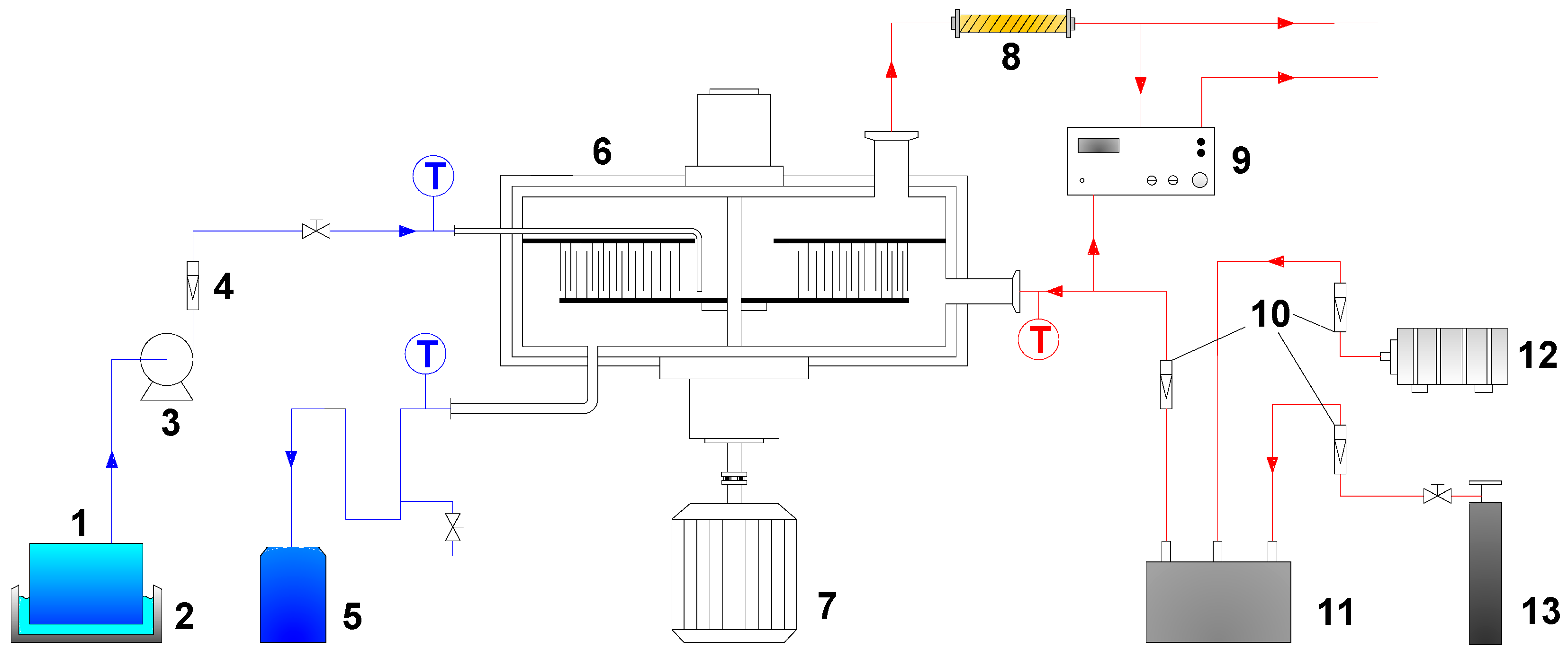
2.2. Experimental Apparatuses and Procedure

The RZB used in this work is schematically shown in Figure 1 [12], and the specifications of the RZB are given in Table 1 [12].
The rotor is the main component of the RZB. Static and rotating baffles are mounted alternately in the radial direction on the static and rotating disks, respectively, in the rotor. The upper section of the rotating baffles is perforated. The annular space between the static and rotating baffles forms the zigzag passage for fluid streams.
The shell of the RZB was covered with insulation materials to keep the reaction temperature in the RZB at a certain level, and an infrared thermometer (F-380, Shenzhen Flank Electronic Co., Ltd.) was employed to measure the temperature of the insulation materials.
The experimental setup is illustrated in Figure 2 [12]. The RZB was preheated by using a NaOH solution until a designated temperature was reached. A mixed gas stream containing air and CO2 was then directed into the RZB via the gas inlet. When CO2 concentration at the gas inlet reached 4%, the NaOH solution with a preset temperature was pumped into the RZB through the liquid inlet. The gas stream flowed inwards from the periphery of the rotor and made contact in a countercurrent with the liquid stream flowing outwards in the rotor to realize the absorption of CO2 by the NaOH solution. Finally, the liquid and gas flows left the RZB via the liquid and gas outlets, respectively.
The experiments were performed at ambient pressure, and the experimental data were collected when a stable state of CO2 absorption process was achieved. The concentration of CO2 in gas streams entering and leaving the RZB was measured by an infrared CO2 analyzer (GXH-3010F, Beijing Huayun Analytical Instrument Institution Co., Ltd., Beijing, China). All the experiments were repeated to validate the reproducibility of the results.

3. Theory

3.1. Reactions of CO2 in Sodium Hydroxide Solution

When CO2 is absorbed into the NaOH solution, the reactions between CO2 with NaOH take place. These reactions can be expressed as follows [20]:
CO 2 + NaOH NaHCO 3
NaHCO 3 + NaOH Na 2 CO 3 + H 2 O
The rate of the above reactions can be calculated by the following second-order reaction rate equation [21]:
r CO 2 = k 2 C NaOH C CO 2
The reaction can be regarded as a pseudo-first-order one when in Equation (4) is satisfied [20,22].
1 + D CO 2 k 2 C NaOH k L 2 1 C NaOH 2 C 0
where DCO2 is the diffusion coefficient of CO2 in NaOH solution.
In this study, in Equation (4) held because the left-side of in Equation (4) was over 100 times smaller than the right-side. Therefore, the rate constant of the pseudo-first-order reaction can be written as:
k app = k 2 C NaOH

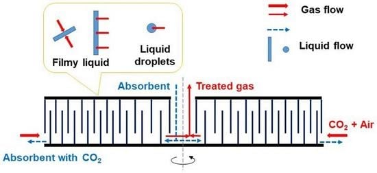
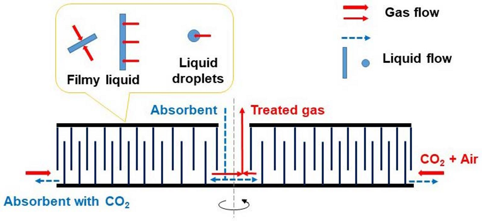
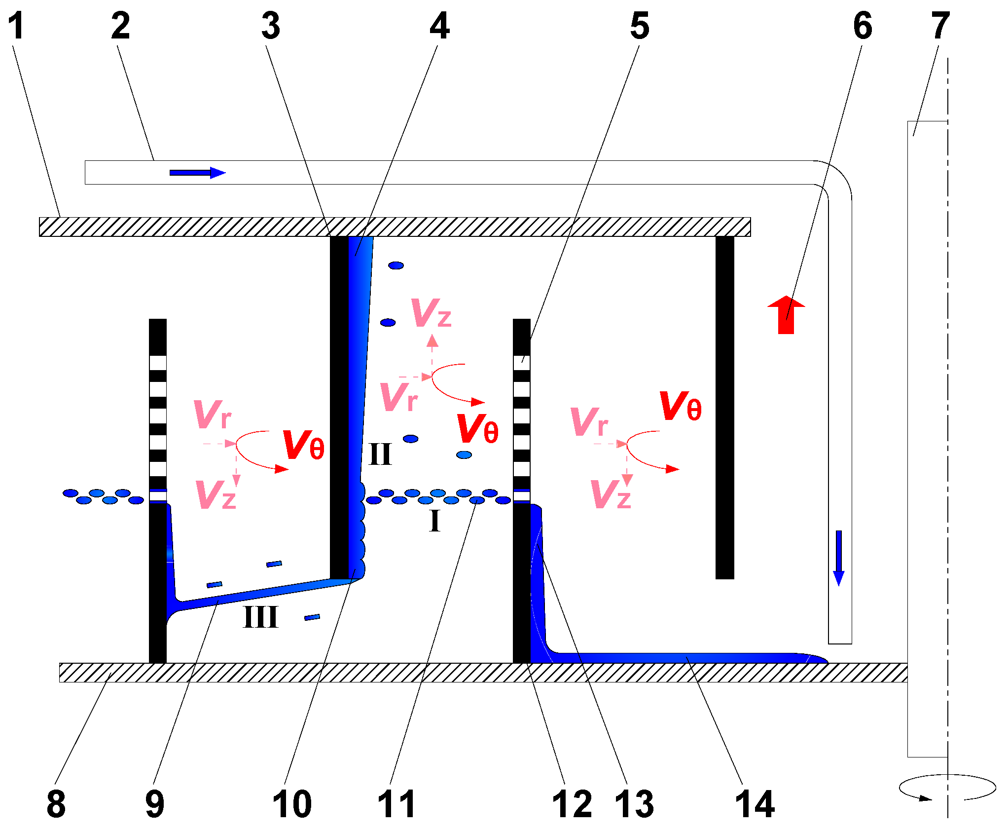
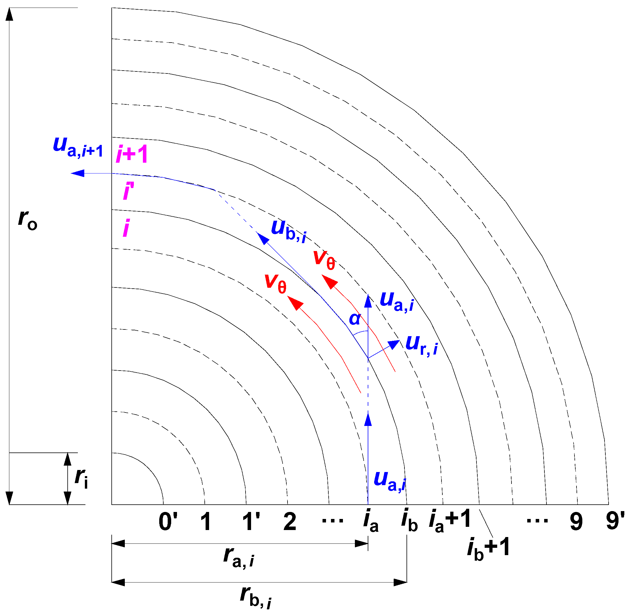
3.2. Gas and Liquid Flow in the RZB Rotor

Gas and liquid flows in the RZB rotor are presented in Figure 3. Gas flows inwards from the periphery to the center of the RZB rotor, and the gas velocity can be divided into tangential component (vθ), radial component (vr), and axial component (vz) in this process. The ratio of the tangential velocity to the total velocity is 81.6% to 99.3% [23], suggesting that gas mainly moves in a spiral between the rotating and static baffles.
The liquid flow moves outwards through the zigzag passage in the rotor. At the center of the rotating disk, liquid flows tangentially outwards under the action of centrifugal force until it reaches the internal surface of the rotating baffle and then climbs up to the perforated area. The liquid is dispersed into fine droplets when passing through the perforations in the upper section of the rotating baffle and flies along a tangential direction to the static baffle. The fine droplets are captured by the static baffle to form a filmy liquid, which flows spirally downwards on the internal surface of the static baffle due to gravity and tangential movement of the liquid. The filmy liquid departs tangentially from the static baffle as a sheet and reaches the next rotating baffle without falling onto the rotating disk because the tangential liquid velocity is much larger than the axial liquid velocity caused by gravity. The liquid is then captured by the next rotating baffle and repeats the above process in the zigzag passage until leaving the RZB rotor [10].
In terms of the above gas and liquid flow characteristics in the RZB rotor, the gas–liquid contact area can be divided into three different zones, as shown in Figure 3, as zones I, II, and III, and all of them make contributions to the mass transfer [3]. In zone I, fine droplets contact with gas in a spiral movement in the space formed by the rotating and static baffles, contributing to the gas–liquid mass transfer. In zone II, mass transfer is scarcely attributed to contact between gas and the stagnant filmy liquid formed by droplets on the upper section of the static baffle, but mainly results from the surface renewal caused by droplets continually impinging on the turbulent filmy liquid on the lower section of the static baffle [2]. In zone III, the liquid exists as an intact sheet when there is no gas flow, but some fine droplets may result from rupture of the sheet when gas flows through the passage. The contact of the flying liquid and gas in zone III also contributes to mass transfer. Hence, the rotor of the RZB can be regarded as a series of wetted-wall columns with the centrifugal field [3].
It has been reported that mass transfer in zone II contributes most to the overall mass transfer because the continued horizontal impingement by liquid jets on the turbulent filmy liquid on the static baffles brings about a great surface renewal rate. Mass transfer in zones I and III is at least one order of magnitude less than that in zone II because the renewal time of the liquid surface in zones I and III is longer than that in zone II according to the penetration theory [2].

3.3. Model Development

According to the flow characteristics of gas and liquid in the RZB rotor, model assumptions for CO2 absorption into the NaOH solution in the RZB were made as follows:
(1)
Velocity of droplets leaving the rotating baffle along the tangential direction in zone I was equal to the circumferential velocity of the rotating baffle [11].
(2)
Only the tangential velocity of gas phase in the RZB rotor was considered, and the radial and axial velocities of gas were ignored because the tangential velocity was the main component of the gas velocity [23].
(3)
It should be noted that the tangential gas velocity is smaller than the circumferential velocity of rotating baffles when the gas flow rate is low [23]. Because the gas flow rate was less than 1200 L/h in this study, the tangential gas velocity was much lower than the tangential liquid velocity in the space between the static baffle and rotating baffle. Thus, it was assumed that the effect of gas flow on the liquid form could be ignored in zone III, where the flying liquid remained in the form of an intact sheet [11]. Meanwhile, the liquid form in zones I and II was not affected by gas flow either.
(4)
Liquid existed as droplets in zone I and filmy liquid in zone II [10]. Hence, the overall gas–liquid effective interfacial area was the sum of the surface area of droplets in zone I, turbulent filmy liquid on the static baffle in zone II, and the flying intact liquid sheet in zone III [2,11].
(5)
Liquid left the rotating baffle only through the lowest circle of perforations in the rotating baffles because the perforations were closely spaced [24]. Droplets formed by every perforation had the same amount, lifetime, velocity, and diameter.
(6)
Liquid film is a thin surface layer in the filmy liquid. The liquid film in the turbulent filmy liquid in zone II was renewed by impingement of fine droplets from zone I, and the liquid film in the filmy liquid in every zone of the RZB had the same lifetime [2].
(7)
The reaction between CO2 and NaOH was considered to be a pseudo-first-order reaction. The concentration of OH in the liquid film was assumed to be constant during the CO2 absorption process, and thus kapp was regarded as a constant in the liquid element.
For the chemical absorption of CO2 into NaOH solution, CO2 is absorbed from the gas phase to the liquid phase via a gas–liquid interface. During this process, the gas–liquid mass transfer depends both on the liquid-phase and gas-phase mass transfer. Therefore, the gas–liquid effective interfacial area (a), liquid-side mass-transfer coefficient (kL), and gas-side mass-transfer coefficient (kG) should be considered for calculating KGa.
The space in the rotor of the RZB was divided into certain annular regions for model development (Figure 4). Nine rotating baffles (1, 2, …, ia, ia + 1, …, 9) and ten static baffles (0′, 1′, …, ib, ib + 1, …, 9′) were radially alternately arranged. Region i was the annular region between the rotating baffle ia of radius ra,i and static baffle ib of radius rb,i, and region i’ was the annular region between the static baffle ib of radius rb,i and rotating baffle ia + 1 of radius ra,i+1. Mass transfer zones I and II were located in region i, while zone III was in region i’.
In zone I of region i, droplets left the rotating baffle ia of radius ra,i with a tangential velocity ua,i along the tangential direction to the static baffle ib. The lifetime of droplets in zone I tI,i is written as:
t I , i = r b , i 2 r a , i 2 u a , i
u a , i = ω r a , i
where ω represents the angular velocity of the RZB rotor.
The liquid holdup of droplets εI,i in this area can be calculated by the following equation:
ε I , i = Q L t I , i π ( r b , i 2 r a , i 2 ) z = Q L π ω z r a , i r b , i 2 r a , i 2
where QL is the liquid volumetric flow rate in the RZB rotor and z is the axial depth of the rotor.
The correlation of the effective mass transfer area of droplets AI,i in zone I of region i is as follows [16]:
A I , i = a I , i π ( r b , i 2 r a , i 2 ) z = 6 ε I , i d i π ( r b , i 2 r a , i 2 ) z
where di is the average diameter of droplets in zone I of region i.
In zone II of region i, the surface area of the turbulent filmy liquid is equal to the effective mass transfer area in this zone, which can be obtained by the following equation:
A II , i = 2 π r b , i A 2 h II
where A2 is a turbulent coefficient used to correct the variation of surface area of the filmy liquid caused by the impingement of droplets (with a value of 2.19) [25] and hII represents the axial length of the turbulent filmy liquid.
In zone III of region i’, the liquid remained in the form of an intact sheet between the static and rotating baffles according to assumption (4). The filmy liquid tangentially left the static baffle of radius rb,i with a tangential velocity of ub,i, and thus the lifetime of the flying filmy liquid in zone III of region itIII,i is expressed as follows:
t III , i = r a , i + 1 2 r b , i 2 u b , i = r a , i + 1 2 r b , i 2 u a , i r a , i r b , i
Thus, the surface area of the flying filmy liquid equals the gas–liquid effective mass transfer area in this zone:
A III , i = ( 2 π r b , i + 2 π r a , i + 1 ) ( r a , i + 1 r b , i ) 2 + ( u g , i t III , i + 1 2 g t III , i 2 ) 2
where ug,i is the axial component of the turbulent filmy liquid velocity in zone II.
Therefore, the gas–liquid effective interfacial area in the RZB rotor can be obtained as follows:
a = a I + a II + a III = i = 1 9 A I , i + i = 1 9 A II , i + i = 1 8 A III , i π ( r o 2 r i 2 ) z
The mass transfer in the liquid phase consists of that in the droplets and filmy liquid. Because the droplets were treated as rigid balls without inside circulation during the flight due to a small distance in zone I of region i [26], the following mass partial differential equation can be used to present the CO2 diffusion process from gas bulk to droplets based on the pseudo-first-order irreversible chemical reaction:
C CO 2 t I , i = D CO 2 2 C CO 2 R 2 + 2 D CO 2 R C CO 2 R k app ( C CO 2 C CO 2 * )
I . C .   t I , i = 0 ,   R 0 :   C CO 2 = C CO 2 * ;
B . C .   R = 0 ,   t I , i 0 :   C CO 2 = C CO 2 * ;
R = d i 2 ,   t I , i 0 :   C CO 2 = C 0 ;
where C0 (=PCO2,0/H) and CCO2* are the molar concentration of CO2 at the gas–liquid interface and the equilibrium molar concentration of CO2 in the liquid bulk, respectively.
Letting CA = CCO2CCO2*, the following expressions can be obtained:
C A t I , i = D CO 2 2 C A R 2 + 2 D CO 2 R C A R k app C A
I . C .   t I , i = 0 ,   R 0 :   C A = 0 ;
B . C .   R = 0 ,   t I , i 0 :   C A = 0 ;
R = d i 2 ,   t I , i 0 :   C A = C 0 C CO 2 * ;
After Laplace transform, the following ordinary differential equation is derived:
d 2 u d R 2 + 2 R d u d R k app + s D CO 2 u = 0
Letting β = u × R, Equation (22) can be obtained by Equations (19)–(21).
d β d R = d u d R R + u
d 2 β d R 2 = d 2 u d R 2 R + 2 d u d R
1 R d 2 β d R 2 = d 2 u d R 2 + 2 R d u d R
d 2 β d R 2 = k a p p + s D C O 2 β
The general solution of β can be calculated by Equation (23):
β = u × R = C 1 e R k app + s D CO 2 + C 2 e R k app + s D CO 2
Then, the following equation is obtained by Laplace inverse transform:
C A = C 1 2 R e x p ( R k app D CO 2 ) e r f c ( R 2 D CO 2 t I , i k app t I , i )     + C 1 2 R e x p ( R k app D CO 2 ) e r f c ( R 2 D CO 2 t I , i + k app t I , i )     + C 2 2 R e x p ( R k app D CO 2 ) e r f c ( R 2 D CO 2 t I , i k app t I , i )     + C 2 2 R e x p ( R k app D CO 2 ) e r f c ( R 2 D CO 2 t I , i + k app t I , i )
where erfc(x) is the excess error function.
To simplify Equation (24), B is defined as follows:
B = e x p ( d i 2 k app D CO 2 ) e r f ( d i 2 2 D CO 2 t I , i + k app t I , i ) + e x p ( d i 2 k app D CO 2 ) e r f ( d i 2 2 D CO 2 t I , i k app t I , i )
where erf(x) is the error function.
Letting C1 = −C2 and substituting Equation (17) into Equation (24), C1 and C2 can be expressed as follows:
C 1 = C 0 C CO 2 * 2 B d i
C 2 = C 1 = C 0 C CO 2 * 2 B d i
Therefore, Equation (28) can be obtained by combining Equations (24), (26) and (27):
C A = ( C 0 C CO 2 * ) d i 2 R B e x p ( R k app D CO 2 ) e r f ( R 2 D CO 2 t I , i + k app t I , i ) + ( C 0 C CO 2 * ) d i 2 R B   e x p ( R k app D CO 2 ) e r f ( R 2 D CO 2 t I , i k app t I , i )
In terms of Fick’s first law, the rate equation describing mass transfer at the gas–liquid interface can be written as:
k L I , i ( C CO 2 C CO 2 * ) = D CO 2 C A R R = d i 2
It was assumed that CO2 was completely consumed by chemical reaction of CO2 and NaOH in the liquid bulk. Thus, CCO2* can be ignored, and kL−I,i in zone I is given by Equation (30):
k L I , i = k app D CO 2 2 D CO 2 d i
In regard to liquid film in the turbulent filmy liquid in zone II of region i, CO2 diffusion into the liquid film with a pseudo-first-order reaction can be expressed as:
C CO 2 t II , i = D CO 2 2 C CO 2 x 2 k app ( C CO 2 C CO 2 * )
I . C .   t II , i = 0 ,   x 0 :   C CO 2 = C CO 2 * ;
B . C .   x = 0 , t II , i 0 :   C CO 2 = C 0 ;
x = δ ( ) , t II , i 0 :   C CO 2 = C CO 2 * ;
where δ is the average thickness of the liquid film in zone II and tII,i is the lifetime of the liquid film, which is the average time consumed for renewing the liquid film once.
The following equation can be obtained from Equations (31) and (32):
C A t II , i = D CO 2 2 C A x 2 k app C A
I . C .   t II , i = 0 ,   x 0 :   C A = 0 ;
B . C .   x = 0 , t II , i 0 :   C A = C 0 C CO 2 * ;
x = δ ( ) , t II , i 0 :   C A = 0 ;
By Laplace transform, the following equation is derived:
d 2 u d x 2 k app + s D CO 2 u = 0
B . C .   x = 0 ,   s 0 :   u = C 0 C CO 2 * s ;
x = δ ( ) ,   s 0 :   u = 0 ;
Substituting the boundary conditions in Equation (36) into Equation (35), the general solution of u can be obtained by Equation (37):
u = C 0 C CO 2 * s e x p ( x k app + s D CO 2 )
By the Laplace inverse transform, the relationship of the CO2 concentration distribution, lifetime, and liquid film thickness can be described by the following equation:
C A = ( C 0 C CO 2 * ) 2 e x p ( x k app D CO 2 ) e r f c ( x 2 D CO 2 t II , i + k app t II , i ) + ( C 0 C CO 2 * ) 2 e x p ( x k app D CO 2 ) e r f c ( x 2 D CO 2 t II , i k app t II , i )
Hence, the mass transfer rate at the gas–liquid interface in zone II can be obtained based on Fick’s first law.
R CO 2 II , i = D CO 2 C A x x = 0 = ( C 0 C CO 2 * ) ( k app D CO 2   e r f k app t II , i + D CO 2 π t II , i e x p ( k app t II , i ) )
According to assumptions (5) and (6), the renewal of the liquid film in zone II was caused by the impingement of droplets, which came from the lowest circle of the perforated area in the rotating baffle. It was assumed that the droplets formed by every perforation had the same amount, lifetime, velocity, and diameter. Therefore, the renewal frequency, Si, defined as the number of droplets leaving the rotating baffles per unit time, in zone II of region i is expressed as:
S i = 36 Q L π n a , i d i 3
where na,i is the number of perforations in the rotating baffle ia.
Then the lifetime of the liquid film in the turbulent filmy liquid can be calculated by Equation (41) [18]:
t II , i = 1 S i
It was assumed that tII,i caused by every droplet was the same. Thus, Equation (42) can be used to express the Higbie distribution function of the lifetime of the liquid film [16]:
ψ ( t II , i ) = 1 t II , i
Hence, the relationship between the liquid-side mass-transfer coefficient in zone II (kL−II,i) and the mass transfer rate of liquid film at the gas–liquid interface can be written as:
0 t II , i R CO 2 II , i ψ ( t II , i ) d t = k L II . i ( C 0 C CO 2 * )
Based on the same assumption for droplets, CCO2* can be ignored. Therefore, kL−II,i related to kapp, DCO2, and tII,i can be deduced as follows:
k L II . i = k app D CO 2 t II , i [ t II , i e r f ( k app t II , i ) + t II , i π k app e x p ( k app t II , i ) + 1 2 k app e r f ( k app t II , i ) ]
As for the liquid film in the flying filmy liquid in zone III of region i’, the model development process of kL−III,i was the same as that of kL−II,I, and thus the expression of kL−III,i was similar to that of kL−II,i, except for the lifetime of the liquid film in the flying filmy liquid, which was calculated by Equation (11).
Hence, kLa in the RZB rotor is written as follows:
k L a = k L I a I + k L II a II + k L III a III = i = 1 9 k L I , i A I , i + i = 1 9 k L II , i A II , i + i = 1 8 k L III , i A III , i π ( r o 2 r i 2 ) z
To date, there is no available expression to calculate kG in the RZB rotor. Thus, a surface renewal model reported by Guo et al. [27] was employed to calculate kG in the RZB rotor as follows:
k G = D G k s v θ 2
where DG is the diffusion coefficient of CO2 in gas phase, ks is the proportionality coefficient, and vθ is the average tangential gas velocity in the RZB rotor.
The KGa of the RZB can be calculated by [15]:
1 K G a = 1 k G a + H k L a
The experimental KGa can be determined by Equation (48), which was obtained in the previous study on CO2 absorption [12]:
K G a = G π P z ( r o 2 r i 2 ) [ ln y CO 2 in ( 1 y CO 2 out ) y CO 2 out ( 1 y CO 2 in ) + ( y CO 2 in 1 y CO 2 in y CO 2 out 1 y CO 2 out ) ]
where G’ is the inlet gas flow rate of inert gas (without reaction or dissolution), P is the total pressure, and y CO 2 in and y CO 2 out denote the molar fraction of CO2 in the inlet and outlet gas streams, respectively.
By substituting the experimental KGa from Equation (48) and the calculated kLa and a from Equations (45) and (13), respectively, into Equation (47), kG can be obtained. Consequently, ks can be obtained, which is necessary for the establishment of the mass transfer model. Thus, the calculated kG, kL, a, and KGa for the RZB were obtained from this mass transfer model.
The density and viscosity values were obtained from reference [28], while the surface tension value was from reference [29]. The equilibrium, kinetics, and transport parameters used for modeling are tabulated in Table 2.

4. Results and Discussion

4.1. Model Validation

The RZB had an average value for ks of 6.17 × 10⁻⁸ kmol2 s/kPa2 m8 under the experimental conditions. By using kL, kG, and a obtained from the above model and the average value of ks, the calculated KGa of the RZB was obtained according to Equation (47). The comparison of kL, kG, and a between this work and reference [10] can be found in Table S1 in the Supplementary Materials file.
Figure 5 is the diagonal diagram of the predicted and experimental values of KGa. It is shown that this model provided good predictions on KGa of CO2 absorption in the RZB, with deviations generally less than 10% in comparison with the experimental results. Additionally, in the Figures shown in Section 4.2, Section 4.3, Section 4.4, Section 4.5 and Section 4.6, the curves for the predicted values were consistent with those for the experimental results. In addition, the values of individual and overall mass transfer parameters have been presented in Table S2 in the Supplementary Materials file.

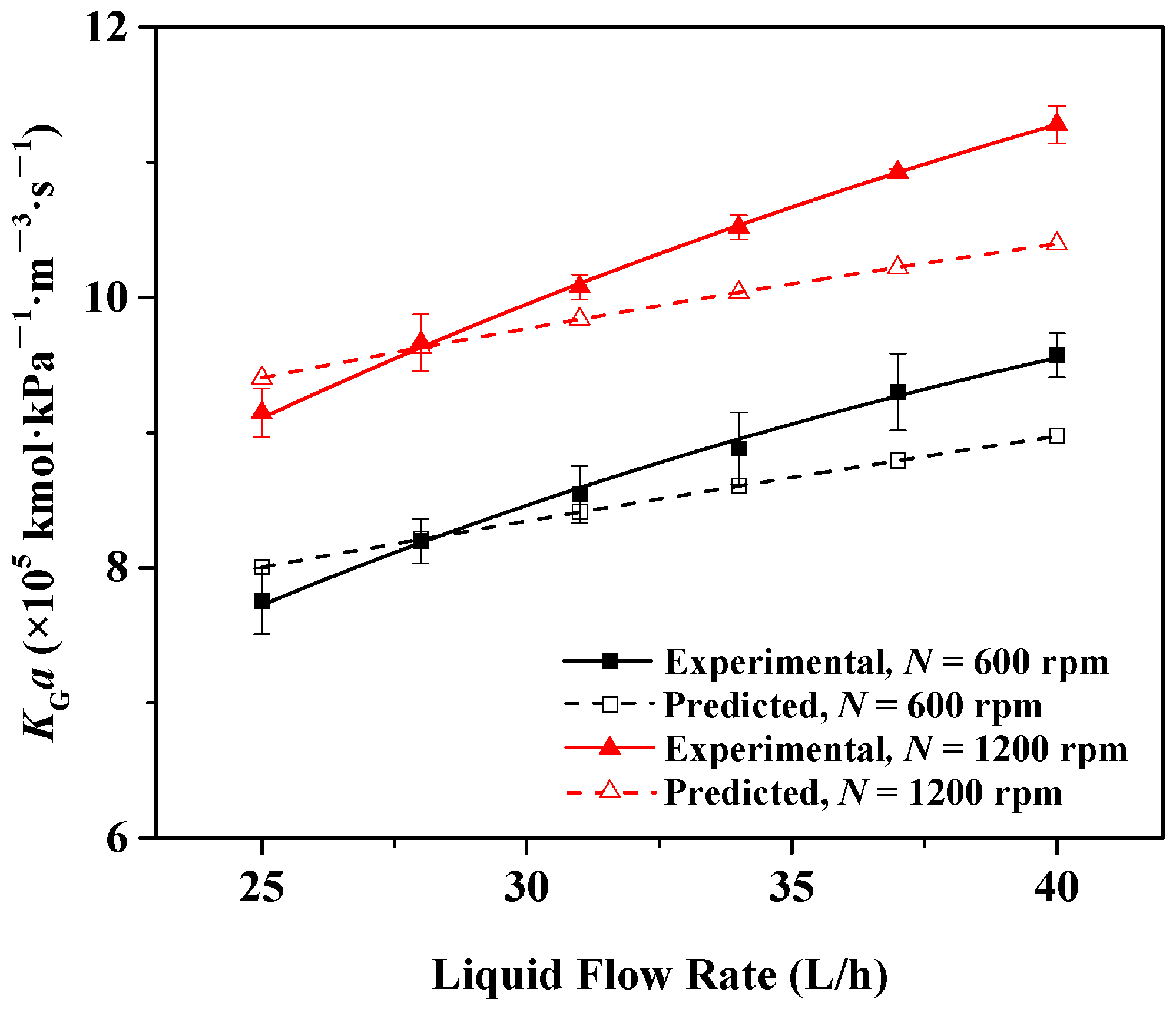
4.2. Effect of Liquid Flow Rate

Figure 6 presents the effect of the liquid flow rate on KGa in the RZB. It can be seen that KGa in NaOH solution obviously increased, with a rise in the liquid flow rate from 25 to 40 L/h.
With a rising liquid flow rate, more fine droplets from the rotating baffles are produced. The falling velocity of the filmy liquid on the static baffles also increases in terms of the expression of ug,i in Table 2, causing an increasing area of the flying liquid sheet between the static and rotating baffles according to Equation (12). These factors enhance the liquid holdup in the RZB, thereby causing a rising gas–liquid contact area based on Equation (8). Meanwhile, with the increase of the liquid flow rate, the circumferential distribution of droplets in zone I is improved [10], and more droplets continually impinge on the filmy liquid on the lower section of the static baffles, leading to an enhancement of liquid turbulence and a higher surface renewal rate of liquid film in the turbulent filmy liquid in zone II, as suggested by Equation (40), which are conducive to the liquid-side mass transfer. Therefore, a higher liquid flow rate brought about a larger KGa in this study because a and kL contributed notably to KGa for CO2 absorption into NaOH solution.

4.3. Effect of Inlet Gas Flow Rate

The influence of the inlet gas flow rate on KGa in the RZB is given in Figure 7, which shows that KGa in the NaOH solution rose from 6.13 × 10⁻⁵ to 8.26 × 10⁻⁵ kmol/kPa m3 s and from 6.67 × 10⁻⁵ to 9.65 × 10⁻⁵ kmol/kPa m3 s, with the inlet gas flow rate increasing from 200 to 1200 L/h at the rotational speed of 600 rpm and 1200 rpm, respectively.
Because KGa in the NaOH solution is affected by kGa, a rising inlet gas flow rate in the RZB increases the tangential gas velocity in the annular space between the rotating and static baffles, which leads to the increase of gas turbulence and a decrease of gas film thickness [16]. Therefore, the mass transfer resistance in the gas side reduces and consequently kGa increases, thereby enhancing KGa in the RZB. Hence, an increasing inlet gas flow rate brought about a rise in KGa in the experimental range.

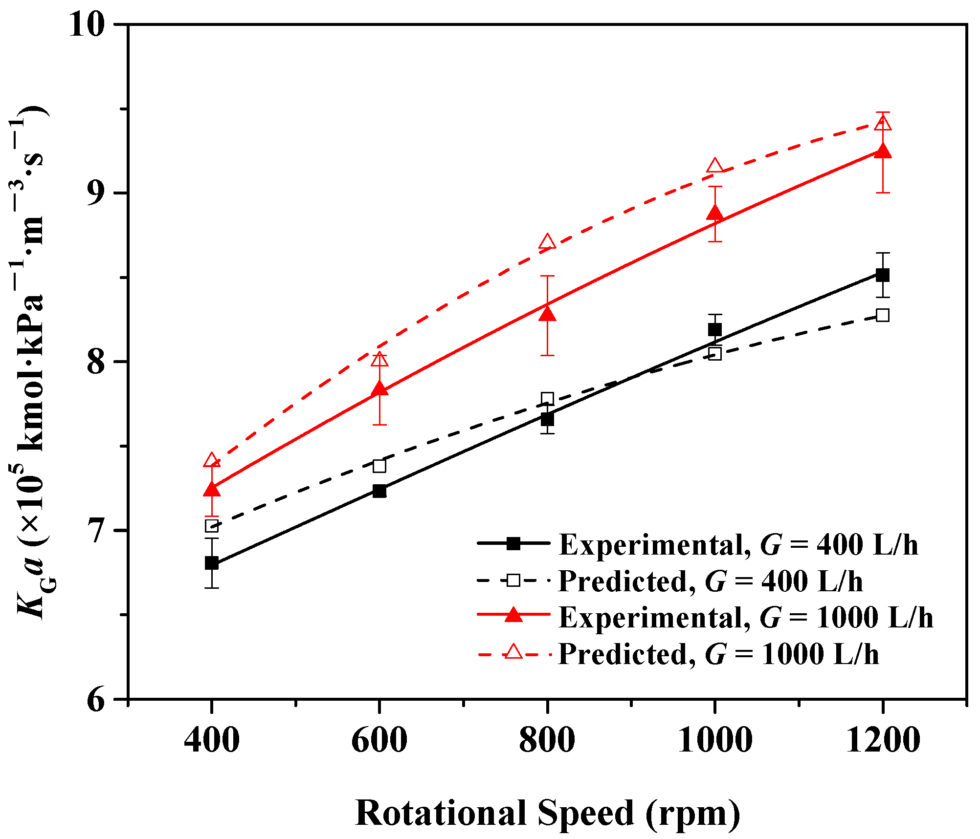
4.4. Effect of Rotational Speed

The variation of KGa with the rotational speed is shown in Figure 8. KGa augmented with a rise in the rotational speed from 400 to 1200 rpm.
When the rotational speed rises, a larger centrifugal force is created by the rotating baffles, leading to an enhanced liquid turbulence and higher tangential velocity of droplets departing from the rotating baffles according to Equation (7), which reduces the size of droplets in the space between the rotating and static baffles based on the expression of droplet diameter in Table 2. Therefore, a in zone I increase.
At the same time, rising rotational speed causes an increase in the number of droplets impinging on the turbulent filmy liquid as a result of the reduction in droplet size and a larger circumferential velocity of the turbulent filmy liquid in zone II, which is equal to the tangential velocity of the flying liquid sheet leaving the static baffles in zone III [11], resulting in a rise in the surface renewal frequency of the liquid film in the turbulent filmy liquid on the static baffles in terms of Equation (40) and a decrease in the lifetime of the flying liquid sheet in zone III according to Equation (11). The former factor brought about an increase in kL−II in zone II, and the latter factor was conducive to kL-III in zone III according to Equation (44).
The above analysis indicates that a higher rotational speed led to higher a and kL, which markedly an enhanced KGa of the CO2-NaOH system in the RZB.

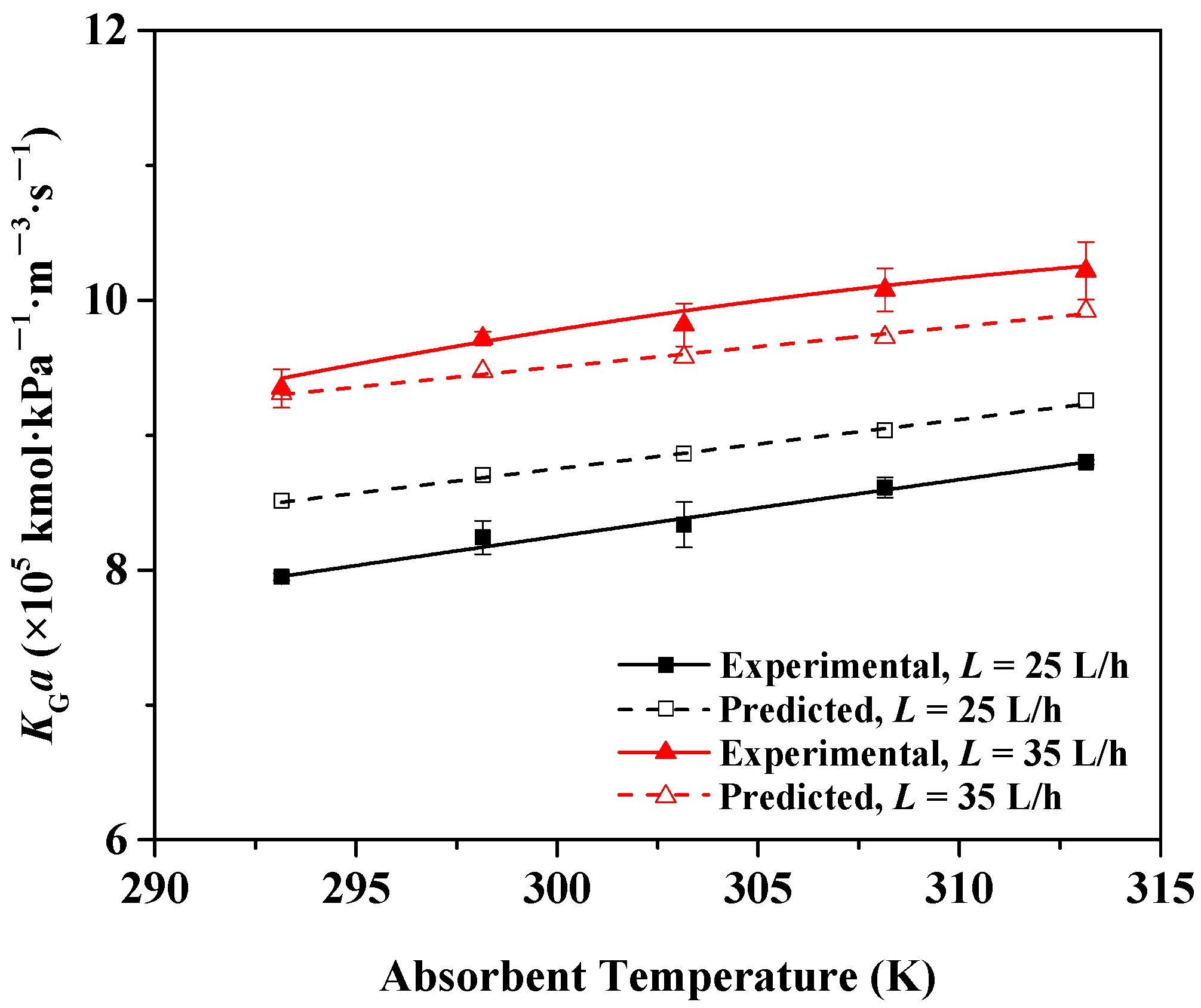
4.5. Effect of Absorbent Temperature

The effect of the absorbent temperature on KGa is presented in Figure 9. The figure indicates that a higher temperature of NaOH solution is favorable for KGa, which increased from 7.95 × 10⁻⁵ to 8.80 × 10⁻⁵ kmol/kPa m3 s and from 9.35 × 10⁻⁵ to 1.02 × 10⁻⁴ kmol/kPa m3 s with an increase in temperature from 293.15 to 313.15 K at the liquid flow rate of 25 L/h and 35 L/h, respectively.
In accordance with the Arrhenius equation for the reaction rate constant in Table 2, a higher temperature of NaOH solution increases the second-order rate constant k2, thereby leading to a larger pseudo-first-order reaction rate constant kapp, which is favorable for the liquid-side mass transfer performance. Moreover, the resistance in liquid-side mass transfer reduces and the diffusion of CO2 in the liquid phase is improved with increasing temperature [12]. These factors promoted mass transfer and caused a higher kL, thereby leading to an increasing KGa.

4.6. Effect of Absorbent Concentration

Figure 10 illustrates the effect of NaOH absorbent concentration on KGa in the RZB. It is noted that KGa increased from 7.43 × 10⁻⁵ to 9.25 × 10⁻⁵ kmol/kPa m3 s with an increase in the absorbent concentration from 0.1 to 0.2 mol/L at the liquid flow rate of 25 L/h, while KGa increased from 8.62 × 10⁻⁵ to 1.07 × 10⁻⁴ kmol/kPa m3 s as the absorbent concentration rose from 0.1 to 0.2 kmol/m3 at the liquid flow rate of 35 L/h.
When the concentration of NaOH solution increases, the second-order reaction rate constant between CO2 and the absorbent rises according to the expression of k2 shown in Table 2. Meanwhile, a higher k2 and CNaOH can concurrently enhance the pseudo-first-order reaction rate constant kapp, causing a higher kL in every mass transfer zone of the RZB. Hence, KGa increased with an increasing NaOH concentration.

4.7. Comparison between Spray Column and RZB

Table 3 reveals comparative results of mass transfer efficiency between a spray column and the RZB. It was found that the experimental KGa in the spray column was less than that in the RZB on the basis of a similar gas–liquid volume ratio. Additionally, the RZB possessed a greater mass transfer efficiency accompanied by a much lower NaOH solution concentration compared to the spray column, suggesting that an obvious enhancement of mass transfer in CO2 absorption can be realized by the RZB.
Considering an enhanced dispersion and coalescence of the liquid phase in the annular regions between the static and rotating baffles, a shorter lifetime of the liquid element in the RZB is gained compared to the spray column, and the intensification of mass transfer is thus expected in the RZB, conducing to the CO2 absorption process.

5. Conclusions

In this study, by obtaining the analytical expressions of the gas–liquid effective interfacial area, liquid-side and gas-side mass-transfer coefficients in an RZB, a mathematic model of CO2 absorption into NaOH solution with irreversible pseudo-first-order reaction in the RZB was established to quantitatively describe the gas–liquid mass transfer process and predict KGa.
The KGa calculated by the model was consistent with the experimental data under different operating conditions. The calculated KGa exhibited deviations generally less than 10% in comparison with the experimental data, which demonstrated the excellent predictability of this model for CO2 absorption in an RZB. Meanwhile, the influences of various operating conditions on KGa in the RZB were predicted reasonably by this model. Experimental results indicate that higher liquid flow rate, inlet gas flow rate, rotational speed, absorbent temperature, and absorbent concentration favored gas–liquid mass transfer in the RZB. It was found that the rotational speed had the largest impact on KGa in the RZB. This study provides the theoretical basis for potential application of RZBs in CO2 absorption.

Supplementary Materials

The following supporting information can be downloaded at: https://www.mdpi.com/article/10.3390/pr10030614/s1, Table S1: Comparison of mass transfer performance between RZB in this work and that in Reference 10; Table S2: Values of individual and overall mass transfer factors in RZB.

Author Contributions

Conceptualization, L.S.; methodology, Z.L.; validation, A.E.; formal analysis, H.Z.; investigation, D.W.; resources, Y.L.; data curation, Z.L.; writing—original draft preparation, Z.L.; writing—review and editing, Z.L.; supervision, L.S.; project administration, L.S.; funding acquisition, L.S. All authors have read and agreed to the published version of the manuscript.

Funding

This research was funded by the National Natural Science Foundation of China, grant number 22178021.

Institutional Review Board Statement

Not applicable.

Informed Consent Statement

Not applicable.

Data Availability Statement

Not applicable.

Acknowledgments

The authors gratefully acknowledge financial support from the National Natural Science Foundation of China (No. 22178021).

Conflicts of Interest

The authors declare no conflict of interest.

Nomenclature

agas–liquid effective interfacial area, m2/m3
aI, aII, aIIIgas–liquid effective interfacial area in zone I, II, and III, respectively, m2/m3
aI,igas–liquid effective interfacial area in zone I of region i, m2/m3
AI,i, AII,ieffective mass transfer area in zone I and II of region i, respectively, m2
AIII,ieffective mass transfer area in zone III of region i’, m2
A2turbulent coefficient
CAdifference between actual and equilibrium CO2 concentration in liquid phase,
kmol/m3, CA = CCO2CCO2*
CCO2concentration of CO2 in liquid phase, kmol/m3
CCO2*equilibrium concentration of CO2 in liquid bulk, kmol/m3
C0concentration of CO2 at gas–liquid interface, kmol/m3
CNaOHconcentration of NaOH solution, kmol/m3
diaverage droplet diameter in zone I of region i, m
DCO2diffusion coefficient of CO2 in NaOH solution, m2/s
DGdiffusion coefficient of CO2 in gas phase, m2/s
DWdiffusion coefficient of CO2 in water, m2/s
gacceleration of gravity, m/s2
Ginlet gas flow rate, L/h
Ginlet flow rate of inert gas (without reaction and dissolution), kmol/s
hconstant related to h+, h, hg, m3/kmol
h+, h, hgconstant of cation, anion, and gas, respectively, m3/kmol
hIIaxial length of turbulent filmy liquid, m
HHenry’s constant of NaOH solution, kPa m3/kmol
HWHenry’s constant of water, kPa m3/kmol
Iionic strength, kmol/m3
k2second-order reaction rate constant, m3/kmol s
kapppseudo-first-order rate constant, 1/s
kGgas-side mass-transfer coefficient, kmol/kPa m2 s
KGaoverall gas-phase volumetric mass-transfer coefficient, kmol/kPa m3 s
kLliquid-side mass-transfer coefficient, m/s
kL−I, kL−II, kL−IIIliquid-side mass-transfer coefficient in zone I, II, and III, respectively, m/s
kL−I,i, kL−II,iliquid-side mass-transfer coefficient in zone I and II of region i, respectively, m/s
kL−III,iliquid-side mass-transfer coefficient in zone III of region i’, m/s
kLaliquid-side volumetric mass-transfer coefficient, 1/s
k OH reaction rate constant in infinitely dilute NaOH solution, m3/kmol s
ksproportionality coefficient, kmol2 s/kPa2 m8
Lliquid flow rate, L/h
na,inumber of perforations in rotating baffle ia
Pgas phase pressure, kPa
PCO2,0partial pressure of CO2 in gas phase at gas–liquid interface, kPa
QGgas volumetric flow rate, m3/s
QLliquid volumetric flow rate, m3/s
ra,iradius of rotating baffle ia, m
rb,iradius of static baffle ib, m
rhhydraulic radius of annular region between rotating and static baffles, m
riinner radius of rotor, m
roouter radius of rotor, m
rmradius of logarithmic mean, m
rCO2reaction rate of CO2 with NaOH solution, kmol/m3 s
Rradial coordinate of a droplet, m
RCO2-II,imass transfer rate of liquid film at the gas–liquid interface in zone II of region
i, mol/m2 s
ReG gas Reynolds number, R e G = 4 r h v G ρ G μ G
scomplex variable
Sirenewal frequency of liquid film in zone II of region i, 1/s
tI,ilifetime of droplets in zone I of region i, s
tII,ilifetime of liquid film in turbulent filmy liquid in zone II of region i, s
tIII,ilifetime of liquid film in flying filmy liquid in zone III of region i’, s
Tabsorbent temperature, K
Tgasgas temperature at gas inlet of RZB, K
ua,itangential velocity of droplets leaving rotating baffle ia, m/s
ub,itangential velocity of flying filmy liquid leaving static baffle ib, m/s
ur,iradial component of ua,i, m/s
ug,iaxial component of turbulent filmy liquid velocity on static baffle ib, m/s
vGgas velocity in annular region between rotating and static baffles, m/s
vθaverage tangential component of gas velocity, m/s
vrradial component of gas velocity, m/s
vzaxial component of gas velocity, m/s
vingas velocity at gas inlet of RZB, m/s
xliquid film thickness of filmy liquid from gas–liquid interface, m
yCO2-inmolar fraction of CO2 in gas inlet of RZB, %
yCO2-outmolar fraction of CO2 in gas outlet of RZB, %
zaxial depth of rotor, m
αangle between ua,i and tangent to static baffle ib, °
ωangular velocity, rad/s
εI,iliquid holdup of droplets in zone Iof, region i
δaverage thickness of liquid film in zone II, m
ρGdensity of gas phase, kg/m3
ρLdensity of NaOH solution, kg/m3
μGviscosity of gas phase, pa s
μLviscosity of NaOH solution, pa s
μWviscosity of water, pa s
σsurface tension of NaOH solution, N/m

References

  1. Li, Y.; Liu, P.; Wang, G.; Ji, J. Enhanced mass transfer and reduced pressure drop in a compound rotating zigzag bed. Sep. Purif. Technol. 2020, 250, 117188. [Google Scholar] [CrossRef]
  2. Wang, G.; Zhou, Z.; Li, Y.; Ji, J. Qualitative relationships between structure and performance of rotating zigzag bed in distillation. Chem. Eng. Process.-Process Intensif. 2019, 135, 141–147. [Google Scholar] [CrossRef]
  3. Wang, G.; Xu, Z.; Ji, J. Progress on higee distillation—Introduction to a new device and its industrial applications. Chem. Eng. Res. Des. 2011, 89, 1434–1442. [Google Scholar] [CrossRef]
  4. Wang, G.; Xu, Z.; Yu, Y.; Ji, J. Performance of a rotating zigzag bed—A new Higee. Chem. Eng. Process.-Process Intensif. 2008, 47, 2131–2139. [Google Scholar] [CrossRef]
  5. Wang, G.; Xu, O.; Xu, Z.; Ji, J. New Higee-rotating zigzag bed and its mass transfer performance. Ind. Eng. Chem. Res. 2008, 47, 8840–8846. [Google Scholar] [CrossRef]
  6. Li, Y.; Li, X.; Wang, Y.; Chen, Y.; Ji, J.; Yu, Y.; Xu, Z. Distillation in a counterflow concentric-ring rotating bed. Ind. Eng. Chem. Res. 2014, 53, 4821–4837. [Google Scholar] [CrossRef]
  7. Wang, Z.; Yang, T.; Liu, Z.; Wang, S.; Gao, Y.; Wu, M. Mass transfer in a rotating packed bed: A critical review. Chem. Eng. Process.-Process Intensif. 2019, 139, 78–94. [Google Scholar] [CrossRef]
  8. Karmakar, S.; Bhowal, A.; Das, P. A comparative study of liquid-liquid extraction in different rotating bed contactors. Chem. Eng. Process.-Process Intensif. 2018, 132, 187–193. [Google Scholar] [CrossRef]
  9. Liang, Z.; Wei, T.; Xie, J.; Li, H.; Liu, H. Direct conversion of terminal alkenes to aldehydes via ozonolysis reaction in rotating zigzag bed. J. Iran. Chem. Soc. 2020, 17, 2379–2384. [Google Scholar] [CrossRef]
  10. Li, Y.; Lu, Y.; Liu, X.; Wang, G.; Nie, Y.; Ji, J. Mass-transfer characteristics in a rotating zigzag bed as a Higee device. Sep. Purif. Technol. 2017, 186, 156–165. [Google Scholar] [CrossRef]
  11. Li, Y.; Yu, Y.; Xu, Z.; Li, X.; Liu, X.; Ji, J. Rotating zigzag bed as trayed Higee and its power consumption. Asia-Pac. J. Chem. Eng. 2013, 8, 494–506. [Google Scholar] [CrossRef]
  12. Liu, Z.; Esmaeili, A.; Zhang, H.; Xiao, H.; Yun, J.; Shao, L. Carbon dioxide absorption with aqueous amine solutions promoted by piperazine and 1-methylpiperazine in a rotating zigzag bed. Fuel 2021, 302, 121165. [Google Scholar] [CrossRef]
  13. Zhang, L.; Wang, J.; Xiang, Y.; Zeng, X.; Chen, J. Absorption of carbon dioxide with ionic liquid in a rotating packed bed contactor: Mass transfer study. Ind. Eng. Chem. Res. 2011, 50, 6957–6964. [Google Scholar] [CrossRef]
  14. Yi, F.; Zou, H.; Chu, G.; Shao, L.; Chen, J. Modeling and experimental studies on absorption of CO2 by benfield solution in rotating packed bed. Chem. Eng. J. 2009, 145, 377–384. [Google Scholar] [CrossRef]
  15. Sun, B.; Wang, X.; Chen, J.; Chu, G.; Chen, J.; Shao, L. Simultaneous absorption of CO2 and NH3 into water in a rotating packed bed. Ind. Eng. Chem. Res. 2009, 48, 11175–11180. [Google Scholar] [CrossRef]
  16. Wang, D.; Liu, T.; Ma, L.; Wang, F.; Shao, L. Modeling and experimental studies on ozone absorption into phenolic solution in a rotating packed bed. Ind. Eng. Chem. Res. 2019, 58, 7052–7062. [Google Scholar] [CrossRef]
  17. Zhao, Z.; Zhang, X.; Li, G.; Chu, G.; Sun, B.; Zou, H.; Arowo, M.; Shao, L. Mass transfer characteristics in a rotor-stator reactor. Chem. Eng. Technol. 2017, 40, 1078–1083. [Google Scholar] [CrossRef]
  18. Qian, Z.; Xu, L.; Cao, H.; Guo, K. Modeling study on absorption of CO2 by aqueous solutions of n-methyldiethanolamine in rotating packed bed. Ind. Eng. Chem. Res. 2009, 48, 9261–9267. [Google Scholar] [CrossRef]
  19. Zhang, L.; Wang, J.; Liu, Z.; Lu, Y.; Chu, G.; Wang, W.; Chen, J. Efficient capture of carbon dioxide with novel mass-transfer intensification device using ionic liquids. AlChE J. 2013, 59, 2957–2965. [Google Scholar] [CrossRef]
  20. Luo, Y.; Chu, G.; Zou, H.; Wang, F.; Xiang, Y.; Shao, L.; Chen, J. Mass transfer studies in a rotating packed bed with novel rotors: Chemisorption of CO2. Ind. Eng. Chem. Res. 2012, 51, 9164–9172. [Google Scholar] [CrossRef]
  21. Tsai, C.; Chen, Y. Effective interfacial area and liquid-side mass transfer coefficients in a rotating bed equipped with baffles. Sep. Purif. Technol. 2015, 144, 139–145. [Google Scholar] [CrossRef]
  22. Li, Y.; Si, J.; Arowo, M.; Liu, Z.; Sun, B.; Song, Y.; Chu, G.; Shao, L. Experimental investigation of effective gas-liquid specific interfacial area in a rotor-stator reactor. Chem. Eng. Process.-Process Intensif. 2020, 148, 107801. [Google Scholar] [CrossRef]
  23. Wang, H.; Li, Y.; Ji, J. Experimental study on gas flow field in a rotating zigzag bed. Chin. J. Process Eng. 2010, 10, 56–59. (In Chinese) [Google Scholar]
  24. Li, Y.; Lu, Y.; Wang, G.; Nie, Y.; Ying, H.; Ji, J.; Liu, X. Liquid entrainment and flooding in a rotating zigzag bed. Ind. Eng. Chem. Res. 2015, 54, 2554–2563. [Google Scholar] [CrossRef]
  25. Lu, Y.; Li, Y.; Yu, Y.; Liu, X.; Ji, J. Study on liquid hold-up of rotating zigzag bed. Chin. J. Process Eng. 2014, 14, 568–572. (In Chinese) [Google Scholar]
  26. Cao, Z. Investigation into the Absorption in a Cyclone Absorber of Spraying Liquid from Side Wall. Ph.D. Thesis, South Yangtze University, Wuxi, China, 2008. (In Chinese). [Google Scholar]
  27. Guo, F.; Zheng, C.; Guo, K.; Feng, Y.; Gardner, N. Hydrodynamics and mass transfer in cross-flow rotating packed bed. Chem. Eng. Sci. 1997, 52, 3853–3859. [Google Scholar] [CrossRef]
  28. Liu, G.; Ma, L.; Xing, Z. Handbook of Chemical Property Chart; Chemical Industry Press: Beijing, China, 2002; pp. 47–163. (In Chinese) [Google Scholar]
  29. Dutcher, C.; Wexler, A.; Clegg, S.L. Surface tensions of inorganic multicomponent aqueous electrolyte solutions and melts. J. Phys. Chem. A 2010, 114, 12216–12230. [Google Scholar] [CrossRef] [PubMed]
  30. Sheng, M.; Xie, C.; Sun, B.; Luo, Y.; Zhang, L.; Chu, G.; Zou, H.; Chen, J. Effective mass transfer area measurement using a CO2–NaOH system: Impact of different sources of kinetics models and physical properties. Ind. Eng. Chem. Res. 2019, 58, 11082–11092. [Google Scholar] [CrossRef]
  31. Pohorecki, R.; Moniuk, W. Kinetics of reaction between carbon dioxide and hydroxyl ions in aqueous electrolyte solutions. Chem. Eng. Sci. 1988, 43, 1677–1684. [Google Scholar] [CrossRef]
  32. Rajan, S.; Kumar, M.; Ansari, M.J.; Rao, D.; Kaistha, N. Limiting gas liquid flows and mass transfer in a novel rotating packed bed (HiGee). Ind. Eng. Chem. Res. 2011, 50, 986–997. [Google Scholar] [CrossRef]
  33. Javed, K.; Mahmud, T.; Purba, E. The CO2 capture performance of a high-intensity vortex spray scrubber. Chem. Eng. J. 2010, 162, 448–456. [Google Scholar] [CrossRef]
Figure 1. Structure of the rotating zigzag bed (RZB): (1) liquid outlet; (2) rotating disk; (3) rotating baffles; (4) static baffles; (5) liquid inlet; (6) insulation materials; (7) gas outlet; (8) static disk; (9) perforations; (10) shell; (11) gas inlet; (12) shaft. (Blue and red lines indicate liquid and gas streams, respectively).
Processes 10 00614 g001
Figure 2. Experimental setup: (1) absorbent container; (2) thermostatic bath; (3) liquid pump; (4) liquid rotameter; (5) effluent tank; (6) RZB; (7) motor; (8) dryer; (9) CO2 analyzer; (10) gas rotameter; (11) gas mixing tank; (12) air compressor; (13) CO2 cylinder.
Processes 10 00614 g002
Figure 3. Side view of gas and liquid flow in RZB rotor: (1) static disk; (2) liquid inlet; (3) static baffle; (4) stagnant filmy liquid; (5) perforations; (6) gas stream; (7) shaft; (8) rotating disk; (9) flying filmy liquid; (10) turbulent filmy liquid; (11) flying fine droplets; (12) rotating baffle; (13) filmy liquid climbing up on the internal surface of rotating baffle; (14) filmy liquid on the rotating disk. (Red and blue symbols represent gas and liquid flows, respectively.).
Processes 10 00614 g003
Figure 4. Top view of liquid and gas flows in the rotor of RZB.
Processes 10 00614 g004
Figure 5. Diagonal diagram of experimental and predicted KGa.
Processes 10 00614 g005
Figure 6. Effect of liquid flow rate on KGa in the RZB (G = 1000 L/h, T = 298.15 K, Tgas = 298.15 K, yCO2-in = 4%, CNaOH = 0.15 kmol/m3).
Processes 10 00614 g006
Figure 7. Effect of inlet gas flow rate on KGa in the RZB (L = 25 L/h, T = 298.15 K, Tgas = 298.15 K, yCO2-in = 4%, CNaOH = 0.15 kmol/m3).
Processes 10 00614 g007
Figure 8. Effect of rotational speed on KGa in the RZB (L = 25 L/h, T = 298.15 K, Tgas = 298.15 K, yCO2-in = 4%, CNaOH = 0.15 kmol/m3).
Processes 10 00614 g008
Figure 9. Effect of absorbent temperature on KGa in the RZB (G = 1000 L/h, N = 800 rpm, Tgas = 298.15 K, yCO2-in = 4%, CNaOH = 0.15 kmol/m3).
Processes 10 00614 g009
Figure 10. Effect of absorbent concentration on KGa in the RZB (G = 1000 L/h, N = 800 rpm, T = 298.15 K, Tgas = 298.15 K, yCO2-in = 4%).
Processes 10 00614 g010
Table 1. Specifications of the rotating zigzag bed (RZB).
ItemValue
Inner diameter of the rotor (cm)5.7
Outer diameter of the rotor (cm)18.3
Inner diameter of the shell (cm)23.1
Diameter of the static baffles (cm)5.7, 8.1, 9.9, 11.4, 12.7, 14.0, 15.2, 16.3, 17.3, 18.3
Diameter of the rotating baffles (cm)7.2, 9.0, 10.7, 12.2, 13.5, 14.7, 15.8, 16.8, 17.8
Volume of the rotor (cm3)665
Axial depth of the rotor (cm)2.8
Axial depth of the static baffles (cm)2.5
Axial depth of the rotating baffles (cm)2.4
Diameter of perforation in the rotating baffles (mm)2.1
Table 2. Parameters for model development.
ParameterExpression
H [30] log H H W = h I
HW [30] H W = 101.3 * ( 23.9 + 0.757 ( T / ° C 18 ) )
DCO2 [31] D CO 2 μ L = D W μ W
DW [31] log D W = 8.1764 + 712.5 T 2.591 × 10 5 T 2
DG [32] D G = 2.189 × 10 5 0.393 × 10 5 [ OH ]
k2 [31] log k 2 k OH = 0.221 I 0.016 I 2
k OH [31] log k OH = 11.895 2382 T
di [27] d i = 0.7284 ( σ ω 2 r a , i ρ L ) 0.5
vθ [23] v θ v in = 101.9987 R e G 0.7004 ( r m r a ) 1.6356 ( ω 2 r a g ) 0.4384
ug,i [25] u g , i = ( ρ L g Q L 2 3 π 2 μ L ( 2 r b , i ) 2 ) 1 3
Table 3. Comparison between spray column and RZB.
Javed et al. [33]This Work
ReactorSpray columnRZB
Mass transfer zone volume (cm3)9813665
Liquid flow rate (L/h)120–30025–40
Gas–liquid volume ratio32–4225–40
Rotational speed (rpm)/400–1200
Absorbent1.25 kmol/m3 NaOH0.10–0.20 kmol/m3 NaOH
Inlet CO2 concentration (%)2.54
Absorbent temperature (K)ca. 298 K298 K
KGa (105 × kmol/kPa m3 s)2.65–4.566.81–11.28
Publisher’s Note: MDPI stays neutral with regard to jurisdictional claims in published maps and institutional affiliations.

