1. Introduction
Minimum quantity lubrication (MQL) is an alternative way of lubricating/cooling machining processes, which replaces the use of oil- or water-based liquids with a mixture of air and neat oil. More precisely, only a strictly necessary amount of oil is added to an air flow to reduce oil consumption while still ensuring an adequate lubrication/cooling/chip transport. Typical MQL oil flow rates range from a few mL/h to 200 mL/h [
1]. This alternative technique presents economic, ecological, and safety advantages over conventional lubrication/cooling [
2].
In drilling processes using a twist drill bit, the MQL mixture can be delivered to the cutting zone in two different ways: (i) via one or multiple external nozzles that apply the oil–air mixture to the cut zone; or (ii) internal systems in which the oil–air mixture flows directly to the drilling zone via internal channels [
1,
3]. Restricting the attention to the latter technique, most studies have investigated this two-phase flow mainly by analyzing flow conditions in the outer environment past the channel outlet [
3,
4,
5,
6,
7,
8]. However, little attention has been paid to understanding the two-phase regimes developing along the channels. This study is of particular importance in order to disclose flow mechanisms inside the internal channels and, possibly, ranges of operating conditions generating oil distributions that maximize the effectiveness of the lubrication/cooling effect during the drilling process.
Two-phase flows in straight and helical pipes and microchannels have been the subjects of several studies. The corresponding literature is extensive, and the studies in [
9,
10,
11,
12,
13,
14,
15,
16,
17,
18,
19] represent some relevant contributions to the topic. Etminan et al. [
20] investigated the hydrodynamics of the two-phase Taylor flow inside a microchannel. Duchosal et al. [
21] performed numerical investigations of the film formation of an oil mist/spray flowing out of an internal channel tool. A review of different flow regimes in microchannels and the respective main definitions are presented in [
22]. Although information on general patterns can be found in previous investigations, detailed analyses are always problem-specific. Due to the peculiar conditions in which the application under consideration takes place, an in-depth study of the two-phase flow at hand is particularly challenging. The first obstacle to an experimental investigation is the impossibility of directly employing optical techniques. Although this issue could be circumvented by manufacturing channels made by some transparent material, the small dimension and the helicity of these channels, as well as the very high flow velocities reached inside them, make the experimental activity not a viable option. Numerical studies do not suffer from these aspects. Most previous numerical studies on multiphase flows applied to microchannels either investigate regimes with lower velocities (compared to that used in this work), for instance, laminar and Taylor flows [
20,
23,
24,
25], or analyze the multiphase flow patterns at the microchannel outlet [
3,
8,
21,
26,
27], and numerical investigations on the fundamental phenomena on the mist/spray behavior inside a helical microchannel are still limited. Additionally, the very small two-phase flow temporal and spatial scales represent a severe complexity for fluid simulations. Therefore, interface-resolved techniques are unsuitable under these circumstances, and alternative modeling is required to deal with this problem efficiently. Among them, a model that could be less demanding but, at the same time, is able to describe this two-phase flow, is the Eulerian–Lagrangian–Eulerian (ELE) model. This model consists of three “blocks” for the air phase, oil droplets, and oil wall film, respectively, which interact with each other.
The current study employs the Eulerian–Lagrangian–Eulerian model for a parametric simulation study of MQL flow in internal drill bit channels. The liquid phase is injected as small oil mist/spray droplets with the high-velocity gas-phase flow (up to 385 m/s in this work). These droplets collide with the channel wall and eventually convert into an oil film on the internal wall. The values of three parameters, namely inlet oil droplet diameter, inlet oil flow rate, and drill bit rotational speed, were varied. The commercial software Ansys Fluent v19.2 was used for this scope. The results of the simulations were then analyzed in terms of different quantities relevant to the understanding of the two-phase flow conditions inside the channels.
The present article is structured as follows: the next section introduces the details of the mathematical model. This description is followed by two distinct parts dedicated to the numerical method and the simulation setup, respectively. The final part of the article presents the results, and a brief conclusion is given.
2. Mathematical Model
The Eulerian–Lagrangian–Eulerian (ELE) model is conceived for multiphase flows involving liquid films along walls. Since the formation of an oil film along the internal channel walls from the droplets generated by the feeding system is to be expected in MQL for drilling processes, the ELE model can represent a valuable option to accurately describe the flow under investigation with a lower computational cost compared to more demanding approaches.
The three terms in the ELE model name refer to the different frameworks of the three phases considered, namely the air phase (continuous), the oil droplets (dispersed), and the oil wall film (continuous). From a conceptual point of view, the problem is a two-phase flow. However, in the ELE model, the oil droplets dispersed into the air stream and the oil wall film, which forms from the droplets impacting the wall, are treated differently. The former is treated as “particles” (mass point) in a Lagrangian approach. In this Lagrangian discrete phase model (DPM), oil droplet/particle positions and velocities are functions of time, and their evolution is described by the following equations:
where
,
, and
represent the particle mass, position, and velocity, whereas
,
, and
are the total, surface and body forces exerted on a particle. The first equation is the definition of particle velocity. The second equation is the second Newton’s law of motion. Due to the interaction with the gas phase, different forces may act on a particle, e.g., drag, lift, pressure gradient, and virtual mass. Their intensity is computed employing specific sub-models. In addition, particles are subjected to body forces, e.g., gravity, electrostatic forces. For the actual case of small oil droplets dispersed in air, the drag force, pressure gradient, and virtual mass forces in combination with turbulent dispersion will prevail and are the main source of the particle trajectory. Additional source terms related to the interaction of the gas phase with the oil droplets and film are to be included in the model referring to two-way coupling. However, the two-way coupling has been neglected due to the relatively low droplet concentration and loading in MQL flow. Furthermore, in this study, particle–particle interactions are considered negligible. The effect of the fluid turbulence on the particle motion is considered using the stochastic discrete walk (DRW) model [
28], in which the velocity fluctuations are included in the integration of the particle trajectories of each particle. The drag force on the particles is considered with the drag force model coefficient from Morsi and Alexander [
29]. A coefficient of 0.5 was adopted to calculate the virtual mass force.
The oil droplets interact not only with the gas phase but also with the wall and the eventually formed wall film. Different phenomena can be observed when an oil droplet impinges on a film/wall, e.g., rebound, absorption, splashing. Specific sub-models need to treat this impact behavior. In the present approach, these are available in Ansys Fluent, determining the outcome of an impingement based on various parameters, e.g., droplet velocity, film thickness, liquid physical properties. Description and details of the applied sub-models are found in [
30].
Stripping is another phenomenon that involves some mass and momentum transfer between oil droplets and oil wall film. Due to different velocities of oil film and gas phase, for instance, the so-called Kelvin–Helmholtz instabilities [
31] can arise. If these interfacial instabilities grow sufficiently, some oil mass can get stripped away from the film and converted into oil droplets. This mechanism is controlled by the dimensionless Weber number (We), which describes the ratio of inertial forces to the interfacial forces:
where
,
,
, and
denote the liquid density, film surface velocity, film thickness, and surface tension coefficient, respectively. If this number exceeds a specific threshold value at a certain location, stripping will occur there. For sub-millimeter films, this threshold value is equal to We = 3, as reported in [
32]. Ansys Fluent provides a sub-model that determines the overall stripped mass and the diameter of the resulting oil droplets, according to [
33,
34].
Another key dimensionless number in the multiphase flows in microchannels is the capillary number (Ca), which relates to how the viscous and the surface tension forces in a system affect the interface between the gas and liquid film phases:
where
,
, and
denote the liquid dynamic viscosity, liquid kinematic viscosity, and gas velocity at the channel inlet, respectively. In this work, Ca > 50, therefore, the forces resulting from the gas motion (viscous forces) are dominant, and the capillary (surface tension) forces are negligible [
35].
The ELE model treats the oil film in the Eulerian framework applying the so-called Eulerian wall film (EWF) model. Although the oil film is a three-dimensional flow, in EWF, a dimensionality reduction of the problem is performed. By introducing further assumptions, among which a laminar flow with a parabolic velocity profile along the film height is the most significant, two-dimensional equations for the film thickness and momentum are derived. The two independent variables of these equations are the two coordinates describing the wall surface geometry in the three-dimensional space. It is assumed here that the discrete droplets and the wall film transform each other through the collection, splashing and stripping effects. Droplet collection occurs when the droplets impinge the channel wall and are absorbed into the film. If the droplets with high velocity (high energy) collide with the wall, they may subsequently create several new droplets. However, as the wall film thickness is only a few micrometers, splashing is not strong, and its effect is minor. The minimum number of three splashing droplets was adopted in this work [
30]. If the relative velocity between the liquid film and gas phase is high enough to produce a sufficient shear rate, Kelvin–Helmholtz waves form and grow on the film surface, and eventually droplets strip off the liquid film [
36].
The mass and momentum conservation equations of the Eulerian wall film are described as:
where
is the height of the film,
is the surface gradient operator,
is the mean film velocity,
is the mass source per unit wall area due to droplet collection, splashing and stripping effects,
is the gravity in the parallel direction of the film,
is the viscous shear stress force at the interface between the gas phase and film,
is the momentum source term, and
is the liquid pressure, which includes gas flow pressure, spreading pressure, and surface tension. Gravity effects are neglected (
). When the droplets are absorbed by the liquid film, their mass and momentum are added to the source terms of Equations (5) and (6) as:
where
is the flow rate of droplets,
is the momentum source term per unit wall area, and
is the droplet velocity. The stripping model is described by the wave frequency
ω, defined as [
33]:
The average droplet diameter is described as:
where
F is the diameter coefficient factor with default value equal to 0.14 and
β is the sheltering parameter equal to 0.3.
The Eulerian formulation for compressible flow is adopted for the air stream. Air is assumed to occupy the entire fluid domain, as if no oil film is developed along the channel wall. The presence and the influence of an oil wall film on the air phase can be accounted for indirectly through additional source terms in the air flow equations. The transport of the averaged fluid flow quantities is modeled by the Reynolds-averaged Navier–Stokes (RANS) equations assuming the eddy viscosity hypotheses. The turbulent correlation for Reynolds stresses should be modeled to close the RANS equations. For the turbulence modeling, the shear-stress transport (SST)
k-ω model [
37], which is based on a blending of the
k-ε and
k-ω models, is applied to describe the turbulent fluid flow in the inner and in the outer parts of the boundary layer for a wide range of the Reynolds numbers. The modified formulation for the turbulent viscosity,
µt, is calculated by the SST
k-ω model as a function of turbulence kinetic energy,
k, and specific dissipation rate,
ω.
3. Numerical Method
Each phase considered in the ELE model requires a specific numerical treatment. Regarding the continuous flow of the air phase, the SIMPLEC pressure-based Navier–Stokes solver available in Ansys Fluent with a finite volume discretization was used. Second-order discretization schemes were employed.
The ordinary differential equations (ODE) for the oil droplet/particle positions and velocities of the Lagrangian DPM were solved employing a trapezoidal ODE solver.
A segregated approach, which treats the mass/height and momentum equations sequentially, was used for the wall film. Finite volume discretization with second-order spatial differencing schemes were adopted for both equations.
As an overall solution algorithm, a one-way coupling approach was chosen. In this approach, the influence of the air flow on the oil droplets and film is taken into account. However, the re-verse interaction is neglected. This assumption is reasonable for the problem at hand due to the very low oil flow rates in MQL, and it allows to compute the solution of the air flow separate from that of the oil phase with a resulting reduction of the computational cost. Therefore, the overall algorithm consists of a first step in which a steady-state solution for the air pressure and velocity fields was achieved. The level of the residuals used as a stopping criterion in the steady-state computation is equal to 10−5. In the second step, the air pressure and velocity fields were “frozen” and used to simulate the oil droplets and wall film in a transient approach. In the case of a rotating drill bit, the problem was transformed into a rotating frame of reference with the axis coincident with the drill bit rotational axis. The rotational velocity of this frame of reference was equal to the drill bit rotational speed. This reformulation allows to recover a steady-state problem for the air flow in the case of a rotating drill bit. The additional centrifugal force is included in both the steady and transient equations of the air and oil phase, respectively.
4. Simulation Setup
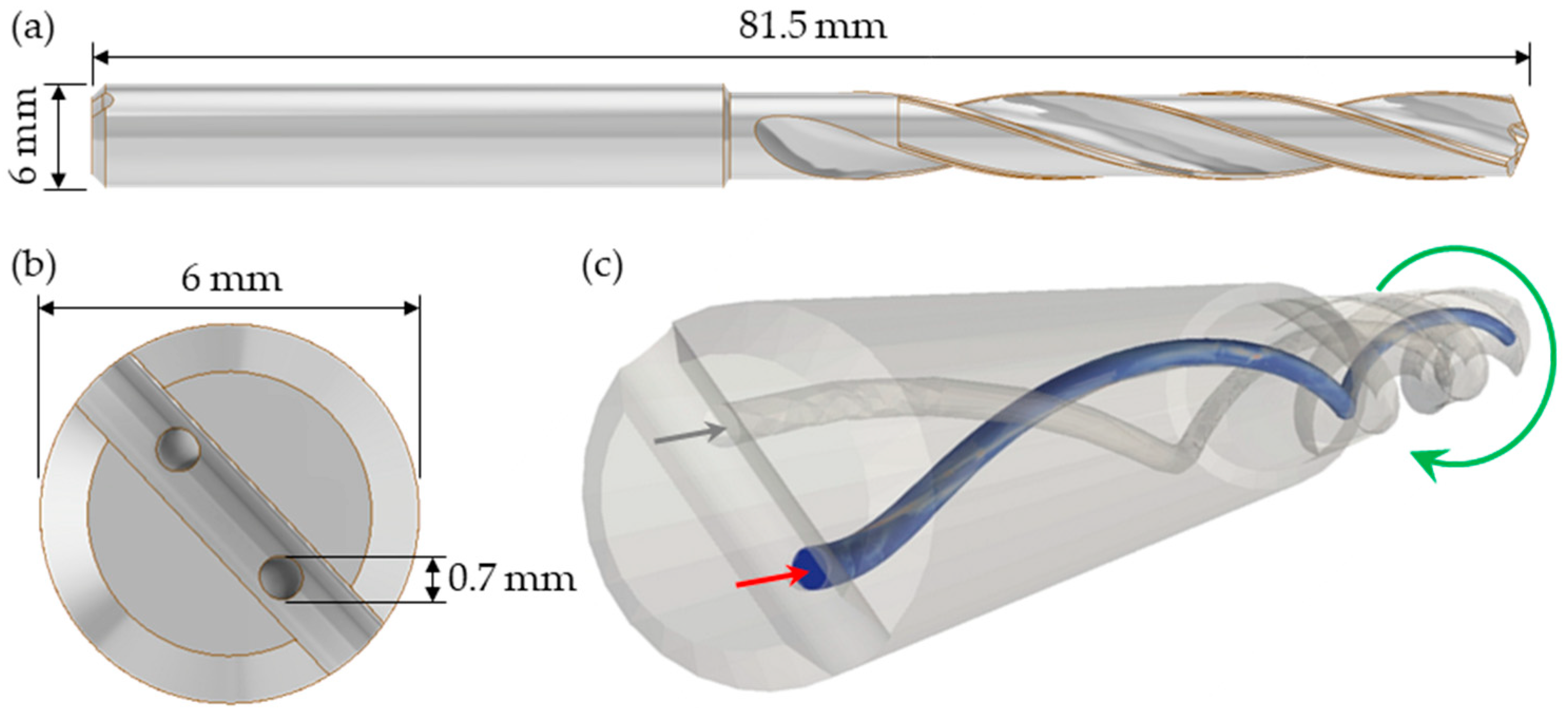
The present study analyzes the internal flow in the MQL feed channel of a twist drill bit, as shown in
Figure 1. The geometry considered consists of one of the two circular internal channels of a twist drill bit. The drill bit under investigation is 6 mm in diameter and ~81.5 mm in length. The length of the channel is just slightly above 80 mm and its diameter is 0.7 mm. The helix angle is about 11.5°. The corresponding computational mesh is shown in
Figure 2, and the domain boundaries are three: inlet, outlet, and channel wall. An O-grid type was employed to discretize the fluid domain with an overall number of hexahedral elements of approximately 3 million. Appropriate refinement of the cells close to the channel wall was adopted with a height of the first layer of about 2 µm. Besides an adequate discretization of the channel cross-section in order to compute the air boundary layer accurately, the numerical solution of the film equations requires a fine discretization of the channel wall to correctly capture the oil film dynamics. The channel wall was represented by approximately 170,000 quadrilateral faces with a resolution of about 30 μm in the axial and azimuthal directions.
Regarding the settings for the solution of the air flow, an inlet mass flow rate of 4.65 × 10⁻⁴ kg/s was fixed, resulting in an average inlet velocity of approximately 126 m/s. Atmospheric pressure was set at the outlet section. The no-slip condition was enforced at the channel wall. Physical properties of air at room temperature were used.
The turbulence modeling requires a value for the inlet turbulent intensity and length scale. The former was chosen equal to 5%, whereas the latter was derived from the standard relation for pipes, which prescribes an inlet turbulent length scale equal to 7% of the pipe diameter, yielding a value of 4.9 × 10⁻⁵ m for the present case.
For the oil droplets, an inlet velocity of 63 m/s, i.e., half of the average air inflow velocity, was considered. Oil droplet diameter and mass flow rate will be discussed later in this section since they are two parameters that varied in the present study. Drag, pressure gradient, and virtual mass forces were considered to determine the overall force exerted on a single particle by the air flow. No parcel approach was employed, i.e., every single oil droplet/particle was tracked. The relevant oil physical properties are summarized in
Table 1.
A time step of 1 × 10⁻⁵ s was adopted for time integration of oil droplet evolution equations.
Droplet splashing and stripping sub-models were enabled for the wall film setup. An alternative to the standard stripping criterion based on critical shear stress, the more general and physical one, based on the dimensionless Weber number, was activated. The threshold value for the Weber number for sub-millimeter films is indicated in [
32]. Integration of the film equations was carried out using a time step of 1 × 10
−6 s, resulting in a ratio of 0.1 concerning the particle time step. The latter was fixed to a higher value in order to reduce the computational cost but still preserving the tracking accuracy.
The last quantities to be mentioned in this section are the parameters to be varied in the present study. The first two parameters are the inlet oil droplet diameter and mass flow rate. The droplet diameter in MQL depends on the liquid properties, process parameters, and operating conditions. A wide range of mist/spray droplet size distributions (DSD) applied to MQL is found in the literature, ranging from DSDs with mean diameters smaller than 10 µm [
38,
39,
40] to DSDs with mean diameters larger than 100 µm [
40,
41,
42]. To investigate the behavior, especially of smaller droplets inside the microchannel with high injection velocities (gas and droplet phases), a uniform distribution was employed with diameters of 2 and 5 µm, respectively. To evaluate the droplet behavior inside the flow, the analysis of the dimensionless Stokes number (St) was performed. The Stokes number is the ratio of the droplet momentum response time to the flow-field time scale [
43]:
where
and
represent the oil density and droplet/particle diameter,
and
are the air dynamic viscosity and inlet velocity, and
denotes the channel diameter.
For St ≪ 1, the droplets will mostly follow the gas motion, while, if St ~ 1, the droplets centrifuge out of the turbulent eddies cores and concentrate on the turbulent eddy peripheries; for St ≫ 1, the carrier gas has minimal influence on the droplet motion [
43,
44]. In this study, the corresponding Stokes number St ranges from approximately 2 to 12. Therefore, a detachment of the particle trajectories from the air flow has to be expected. Four different values were considered regarding the oil droplet volume flow rate Q: 5, 10, 15, and 20 mL/h. The drill bit rotational speed Ω is the third parameter and is assumed to be equal to 0 and 1000 rpm, respectively.
Table 2 presents a resume of operating parameters and conditions applied in the numerical setup.
To ensure the accuracy of the adopted mesh resolution, a grid independence analysis was carried out using the grid convergence index (GCI) method presented by Celik et al. [
45] as a recommended procedure for reporting the uncertainty due to numerical discretization. Three different structured mesh schemes were analyzed with refinement ratios of 1.305 and 1.335 between the meshes. A representative cell size,
h, was computed for each mesh by dividing the entire fluid domain volume by the corresponding number of cells. The grid convergence analysis was performed for the case with an oil droplet volumetric flow rate of 15 mL/h and a droplet diameter of 2 µm. For the GCI analysis, a zero drill bit rotational speed was assumed. The maximum film thickness along the channel wall was monitored for this study. The main parameters calculated with the GCI procedure are presented in
Table 3.
According to
Table 3, the numerical uncertainty with the refined grid resolution is less than 0.1 % (extrapolated relative error). The maximum film thickness presented values of 82.29, 79.65, and 79.31 µm for the coarse, intermediate, and fine meshes, respectively. The extrapolated value of maximum film thickness is 79.25 µm (when
h→0), leading to a GCI of 0.103 %.
To ensure the grid refinement is sufficient, the solution must be in an asymptotic range, i.e., the analyzed variable (in this case, the maximum film thickness) should converge to a single value with the grid refinement.
Figure 3 shows the plot of this quantity as a function of the representative cell size of each mesh. As visible in
Figure 3 (and presented in
Table 3), the maximum film thickness with the finest mesh (79.31 µm) is very close to the value of the extrapolated maximum film thickness (79.25 µm). Therefore, the corresponding grid resolution is adequate for the simulations.
5. Results and Discussion
The present section describes the simulation results of the parametric study. From a qualitative point of view, similar flow conditions were found in all of the different simulations. The initially dispersed oil droplets impinge onto the wall, and a continuous oil wall film develops along the channel wall. The film covers only a limited portion of the wall surface. Almost no oil droplets are found at the outlet section, and the oil flows out of the domain practically only as a film.
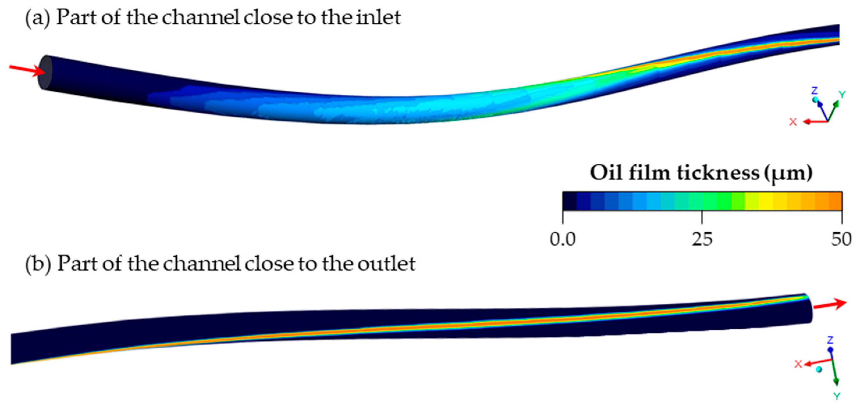
Figure 4 shows the oil film distribution and thickness as a color plot along the channel from two different views. The color plot was obtained from the computation with zero drill bit rotation and oil droplet diameter and flow rate at the inlet section of 2 μm and 5 mL/h, respectively. As mentioned above, the parameters do not, however, affect the qualitative behavior of the flow, which remains unchanged regardless of the specific values of the parameters.
On the other hand, from a quantitative point of view, the different parameters have an influence on the MQL flow.
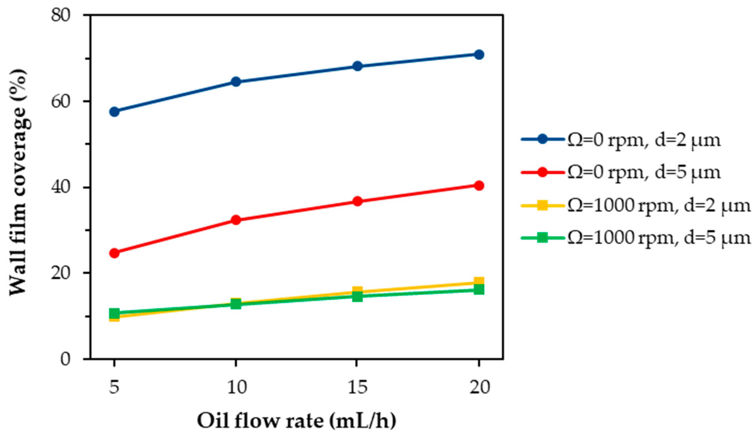
Figure 5 shows the film coverage of the channel wall as a function of the oil inlet flow rate. This quantity measures the percentage of the channel surface that is wetted by the oil film. Each curve in
Figure 5 represents the profile of the film coverage at one of the four possible combinations of the values of the other two parameters, namely the drill bit rotational speed and the oil droplet diameter. The most significant insight provided by this plot is that the film coverage is significantly lower in the case of the rotating drill bit. During the axial rotation, the channel wall moves towards the oil droplets injected at the inlet, reducing the impact area between the droplets and the channel surface. On the contrary, a more significant impact area is found in the case of static drill bit since the impact point of the different droplets is determined solely by their inertia and the interaction with the gas phase.
Another aspect emerging from
Figure 5 is that the film coverage significantly decreases with the size of the oil droplet diameter in the case of Ω = 0 rpm. A lower number of droplets are injected at a fixed flow rate if their diameter increases. Furthermore, the trajectory of more massive droplets is less influenced by the air flow. These two aspects contribute to the reduction of the impact area with the channel wall and, in turn, the film coverage. This effect is not visible for the rotating drill bit at Ω = 1000 rpm, since under these circumstances, the influence of the wall motion on the extension of the impact area dominates over any effects related to the size of the oil droplet diameter.
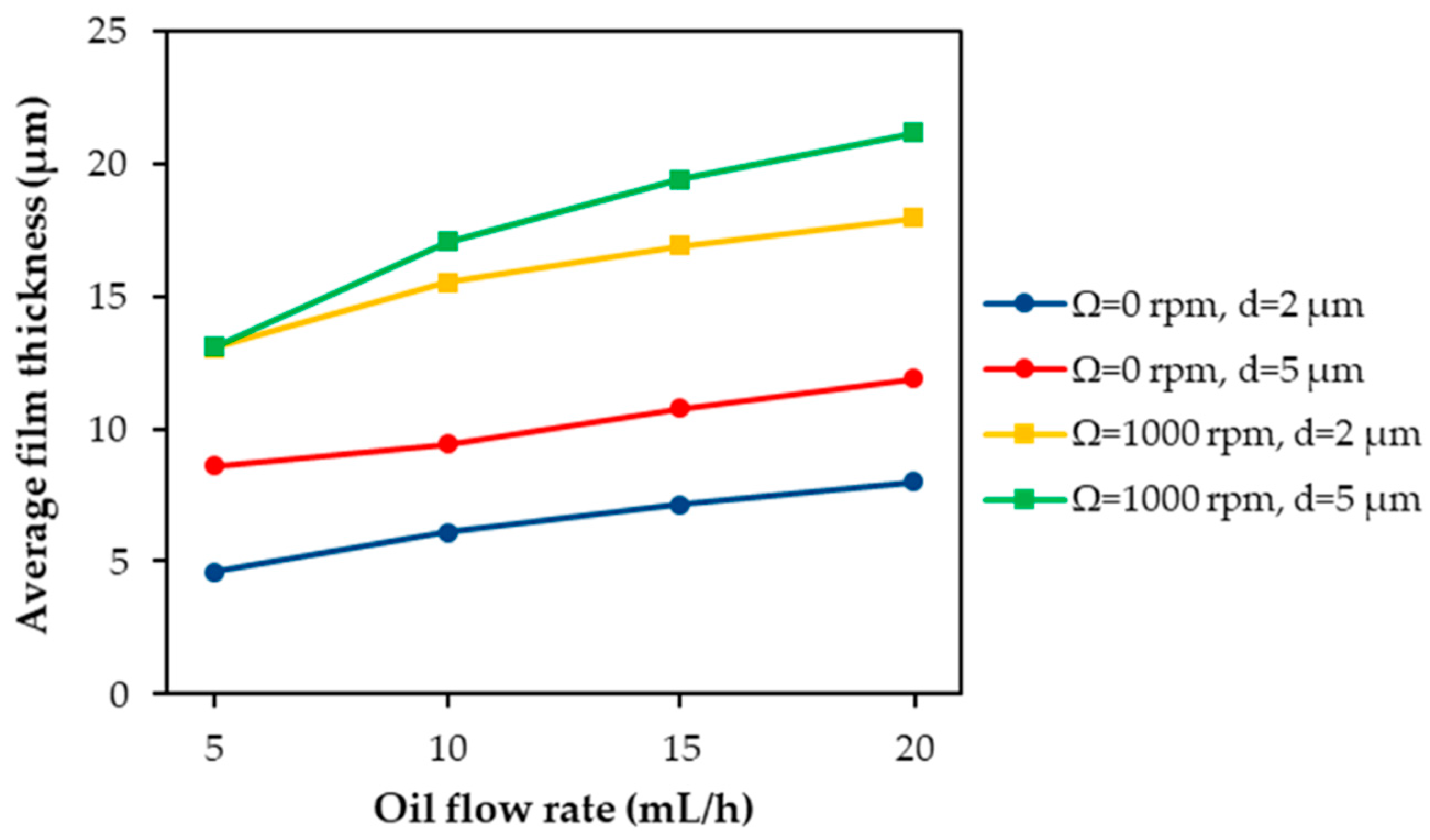
Another quantity obtained from the numerical simulations is the average film thickness of the wetted portion of the channel wall. The influence of the three parameters on this quantity is shown in
Figure 6. This graph is specular to that of
Figure 5. In fact, all of the curves associated with a higher film coverage in
Figure 5 exhibit a lower average film thickness in
Figure 6. The explanation for this fact is straightforward. If the values of the other two parameters lead to a wider film at a fixed oil flow rate, then its thickness must be necessarily lower.
One of the most important results of the simulation is to describe the state of the MQL flow at the end of the channel where the MQL flow exits the drill bit. Therefore, an analysis similar to
Figure 5 is depicted in
Figure 7. In this graph, the focus is on the wetting of the outlet section. Therefore, the quantity on the y-axis of this graph gives the percentage of the outlet circumference covered by the film. This information is crucial since the circumferential spreading of the film at the channel outlet significantly affects the lubrication of the cutting zone.
The first outcome of
Figure 7 is that the values on the y-axis are lower than those of
Figure 5 relative to the film coverage. This occurs because the channel geometry and the interaction with the gas phase constrain the oil film to a narrower portion of the wall surface during its motion along the channel (cf.
Figure 8).
Figure 7 indicates that the effects of the parameters on the exit conditions of the film are less relevant than on the flow configuration further upstream. In detail, the droplet diameter at the channel inlet does not cause any appreciable change of the quantity plotted in
Figure 7. This means that the outlet average film thickness is also virtually independent from this parameter. Therefore, it can be concluded that the oil droplet diameter essentially does not impact, at least concerning the values considered in the present study, the lubrication of the cutting zone, since it cannot determine different flow conditions at the channel outlet. Regarding the drill bit rotational speed, this parameter contributes to increasing the film spreading at the outlet section, mainly at larger oil flow rates.
In addition to the global quantities of the previous plots, some local information on the internal flow conditions in the drill bit channel was also extracted from the simulations.
Figure 9 depicts the profile of the mass transfer rate from the Lagrangian phase to the Eulerian wall film along the channel axial coordinate. The intensity of this mass transfer rate is determined by the local amount of oil droplets trapped by the wall film. At each axial coordinate, this quantity was averaged along the circumference of the channel surface. Each curve in
Figure 9 corresponds to the mass transfer rate profile for a specific combination of the parameter values. All of the curves exhibit high values at smaller axial coordinates, i.e., in the first part of the channel, while the mass transfer becomes practically zero further downstream. In detail, a large peak can be observed close to the entrance in the first quarter of the first helical channel turn. Many droplets hit the wall in this section of the channel, resulting in a film formation from here onwards. After this peak, some more absorption events occur in the remaining part of the first channel turn in the case of d = 2 μm. In the other case of d = 5 μm, the mass transfer sharply drops to zero. In this latter case, the higher Stokes number and, consequently, inertia cause nearly all the droplets to impact the wall very early in the channel, whereas for d = 2 μm, a minor but not a negligible number of droplets travels a greater distance before hitting the channel surface. In general, the Stokes number considerably above 1 does not allow the particle to follow the gas flow well and, therefore, to reach locations further downstream. In fact, after the first part with positive wall impact values, the profiles of
Figure 9 show a mass transfer rate almost equal to 0.
6. Conclusions
In the present work, the MQL flow along the internal channel of a twist drill bit was investigated through numerical simulations. A parametric study was carried out in order to assess the influence of drill bit rotational speed, oil droplet diameter, and oil flow rate on the two-phase flow inside the channel. The Eulerian–Lagrangian–Eulerian model implemented in Ansys Fluent v19.2 was adopted for the flow simulations. This model is specifically able to capture the main features of the interaction of dispersed aerosol flow and liquid wall film formation, where liquid films are developed by impacting droplets along wall surfaces at a reasonable computational cost compared to other modeling approaches.
The simulation results highlight that the main characteristics of MQL flow at the drill bit exit are, qualitatively, just slightly affected by the evaluated process parameters, e.g., the droplet diameter, oil flow rate, and drill rotational speed. A similar oil wall film developed along the channel wall under all of the different conditions considered in the present study. The oil flowed out of the domain, practically only in the form of a liquid film, and almost no droplets could be found at the channel outlet. However, a quantitative inspection showed the influence of the three parameters on different global and local quantities, e.g., film coverage, average film thickness, mass transfer rate. Nonetheless, an analysis restricted to the outlet section has indicated that the oil droplet diameter at the channel inlet has almost no impact on the exit conditions of the MQL flow and, consequently, cannot influence the lubrication of the cutting zone. On the contrary, changes in the value of the drill bit rotation and oil flow rate determine different flow conditions at the channel outlet and, thus, represent significant parameters for MQL of drilling processes.
Future work will be dedicated to simulations of the MQL flow, including the cutting zone in front of the drill bit, to investigate the effects of the specific wetting of the cutting surfaces/edges. Experimental validation of the present simulation results using a shadowgraph optical technique is underway and will also be the subject of future studies.


