Article

A Simple and Effective Modeling Method for 3D Porous Irregular Structures

1
Cyberspace Institute of Advanced Technology, Guangzhou University, Guangzhou 510006, China
2
School of Traffic and Transportation, Shijiazhuang Tiedao University, Shijiazhuang 050043, China
*
Author to whom correspondence should be addressed.
Processes 2022, 10(3), 464; https://doi.org/10.3390/pr10030464
Submission received: 17 January 2022 / Revised: 21 February 2022 / Accepted: 21 February 2022 / Published: 25 February 2022

Abstract

:
Porous structures are kinds of structures with excellent physical properties and mechanical characteristics through components and internal structure. However, the irregular internal morphology of porous structures poses new challenges to product modeling techniques. Traditional computer-aided design (CAD) modeling methods can only represent the external geometric and topological information of models, lacking the description of the internal structure and conformation, which limits the development of new porous products. In this paper, a new simple and effective modeling method for 3D irregular porous structures is proposed, which improves the controllability of pore shape and porosity, thus overcoming the limitations of existing methods in 3D and concave structures. The key idea is to solve isothermal for modeling the porosity of porous units. Experimental results show that the method can easily obtain smooth and approximate porous structures from arbitrary irregular 3D surfaces.

1. Introduction

With the rapid development of aviation, mechatronics, biology, and medical technologies, many fields have put forward requirements for structures with special properties including light weight and strong rigidity, which regular structures cannot satisfy. Mechanical products are evolving from a single structure to products with more complex internal components [1]. Porous objects are structures with special physical properties and mechanical characteristics through components and conformations [2]. Porous structures have stronger scalability in physical and mechanical properties and have solved the problems of light-weighting, explosion-proof, and tribology in engineering [3,4]. By changing the topology of these primitive cells and the proportion of each unit, various composite materials with extreme properties can be designed, such as low thermal expansion coefficient materials with planar fine structure, negative Poisson’s ratio materials, high-performance piezoelectric ceramic materials [5]. However, due to the irregularity and intricacy in cells and internal components, porous structures pose a new challenge to traditional CAD and manufacturing techniques [6].
In recent years, the rapid development of additive manufacturing (AM) has solved the problem of manufacturing products with complex internal components such as porous and porous structures [7,8]. AM (also known as 3D printing) is a technology that uses a gradual accumulation of materials to manufacture solid parts. Compared with traditional subtractive and isotactic manufacturing technologies such as cutting, casting, and stamping, AM does not require tooling fixtures and complex machining processes [9]. It can rapidly produce intricate internal structures, enabling the free manufacturing of parts and solving the manufacturing problem of complex structures like porous structures [10]. More and more artificial porous structures such as truss, honeycomb, and foam structures are prepared with AM [11].
The modeling of porous structures is a challenging task due to the highly irregularity and complexity in geometries [12,13]. The 3D model of a product is the basis for manufacturing [14,15], which determines the structure and performance of the product. Using trial-and-error methods to determine the fine structure is often time-consuming and tedious and does not guarantee an optimal design [16,17]. Although porous structures exist in nature and have been prepared by experimental and reconstructed methods, there are currently no effective CAD methods and tools [18,19].
The modeling methods for products can be divided into two categories: forward modeling and reverse modeling [20]. Reverse modeling is known as a technique of obtaining a 3D digital model of an object through scanning or measuring the physical model. This method can effectively shorten the product design and development cycle and reduce the cost and risk of new product development. However, these advantages are based on the existing physical prototype, which does not facilitate the exploration of new porous structures. The forward modeling, including constructive solid geometry (CSG) and boundary representation (Brep), is a process from scratch, which has more design freedom and is more conducive to exploiting the performance advantages of porous structures. However, existing CAD modeling methods are advantageous in representing simple and regular homogeneous structures and lack effectiveness in modeling porous structural entities with irregular structures or varying material distribution. The lack of porous structure design methods has become an urgent problem in the process of new product development.
To deal with above problems, we propose a novel CAD method called Modeling Complex Porous Objects using the Finite Element Method (MPFEM) for modeling 3D irregular porous structures. MPFEM first tessellates an original surface with 3D centroidal Voronoi diagrams, then generates porous structures with varying components and morphologies by extracting isothermal surfaces of each cell. The main idea behind MPFEM is to convert the design of porous structures into the extraction of isothermal surfaces. Compared with existing methods, our method provides higher design freedom and estimates the stress concentration in irregular 3D porous structures.
The main contributions of this paper are:
(i)
We propose a novel modeling method for irregular 3D porous structures based on the FEM and thermodynamic analysis.
(ii)
We build up 3D porous structures for both intricate convex and concave structures by combining adjacent Voronoi cells.
(iii)
We implementat a prototype system which performs kinds of modeling experiments and shows the effectiveness of the proposed method.
The remainder of this paper is organized as follows: Section 2 briefly reviews background work about modeling methods for porous and heterogeneous objects. Then, Section 3 combines the existing results in the Voronoi tessellation and finite element analysis (FEA) to build up 3D irregular porous structures. Section 4 gives case studies to show the effectiveness of the proposed method. At last, Section 5 concludes the paper and discusses future work.

2. Related Work

The research of CAD and objects modeling has evolved from single and homogeneous productions to composite and heterogeneous objects [6,7,21]. Through the combination of basic parameters, the performance of macroscopic objects consisting of fine structures can be fabricated to meet versatile engineering requirements. These parameters can be the physical properties like stiffness, coefficient of thermal expansion of material particles in fine material cells, or the geometric parameters including distribution of materials, shape, volume fraction [22]. To improve the overall performance of the product, it is necessary to combine the mechanical, physical, and biological advantages of components through the interaction of external form and internal components.
Several theories have been developed for the design and optimization of porous structures. Kim et al. [4] obtained super-strength, low-density, and large-ductility composites by adjusting the dispersion and morphology of the face-center cubic matrix to alleviate the harmful effect on the ductility of the alloy, which is even stronger than the known titanium alloys with the highest strength. Gan et al. [23] developed a new data-driven approach to derive an ideal microstructure and mechanical properties, which combines the thermal-fluid dynamics model, physical-based models, and experimental measurements. Homogenization theory is a common approach in the optimal design of porous structures, which discretizes the structure into periodic pore microstructures. After reviewing the application cases of topological optimization methods based on homogenization theory in metamaterial modeling, Sigmund et al. [5] gave a structural optimization method with periodic fine structure using FEA to model metamaterials, and the optimization criterion method to find the lightest microstructure that satisfies the prescribed properties.
For the design of porous objects, Wang et al. [16] used skin and internal rigid frames to represent the printable 3D model. The exterior of the model is a skin with a certain thickness and the interior is an optimized truss structure. To minimize the volume of truss structures, the authors propose an iterative algorithm by optimizing the rod radius, node position, and the number of truss structures. Lu et al. [24] adopted a honeycomb as the internal structure of the product model to ensure the strength of the model while reducing material loss. The generated 3D porous cells are similar to those obtained with our methods, but it has limitations for modeling concave porous cells. Xu et al. [25] combined the traditional numerical analysis method with model stress distribution and allowable stress information of the material to present a topology optimization algorithm for the force transfer path of the product. To accelerate optimization, the authors introduce a multi-resolution technology from the coarse tetrahedral meshes to fine meshes. Inspired by the random colloid aggregation model, Kou et al. [26] used Voronoi tessellation and cell merging to generate irregular convex and concave pores. However, this design method is mainly aimed at 2D porous structures.
For the fabrication of porous objects, Liu et al. [27] designed a cost-effective method for cellular tissue culture by fused deposition molding, demonstrating the ability of 3D printing technology to rapidly fabricate a variety of different tubular scaffolds. Compton et al. [22] proposed a 3D printing technology to fabricate honeycomb composites in nanoclay sheets doped with epoxy resin filler, which can recover their original shape after external forces are released.

3. A Simple and Effective Modeling Method for 3D Irregular Structures

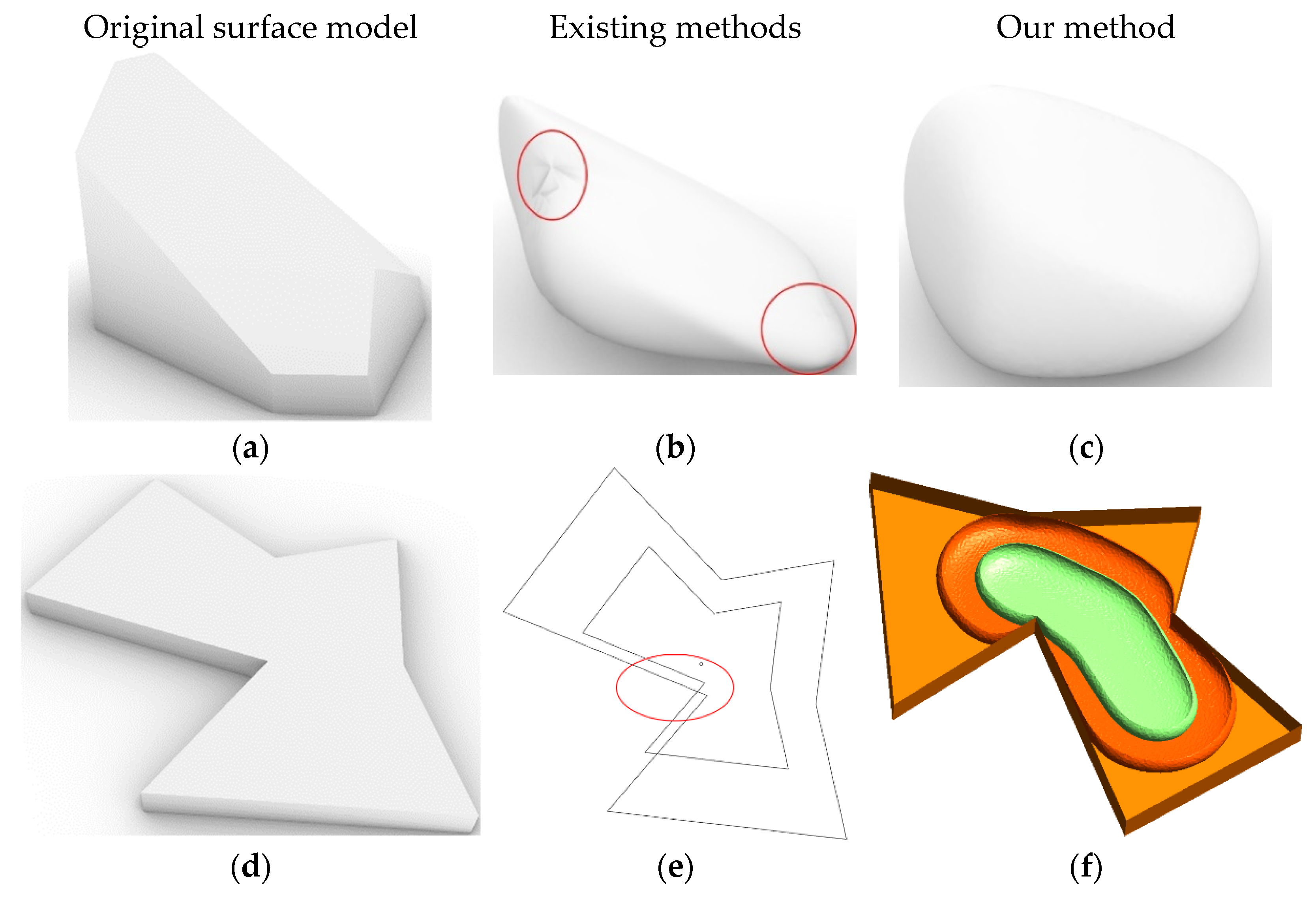
3.1. Problems of Existing Methods

It is a challenging task to establish the rich solid model of a product and give full play to the advantages of physical and mechanical properties [28]. A regular porous structure can be formed by linear or array combination of simple and primitive cells, while it is difficult to model the sizes and distributions of irregular 3D pores. Reverse modeling can only reconstruct the existing model, which is limited by stimuli and constraints and lacks flexibility. Although there are some methods for modeling 3D irregular porous structures, two significant drawbacks remain.
Figure 1 shows the problems of existing modeling methods for 3D porous objects and our improvements. Conventional methods obtain smooth pores from a convex surface including the Catmull-Clark subdivision based on triangular meshes and loop subdivision based on quadrilateral meshes [26,29]. A surface subdivision is a refinement scheme to recursively produce underlying inner mesh from a coarser polygonal mesh. It generates a new set of control vertices including face points, edge points, and vertices from the original control grid, and new points form the new control grid. This iteration will result in a more rounding surface. However, as shown in the red box on the porous structure Figure 1b which is generated from Figure 1a using the recursive subdivision algorithm, the Catmull-Clark subdivision may converge to its limit surface, which can lead to stress concentration. While our method can generate a smoother porous surface as shown in Figure 1c.
To model porous structures, we need to build not only convex but also concave pores. We can obtain concave structures by simply merging convex polyhedrons. It needs to scale the original concave polyhedron to obtain concave pores with different porosities. As shown in Figure 1c, the scaled polyhedron may exceed the boundary of the original model. Therefore, the simple scaling approach is not feasible. While as shown in Figure 1f, the 3D polyhedrons generated by our method not only have a smoother surface but are all inside the original model.
Algorithm 1 shows the flow of our proposed porous structure modeling method. The whole flow consists of three procedures: Voronoi tessellation, concave porous structures generation, and isosurface extraction. In the next sections, we will detail our improvements.
Algorithm 1: Porous Structure Modeling Method.
Processes 10 00464 i001

3.2. Voronoi Tessellation

The core of CAD for porous structures lies in the geometric representation of pore units (meta-structures). To generate porous structure from a single surface model, it needs to tessellate original models. We can find a variety of subdivision schemes for geometric design and graphics applications, where Voronoi tessellation is most widely used [18]. A Voronoi diagram is a tessellation where each polygon (also called Voronoi cell) represents the set of points closest to a central site. In the engineering field, the Voronoi diagram can simulate the foaming process of porous materials to study the various mechanical properties of porous materials. Voronoi diagrams can partition the space into compartments according to the location of the original points (also called sites). Let S = { s i } be a set of distinct sites in a connected compact region Ω . The Voronoi region/cell of Ω i of s i can be defined as:
Ω i = { x Ω | x s i x s j , i j }
If the region is restricted to a finite domain like a square, then all of these divisions are closed regions. However, the Voronoi facets obtained are irregular with a large gap between the shape and area of each facet, and the corresponding triangulation is not good.
To optimize the position of sites for getting a Voronoi facet with more consistent and better triangulation, we use the Centroidal Voronoi Tessellation (CVT) [30] and Lloyd’s relaxation algorithm to make the shape and volume of the dissected polyhedron converge, that is:
s i = c i = Ω i p ( x ) x d σ Ω i p ( x ) d σ
where p ( x )   is a density function greater than 0, and d σ is the area differential on Ω i . This process can be simply understood as updating the sites by recalculating the midpoint of each facepiece, which repeatedly finds the centroid of each set in the partition and then re-partitions the input according to which of these centroids is closest. In this setting, the mean operation is an integral over a region of space, and the nearest centroid operation results. Lloyd relaxation redraws these polygons after moving the seed of each cell to the centroid of that cell. The iteration of this process causes the seeds to space out evenly and settle into a stable state. Finally, each site is moved to the centroid of its Voronoi cell.

3.3. Isosurface Extraction

After obtaining the cells, we need to subdivide the polyhedron to obtain smoother surfaces. As discussed in Section 3.1, Voronoi cells differ from natural objects and suffer from stress concentrations at the vertices and edges of surfaces. If we can get the isothermal surface information inside the Voronoi cell, we can use it as a boundary to get a smoother pore without introducing discontinuities along prescribed boundaries.
To extract the isosurface, we adopt the finite element method (FEM) [31]. FEM is a numerical method for solving partial differential equations (PDEs) based on the mathematical theory of the weak solution of PDEs. To solve a system of a PDE and compute a temperature distribution, we express the resulting weak form for Poisson’s problem to find the unknown function T V ( Ω ) for any test function s such that:
{ Ω c s t = 0 ,     s ( Ω C ) T ( t ) = T h ,   t Ω o u t T ( t ) = T l , t Ω i n
where Ω R n is the solution domain with the boundary Ω = Ω o u t Ω i n . Ω   are also called essential boundary conditions (EBC), Ω i n is the defined cell’s centroids which can be either a single point or a sequence of points. Ω o u t is the surface of the model. s should be zero on domains Ω . c is the material constant which does not influence the solution for our simulation. The boundary conditions place restrictions on the finite element formulation and result in a unique solution to the problem. We specify that a temperature of 100 is applied to the T h and 0 to the T l .
After defining the boundary conditions, we use the available finite element tools to perform meshing and finite element analysis. Finally, in the post-processing process, we extract all the meshes on the specified temperature values and stitch them together to make the boundary of a pore. since the polyhedron we use is closed, the final generated pore is also closed. We perform finer meshing to obtain smoother pores. Meanwhile, due to the smoothness of the isothermal surface, the constructed porous structure model eliminates the stress concentration phenomenon.
We can obtain a more adaptive isosurface by defining a more complex temperature distribution. When solving a Poisson equation of temperature diffusion, the temperature field is linear. If the isothermal surface is extracted directly from the temperature values, the porosity of the generated pore model is not linear. To address this issue, we extract the isothermal surface using the following transformation:
{ i s o t = i s o m i n + ( p v ) 1 / 3 × ( i s o m a x i s o m i n ) i s o m i n = T l + α × ( T h T l ) i s o m a x = T h
where p v is the porosity prescribed by users and i s o t is the corresponding temperature value. Note that the temperature values obtained do not strictly correspond to p v . We can also iterate one by one on the isothermal surface to invert the exact temperature value corresponding to the porosity exactly. However, modeling the exact internal geometric and topological structure of pore objects is often not necessary and this method requires iterations for each pore model, which will increase the computational afford. In contrast, the above equation provides a general approximation to extract isosurface from T l . We truncate the lowest temperature value since the temperature field generated by the FEM solver is concentrated near the centroid sites, which will gradually thin out at the outer boundary because the volume is a cubic function. to remove the small isothermal surface near sites, we require the porosity of porous structures to be greater than 0.5, and we set α = 0.8 . We can also change the truncation threshold according to different requirements.

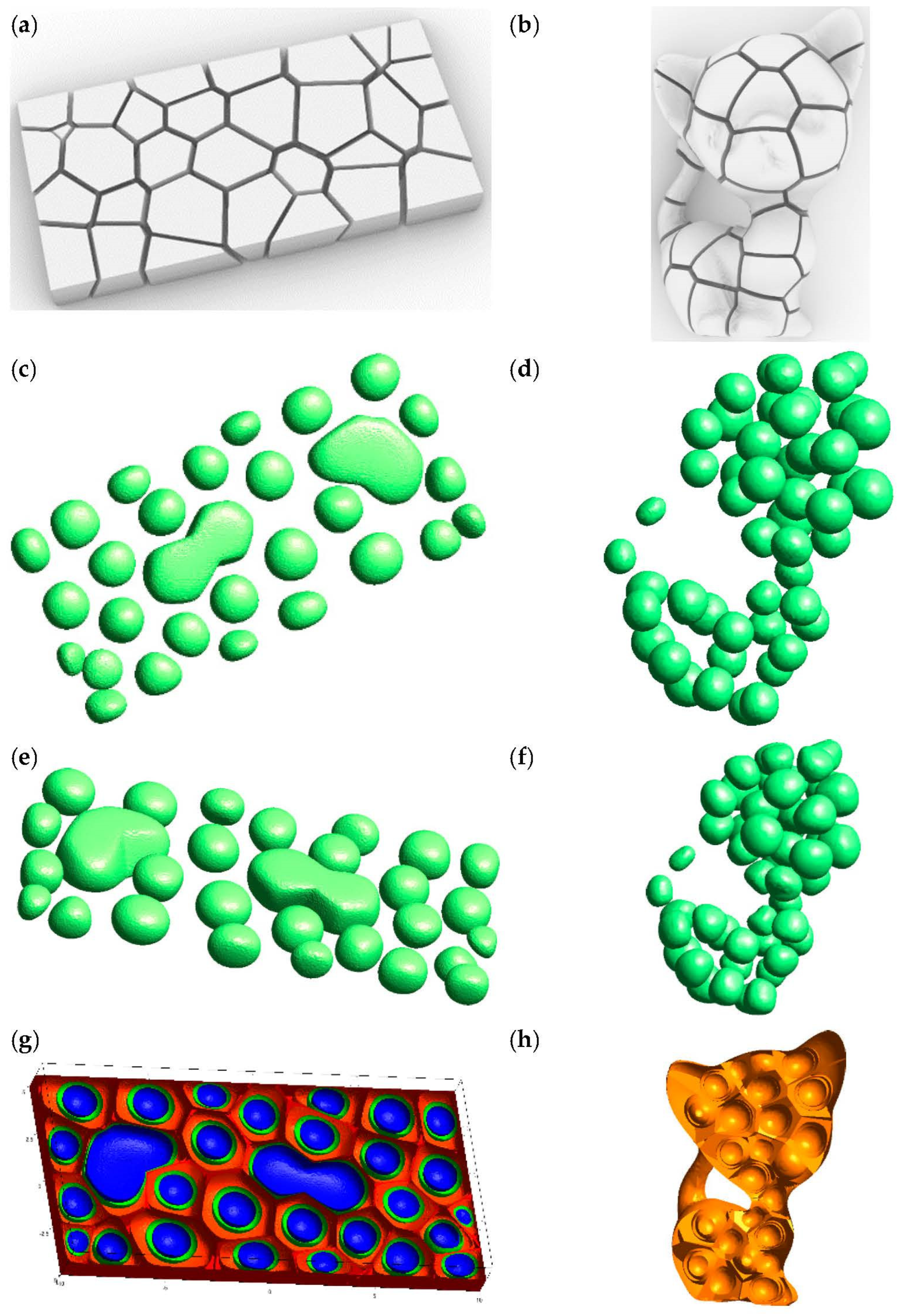
3.4. Concave Porous Structures

Voronoi tessellation can only produce convex polyhedrons [30]. Although concave polyhedrons can be obtained by merging multiple Voronoi cells, we still need to solve the problem of centroids of the merge concave pores. The proposed method allows users to specify the pairing relationship of neighboring Voronoi cells. If two or more adjacent Voronoi cells are specified as a pair, we treat them as one whole-cell and merge the paired convex structures by a Boolean-Union operation. In this case, if T h is simply applied to the merged outer surface and T l is applied to the separate center of the merged concave cell, the generated isothermal surface will be clustered near the center and deviate from the outer original non-adjacent surface because of the concave shape property, which will also create a stress concentration problem. As shown in Figure 2a, if we use the centroids of original cells directly, although the boundary is concave, the distribution of internal isothermal surfaces still obeys the convex cell, which does not meet our requirement of generating concave isothermal surfaces.
When adjusting the porosity, the scaled concave polygon may exceed the original boundary and overlap with other concave pores. It is necessary to adjust the scaled concave polygon boundary to confine it inside the original surface and ensure that each pore does not overlap. To improve the design freedom of pores and better simulate the porous structure, the outsourced polyhedron of the concave pore structure can be obtained by combining multiple neighboring cells. We extract the boundary of each paired Voronoi diagram and remove the duplicated faces to obtain the concave pore contour after Voronoi tessellation. To make the generated isothermal surface fit better with the outer surface, we calculate the center C 0 of the paired adjacent face, and then generate the line segment C 1 C 0 and C 2 C 0 , where C 1 and C 2 are original centroids of paired Voronoi cells, respectively. As shown in Figure 2b, we sample the two-line segments to generate multiple centers C l = t C i C 0 ,   i = { 1 , 2 } . In the finite element analysis stage, we apply T l to the all mesh containing C l . As shown in Figure 2c, the generated isothermal surface is closer to the outsourcing profile. We can generate more realistic pores by simply resampling sites.

4. Modeling Experiments

In this section, we will perform several kinds of modeling experiments to verify the effectiveness of the proposed method. The proposed method benefits from the mature and widely used methods including Voronoi tessellation and FEM, which makes our method easy to implement with existing software and tools. During the solid model construction and Voronoi tessellation, we utilize the Grasshopper [32] tool, which is a graphical algorithm editor plugin for Rhino. For meshing, we use the Gmsh [33] tool. Gmsh is an open-source 3D finite element mesh generator whose fast and lightweight parametric features facilitate high-quality network delineation. We use the Python finite element library sfepy [34] to compute the thermal map. sfepy is a flexible Python finite element analysis toolkit for the rapid implementation and testing of finite element models in research. These tools support secondary development based on Python, so the whole modeling process of porous structures can be automated using the Python language, thus improving modeling efficiency. Note that although thermodynamic diffusion is a time-series problem, we do not need to define a time-stepping solver in sfepy, because the isothermal problem is stationary and the default solver can solve it once.
As shown in Figure 3a, the isosurfaces generated by FEM are consistent with the scaled sphere. It infers the accuracy of the proposed method. The different color surfaces of Figure 3b,c represent the isosurfaces of polyhedrons, where we sample fewer isosurfaces to see the extracted isothermal surface more clearly. Figure 3d shows the isosurfaces from a concave polyhedron. Figure 3e,f are the resulting pore structures with different porosities. By extracting isothermal surfaces at different temperatures such as 99 and 95, we can obtain pore structures with the required porosity. For convex and concave structures, the closer to the center, the more spherical the isosurface tends to be. At the boundary, the isosurface is the fusion of polyhedron and enveloping sphere.
Figure 4 shows the process of generating porous structures from cuboid and more complex kitten models. The blue, light green, and dark yellow colors in Figure 4g represent the corresponding 99.9, 99, and 98 isothermals, respectively. Although the kitten model has a complex surface, the generated pores are still smooth and natural as shown in Figure 4d,f. From the modeling experiments above, we can conclude that we can obtain both smooth and approximate porous structures from any irregular 3D structures with the method proposed in this paper.

5. Conclusions and Future Work

Recently, porous structures have become widely used in the fields of aviation, mechatronics, biology, and mechanics. The ability to design new products relies on the representations of models. However, intricate inner components, which enable excellent physical properties and mechanical characteristics in porous structures, pose new challenges for traditional CAD methods. In this paper, we combine the Voronoi tessellation and FEA methods to propose a novel modeling method called MPFEM to generate irregular and smooth 3D pores from polyhedrons. Different from previous modeling methods aimed at 2D geometric representation of convex structures, our method can process both 3D and complex concave structures. MPFEM can generate convave porous structures which are combined adjacent Voronoi cells and smooth surfaces which estimate a stress concentration. A series of convex, concave, and complex polyhedron modeling experiments show that this proposed method is easy and feasible, and the results show good performance in terms of smoothness and fitness of geometric representation.
As future work, first, although the purpose of this paper is modeling solids of porous structures, we can extend it to other fields such as the current popular functionally graded material (FGM). Since the generated isothermal surfaces are smoother, the problem of mismatching material interface properties can be further eliminated. By distributing different materials on different isothermal surfaces, the proposed method can also provide a new idea for the modeling of FGM. Second, through an evolutionary or neural network (NN) [35] algorithms to obtain the distribution, combination, and porosity of porous structures under specific load and boundary constraints, we can realize function designs like the lightweight. Since the optimization goal becomes site locations and porosities, which eliminates model meshing in traditional FEA, our method will significantly improve design efficiency. Last but not least, we will utilize the AM including direct light processing (DLP) to fabricate generating 3D porous models.

Author Contributions

Conceptualization, investigation, methodology, and writing: D.Z.; validation and data curation: L.R. All authors have read and agreed to the published version of the manuscript.

Funding

This work is supported in part by the National Key Research and Development Program of China (2019YFB1706003), and the Natural Science Foundation of Guangdong Province, China (grant number 2214050004382).

Institutional Review Board Statement

Not applicable.

Informed Consent Statement

Not applicable.

Data Availability Statement

The data presented in this study are available on request from the corresponding author.

Conflicts of Interest

The authors declare that they have no known competing financial interests or personal relationships that could have appeared to influence the work reported in this paper.

References

  1. Gao, Z.; Nguang, S.K.; Kong, D.-X. Advances in Modelling, Monitoring, and Control for Complex Industrial Systems. Complexity 2019, 2019, 2975083. [Google Scholar] [CrossRef]
  2. Liu, W. Progress in additive manufacturing on complex structures and high-performance materials. J. Mech. Eng. 2019, 55, 128–151. [Google Scholar] [CrossRef]
  3. Zhang, D.; Zhao, Z.; Zhou, Y.; Guo, Y. A novel complex network-based modeling method for heterogeneous product design. Clust. Comput. 2019, 22, 7861–7872. [Google Scholar] [CrossRef]
  4. Kim, S.-H.; Nack, J.; Hansoo, K. Brittle intermetallic compound makes ultrastrong low-density steel with large ductility. Nature 2015, 518, 77–79. [Google Scholar] [CrossRef]
  5. Sigmund, O. Systematic design of metamaterials by topology optimization. In Proceedings of the IUTAM Symposium on Modelling Nanomaterials and Nanosystems, Aalborg, Denmark, 19–22 May 2009. [Google Scholar] [CrossRef]
  6. Gupta, V. CAD modeling and rapid manufacturing of heterogeneous objects: A review. Int. J. Tech. Res. Appl. 2014, 3, 30–35. [Google Scholar]
  7. Li, B.; Fu, J.; Feng, J.; Shang, C.; Lin, Z. Review of heterogeneous material objects modeling in additive manufacturing. Vis. Comput. Ind. Biomed. 2020, 3, 1–18. [Google Scholar] [CrossRef]
  8. Dichen, L.I. Additive Manufacturing: Integrated Fabrication of Macro/Microstructures. J. Mech. Eng. 2013, 49, 129. [Google Scholar] [CrossRef]
  9. Denghui, Z.; Guo, Y.; Zhao, Z.; Zhou, Y. Co-authorship Networks in Additive Manufacturing Studies Based on Social Network Analysis. Br. J. Appl. Sci. Technol. 2016, 15, 1–6. [Google Scholar] [CrossRef]
  10. Haleem, A.; Javaid, M. Additive Manufacturing Applications in Industry 4.0: A Review. J. Ind. Integr. Manag. 2019, 4, 1930001. [Google Scholar] [CrossRef]
  11. Nagarajan, B.; Hu, Z.; Song, X.; Zhai, W.; Wei, J. Development of Micro Selective Laser Melting: The State of the Art and Future Perspectives. Engineering 2019, 5, 702–720. [Google Scholar] [CrossRef]
  12. Gao, L.; Shen, W.; Li, X. New Trends in Intelligent Manufacturing. Engineering 2019, 5, 619–620. [Google Scholar] [CrossRef]
  13. Gao, Z.; Kong, D.; Gao, C. Modeling and Control of Complex Dynamic Systems: Applied Mathematical Aspects. J. Appl. Math. 2012, 2012, 869792. [Google Scholar] [CrossRef] [Green Version]
  14. Rosen, D.W. Thoughts on Design for Intelligent Manufacturing. Engineering 2019, 5, 609–614. [Google Scholar] [CrossRef]
  15. Wang, L. From Intelligence Science to Intelligent Manufacturing. Engineering 2019, 5, 615–618. [Google Scholar] [CrossRef]
  16. Wang, W.; Wang, T.Y.; Yang, Z.; Liu, L.; Tong, X.; Tong, W.; Deng, J.; Chen, F.; Liu, X. Cost-effective printing of 3D objects with skin-frame structures. ACM Trans. Graph. (TOG) 2013, 32, 1–10. [Google Scholar] [CrossRef] [Green Version]
  17. Koeppe, A.; Padilla, C.A.H.; Voshage, M.; Schleifenbaum, J.H.; Markert, B. Efficient numerical modeling of 3D-printed lattice-cell structures using neural networks. Manuf. Lett. 2018, 15, 147–150. [Google Scholar] [CrossRef]
  18. Martínez, J.; Dumas, J.; Lefebvre, S. Procedural voronoi foams for additive manufacturing. ACM Trans. Graph. 2016, 35, 1–12. [Google Scholar] [CrossRef] [Green Version]
  19. Liu, L.G.; Xu, W.P.; Wang, W.M.; Yang, Z.W.; Liu, X.P. Survey on geometric computing in 3D printing. Chin. J. Comput. 2015, 38, 1243–1267. [Google Scholar] [CrossRef]
  20. Andrews, J.; Jin, H.; Sequin, C. Interactive Inverse 3D Modeling. Comput.-Aided Des. Appl. 2013, 9, 881–900. [Google Scholar] [CrossRef]
  21. Kou, X.Y.; Tan, S.T. Heterogeneous object modeling: A review. Comput. Aided Des. 2007, 39, 284–301. [Google Scholar] [CrossRef]
  22. Compton, B.G.; Lewis, J.A. 3D-printing of lightweight cellular composites. Adv. Mater. 2014, 26, 5930–5935. [Google Scholar] [CrossRef] [PubMed]
  23. Gan, Z.; Li, H.; Wolff, S.J.; Bennett, J.L.; Hyatt, G.; Wagner, G.J.; Cao, J.; Liu, W.K. Data-Driven Microstructure and Microhardness Design in Additive Manufacturing Using a Self-Organizing Map. Engineering 2019, 5, 730–735. [Google Scholar] [CrossRef]
  24. Lu, H.Z.L.; Wei, A.S.Y.; Fan, Q.; Chen, X.; Savoye, Y.; Tu, C.; Cohen-Or, D.; Chen, B. Build-to-last: Strength to weight 3D printed objects. ACM Trans. Graph. (Proc. SIGGRAPH) 2014, 33, 1–10. [Google Scholar] [CrossRef]
  25. Xu, W.; Wang, W.; Li, H.; Yang, Z.; Liu, L. Topology Optimization for Minimal Volume in 3D Printing. J. Comput. Res. Dev. 2015, 52, 38. [Google Scholar] [CrossRef]
  26. Kou, X.Y.; Tan, S.T. A simple and effective geometric representation for irregular porous structure modeling. Comput.-Aided Des. 2010, 42, 930–941. [Google Scholar] [CrossRef] [Green Version]
  27. Liu, K.; Jiang, L. Bio-inspired design of multiscale structures for function integration. Nano Today 2011, 6, 155–175. [Google Scholar] [CrossRef]
  28. Zhang, D.; Zhou, Y.; Guo, Y. A modeling and optimization method for heterogeneous objects based on complex networks theory. Clust. Comput. 2019, 22, 2645–2654. [Google Scholar] [CrossRef]
  29. Ma, W. Subdivision surfaces for CAD—An overview. Comput.-Aided Des. 2005, 37, 693–709. [Google Scholar] [CrossRef]
  30. Wang, X.; Ying, X.; Liu, Y.-J.; Xin, S.-Q.; Wang, W.; Gu, X.; Mueller-Wittig, W.; He, Y. Intrinsic computation of centroidal Voronoi tessellation (CVT) on meshes. Comput.-Aided Des. 2015, 58, 51–61. [Google Scholar] [CrossRef]
  31. Tornabene, F.; Fantuzzi, N.; Ubertini, F.; Viola, E. Strong formulation finite element method based on differential quadrature: A survey. Appl. Mech. Rev. 2015, 67, 020801. [Google Scholar] [CrossRef]
  32. Roudsari, M.S.; Pak, M.; Smith, A. Ladybug: A parametric environmental plugin for grasshopper to help designers create an environmentally-conscious design. In Proceedings of the 13th International IBPSA Conference, Lyon, France, 26–28 August 2013; pp. 3128–3135. [Google Scholar]
  33. Geuzaine, C.; Remacle, J.-F. Gmsh: A 3-D finite element mesh generator with built-in pre- and post-processing facilities. Int. J. Numer. Methods Eng. 2009, 79, 1309–1331. [Google Scholar] [CrossRef]
  34. Cimrman, R.; Lukeš, V.; Rohan, E. Multiscale finite element calculations in Python using SfePy. Adv. Comput. Math. 2019, 45, 1897–1921. [Google Scholar] [CrossRef] [Green Version]
  35. Villarrubia, G.; de Paz, J.F.; Chamoso, P.; la Prieta, F.D. Artificial neural networks used in optimization problems. Neurocomputing 2018, 272, 10–16. [Google Scholar] [CrossRef]
Figure 1. Problems of current 3D porous structure modeling methods and our improvements. (a) is a 3D surface model; (b) is the generated pore with the subdivision surface algorithm from the convex model (a) which leads to stress concentration phenomena; (c) is the generated pore from (a) with our proposed method; (d) is an extrusion surface model; (e) is the cross-scaling surface from the concave model (d); (f) is generated isothermal surfaces from (d) with our method. The different colors in (f) represent different isothermal surfaces, and the same color means that the geometric units in them have the same temperature.
Processes 10 00464 g001
Figure 2. The construction of constraints for concave polyhedron. (a) is the concave surface and separate isothermal surfaces; (b) is generated centroids of a concave polyhedron from origin centroids and the common face; (c) is extracted isothermal surfaces using the EBC from (b).
Processes 10 00464 g002
Figure 3. Isosurfaces generated by convex polyhedrons. (a) sphere; (b) polyhedron; (c) section polyhedron; (d) concave polyhedron; (e) is a pore generated from the 99 isothermal surfaces. (f) is a pore generated from the 95 isothermal surfaces. The different color represents different isosurfaces (isothermals).
Processes 10 00464 g003
Figure 4. Porous structures generated from cuboid and kitten surfaces. (a) is a tessellated cuboid Voronoi cells; (b) a tessellated cat Voronoi cells; (c) is generated pores from (a) with 98 isothermals; (d) is generated pores from (b) with 98 isothermals; (e) is generated pores from (a) with 99 isothermals; (f) is generated pores from (b) with 99 isothermals; (g) are resulting porous structures for (a); (h) are resulting porous structures for (b).
Processes 10 00464 g004
Publisher’s Note: MDPI stays neutral with regard to jurisdictional claims in published maps and institutional affiliations.

